EP0244524B1 - Methode zur Herstellung von dekorativen Emblemen und dergleichen sowie auf diese Weise hergestellte Gegenstände - Google Patents
Methode zur Herstellung von dekorativen Emblemen und dergleichen sowie auf diese Weise hergestellte Gegenstände Download PDFInfo
- Publication number
- EP0244524B1 EP0244524B1 EP19860303510 EP86303510A EP0244524B1 EP 0244524 B1 EP0244524 B1 EP 0244524B1 EP 19860303510 EP19860303510 EP 19860303510 EP 86303510 A EP86303510 A EP 86303510A EP 0244524 B1 EP0244524 B1 EP 0244524B1
- Authority
- EP
- European Patent Office
- Prior art keywords
- substrate
- punch
- die
- shape
- cutting
- Prior art date
- Legal status (The legal status is an assumption and is not a legal conclusion. Google has not performed a legal analysis and makes no representation as to the accuracy of the status listed.)
- Expired
Links
- 238000000034 method Methods 0.000 title claims description 23
- 239000000758 substrate Substances 0.000 claims description 115
- 238000005520 cutting process Methods 0.000 claims description 61
- 229920003023 plastic Polymers 0.000 claims description 27
- 239000004033 plastic Substances 0.000 claims description 27
- 239000011248 coating agent Substances 0.000 claims description 11
- 238000000576 coating method Methods 0.000 claims description 11
- 239000000853 adhesive Substances 0.000 claims description 9
- 230000001070 adhesive effect Effects 0.000 claims description 9
- 229910000831 Steel Inorganic materials 0.000 claims description 4
- 239000010959 steel Substances 0.000 claims description 4
- 230000000994 depressogenic effect Effects 0.000 claims description 3
- 238000003825 pressing Methods 0.000 claims description 3
- 230000000694 effects Effects 0.000 claims description 2
- 238000004519 manufacturing process Methods 0.000 claims description 2
- 238000007723 die pressing method Methods 0.000 claims 2
- 238000006073 displacement reaction Methods 0.000 claims 1
- 239000011888 foil Substances 0.000 description 14
- 230000000712 assembly Effects 0.000 description 11
- 238000000429 assembly Methods 0.000 description 11
- 239000010410 layer Substances 0.000 description 10
- 229920002635 polyurethane Polymers 0.000 description 9
- 239000004814 polyurethane Substances 0.000 description 9
- 239000000203 mixture Substances 0.000 description 6
- 229920005862 polyol Polymers 0.000 description 5
- 150000003077 polyols Chemical class 0.000 description 5
- 230000032798 delamination Effects 0.000 description 4
- 230000002093 peripheral effect Effects 0.000 description 4
- 239000004721 Polyphenylene oxide Substances 0.000 description 3
- 229910052782 aluminium Inorganic materials 0.000 description 3
- XAGFODPZIPBFFR-UHFFFAOYSA-N aluminium Chemical compound [Al] XAGFODPZIPBFFR-UHFFFAOYSA-N 0.000 description 3
- 239000003054 catalyst Substances 0.000 description 3
- 238000010276 construction Methods 0.000 description 3
- 238000010438 heat treatment Methods 0.000 description 3
- 239000007788 liquid Substances 0.000 description 3
- 229910052751 metal Inorganic materials 0.000 description 3
- 239000002184 metal Substances 0.000 description 3
- 239000006223 plastic coating Substances 0.000 description 3
- 229920005906 polyester polyol Polymers 0.000 description 3
- 229920000570 polyether Polymers 0.000 description 3
- 238000004080 punching Methods 0.000 description 3
- 238000007906 compression Methods 0.000 description 2
- 230000006835 compression Effects 0.000 description 2
- 125000005442 diisocyanate group Chemical group 0.000 description 2
- 210000005069 ears Anatomy 0.000 description 2
- 239000000463 material Substances 0.000 description 2
- 230000005855 radiation Effects 0.000 description 2
- 229920002176 Pluracol® Polymers 0.000 description 1
- 239000004698 Polyethylene Substances 0.000 description 1
- BLRPTPMANUNPDV-UHFFFAOYSA-N Silane Chemical compound [SiH4] BLRPTPMANUNPDV-UHFFFAOYSA-N 0.000 description 1
- 239000012790 adhesive layer Substances 0.000 description 1
- 239000004411 aluminium Substances 0.000 description 1
- 239000005030 aluminium foil Substances 0.000 description 1
- 239000002131 composite material Substances 0.000 description 1
- 150000001875 compounds Chemical class 0.000 description 1
- 238000001816 cooling Methods 0.000 description 1
- 230000008021 deposition Effects 0.000 description 1
- 230000000881 depressing effect Effects 0.000 description 1
- KORSJDCBLAPZEQ-UHFFFAOYSA-N dicyclohexylmethane-4,4'-diisocyanate Chemical group C1CC(N=C=O)CCC1CC1CCC(N=C=O)CC1 KORSJDCBLAPZEQ-UHFFFAOYSA-N 0.000 description 1
- 239000000428 dust Substances 0.000 description 1
- 229920001971 elastomer Polymers 0.000 description 1
- 238000004049 embossing Methods 0.000 description 1
- 229920002457 flexible plastic Polymers 0.000 description 1
- 238000009472 formulation Methods 0.000 description 1
- 239000012948 isocyanate Substances 0.000 description 1
- 150000002513 isocyanates Chemical class 0.000 description 1
- QSHDDOUJBYECFT-UHFFFAOYSA-N mercury Chemical compound [Hg] QSHDDOUJBYECFT-UHFFFAOYSA-N 0.000 description 1
- 229910052753 mercury Inorganic materials 0.000 description 1
- 230000035515 penetration Effects 0.000 description 1
- -1 polyethylene Polymers 0.000 description 1
- 229920000573 polyethylene Polymers 0.000 description 1
- 229920001451 polypropylene glycol Polymers 0.000 description 1
- 230000001681 protective effect Effects 0.000 description 1
- 238000006748 scratching Methods 0.000 description 1
- 230000002393 scratching effect Effects 0.000 description 1
- 229910000077 silane Inorganic materials 0.000 description 1
Images

Classifications
-
- B—PERFORMING OPERATIONS; TRANSPORTING
- B44—DECORATIVE ARTS
- B44C—PRODUCING DECORATIVE EFFECTS; MOSAICS; TARSIA WORK; PAPERHANGING
- B44C3/00—Processes, not specifically provided for elsewhere, for producing ornamental structures
- B44C3/02—Superimposing layers
-
- B—PERFORMING OPERATIONS; TRANSPORTING
- B44—DECORATIVE ARTS
- B44C—PRODUCING DECORATIVE EFFECTS; MOSAICS; TARSIA WORK; PAPERHANGING
- B44C1/00—Processes, not specifically provided for elsewhere, for producing decorative surface effects
- B44C1/10—Applying flat materials, e.g. leaflets, pieces of fabrics
- B44C1/105—Applying flat materials, e.g. leaflets, pieces of fabrics comprising an adhesive layer
-
- B—PERFORMING OPERATIONS; TRANSPORTING
- B44—DECORATIVE ARTS
- B44C—PRODUCING DECORATIVE EFFECTS; MOSAICS; TARSIA WORK; PAPERHANGING
- B44C1/00—Processes, not specifically provided for elsewhere, for producing decorative surface effects
- B44C1/20—Applying plastic materials and superficially modelling the surface of these materials
-
- B—PERFORMING OPERATIONS; TRANSPORTING
- B44—DECORATIVE ARTS
- B44C—PRODUCING DECORATIVE EFFECTS; MOSAICS; TARSIA WORK; PAPERHANGING
- B44C3/00—Processes, not specifically provided for elsewhere, for producing ornamental structures
- B44C3/08—Stamping or bending
- B44C3/082—Stamping or bending comprising a cutting out operation
-
- B—PERFORMING OPERATIONS; TRANSPORTING
- B44—DECORATIVE ARTS
- B44C—PRODUCING DECORATIVE EFFECTS; MOSAICS; TARSIA WORK; PAPERHANGING
- B44C5/00—Processes for producing special ornamental bodies
- B44C5/04—Ornamental plaques, e.g. decorative panels, decorative veneers
Definitions
- the present invention relates to a method for making decorative emblems, plaques, and the like (hereafter generically called "decorative shapes") which have a cured plastic layer over a decorative surface. More particularly it relates to a method in which a plurality of individual coated shapes are stamped from a single substrate without damaging the plastic coat or deforming the shape during the die cutting operation.
- this dome is of aesthetic value, the depth of the dome is difficult to control and the domed shape is difficult to apply to a flat surface or a surface where the radius of curvature is substantially different than that of the dome.
- a dome is imparted to the shape as it is die cut, it is difficult to obtain decorative shapes having a sharply cut vertical edge, occasionally the shape may delaminate, scratch or chip, and there is some edge deformation and slivering of the foil substrate.
- the adhesive There is also a tendency for the adhesive to ooze from the substrate and contaminate the mold when it is die cut. All of these drawbacks contribute to a reduction in the weather resistance of the cut shape.
- a typical decorative shape produced in accordance with the present invention and the aforementioned U. S. Patent is stamped from a laminate including a sheet of aluminum painted or silk-screened on one side with a decorative insignia or graphic which is over coated with a layer of cured polyurethane and coated on the other side with an adhesive composition.
- the adhesive layer is overlayed with a sheet of release paper.
- FIG. 1 One example of this laminate is shown in the accompanying Fig. 1.
- FR-A-2507949 discloses an apparatus which is similar in some respects to the apparatus used in carrying out the present invention.
- individual decorative shapes are die cut from a substrate comprising a plastics sheet, or a varnished metal sheet, on which a series of decorative designs are reproduced.
- a cutting die set is used in which a pressure platform is resiliently mounted in a female cutting die. The substrate is said to be supported flat against the pressure platform, the area of the decorative shape under the punch being sandwiched between the platform and the punch.
- the cutting die set closes on the substrate and the pressure platform biases the substrate against the male punch.
- the male punch forces the substrate into the cutting die by depressing the pressure platform, to cut out the shape from the substrate.
- the press opens, and the platform, under its resilient mounting, returns to its pre-cutting position. In so doing, the shape cut from the substrate is pressed back into the opening in the substrate selvage from which it has been cut, for carriage to a station where the shape is ejected from the substrate and collected.
- FR-A-2507949 does not solve the other problems previously described concerning the poor edge characteristics of the cut shapes.
- it is concerned with accommodating, not improving, poor edge characteristics, and with the resultant problem of fitting cut shapes, which possess poor edge characteristics, back into their openings in the substrate at the end of the cutting cycle. It is proposed to solve this fitting problem by using the pressure platform as a stop to limit the penetration of the cutting punch into the substrate to a value which, although sufficient to completely cut the shape from the surrounding substrate, is less than the thickness of the substrate and is insufficient to completely disengage the shape from the substrate.
- the present invention relates to a method for producing a decorative shape, which uses apparatus somewhat similar to that disclosed in FR-A-2507949, but which has for its object to produce decorative shapes which are not only essentially flat, but which also have clean, sharp cut vertical edges, improved resistance to delamination, weather and wear, etc.
- the present invention consists in a method as defined in appended claim 1.
- the mouth of the female cutting die is provided with a steel rule knife edge.
- the knife edge minimizes the cutting force and delamination, reduces aluminium burring, and provides a sharp vertical edge, and also cleanly cuts any adhesive and release paper.
- a 2-working station cutting die set is employed wherein shapes are simultaneously cut and reinserted into the substrate at one station and punched or ejected from the substrate and collected at the other.
- the substrate from which the shapes are cut and ejected is supported on a resilient table for both operations.
- FIG. 1 is sectional view showing the laminar construction of the decorative shapes produced by a method embodying the present invention.
- Fig. 2 is a schematic illustration of one example of a coated, laminated substrate prior to cutting.
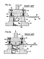
- Figs. 3a and 3b are schematic views in section of a cutting die set illustrating the method used to produce decorative shapes in a prior process.
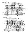
- Figs. 4a and 4b are schematic views in section of a 2-working station cutting die set for producing decorative shapes by a method embodying the present invention.
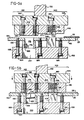
- Figs. 5a and 5b are schematic views in section of another cutting die set for producing decorative shapes by a method embodying the present invention.
- a typical shape comprises a substrate 10 which is coated on the back side with a layer of adhesive 12.
- a sheet of release paper 14 releasably laminated to the layer of adhesive 12.
- the top or graphic surface 13 of the substrate 10 is preferably provided with a layer or primer or a subbing layer 16 on which a decorative design or insignia 18 is painted or silk screen printed.
- This design is overcoated with a clear plastics coating or layer 20 which beautifies the image and imparts wear and weather resistance to the object.
- Plastic coating 20 is optionally overcoated with a further protective film 22 such as a film of polyethylene.
- FIG. 2 A composite for mass producing these shapes is shown in Figure 2 wherein an array of designs 24 is formed on graphic face 25 of a sheet of substrate 26.
- the design areas present a laminar construction as in Figure 1, however, for simplicity only the plastics coat 28 is separately shown and the laminated substrate is generally designated 26 with the understanding that it represents the laminated substrate structure as shown in Fig. 1.
- Alternatives to coating local areas of the substrate are to coat the entire sheet of substrate 26 or only the individual designs 24 with plastics.
- the designs may be formed with an edge, dyke or other shapes defining a peripheral edge which halts the flow of the plastics at the design edge.
- the simpler technique however is to deposit an amount of plastics on the design which, when it flows to completion, coats the design and a small amount of the area which immediately surrounds it, as shown in Fig. 2.
- the substrate upon which the fluent plastics is coated may be as plastics or metal foil, preferably an aluminium foil 0.076 to 0.50 mm (0.003 to 0.020 inch) thick.
- the foil substrate is decorated with an appropriate design or series of designs. More commonly, a series of designs in the form of individual emblems or plaque shapes will be applied to the foil sheet. With a metal foil, the series of designs is preferably applied by silk screen or lithographic printing then the design is enhanced by embossing select areas; although other means for forming the decorative designs may also be used.
- the foil may be embossed to give a three dimensional effect to the emblem.
- any suitable primer may be used, such as a silane primer.
- the decorated-primer substrate is then placed upon a vacuum mat which is situated upon a horizontal vacuum table such as that shown in our U.S. Patent No. 4,034,708. Vacuum is drawn against the bottom surface of the foil substrate through the mat to hold the substrate flat and horizontal.
- the flow characteristics of the fluent plastics and the liquid wettability of the foil substrate are used to control the spread of the plastics so that it is contiguous with predetermined areas of the foil substrate as well as being uniformly thick. It is also possible to control the plastics flow by use of sharply defined peripheral sides for the substrate or defined areas of the substrate as disclosed in U.S. Patent No. 4,292,827.
- Flow coating is a path-wise deposition. That is, a multiple orifice nozzle (or nozzles) is passed over the decorated-primed surface of the foil substrate at a steady speed as the substrate is held stationary.
- the number of orifices used may vary depending on the width of the path to be laid down.
- the thickness sought is between approximately 0.50 to 1.0 mm (0.020 to 0.040 inch).
- the plastic is preferably a fluent polyurethane of two component parts (polyol and isocyanate) which are mixed immediately prior to coating and cure upon heating.
- a polyurethane of this type is disclosed in our U. S. Patent No. 4,100,010.
- That mixture is one of a polyether polyol component ("A"), which may be a difunctional, trifunctional and/or tetrafunctional polypropylene glycol containing a suitable catalyst, and a diisocyanate component ("B") such as an aliphatic diisocyanate.
- a catalyst such as a lead or mercury material is used since it promotes a slow cure at room temperature so as to allow time for full flow of the liquid polyurethane before setting.
- an example of the diisocyanate is Hylene W from E. I.
- the polyether polyol may be one or more of the Pluracol materials (P-410 or TP-440) from BASF Wyandotte. It may also be a polyether-polyester polyol combination, use of the polyester polyol making the cured polyurethane more flexible.
- the ratio of components A:B is preferably 50-60:40-50.
- a polyester polyol or polylactone polyol could be used in place of the polyether polyol.
- the polyurethane may be compounded from among components listed in the patent as is known to give a more flexible cured plastic.
- the bond to the substrate remains strong, it is desirable to have a somewhat flexible plastic coat so that the emblem or plaque may be conformed.
- some decorative automobile panels are applied to a curved surface.
- the present invention it is possible to conform the cured plastic coated panel to that surface.
- curing will be by irradiation with infra-red or ultra-violet light.
- the polyurethane compounds mentioned above are heat curable and, thus, infra-red lamps are used; although, obviously other heat sources may also be used. Still, it is desirable to get a through cure, i.e., heat from both the top and bottom of the coated foil.
- the preferred vacuum table arrangement of U. S. Patent No. 4,034,708 makes this possible because of a capability of heating or cooling it.
- the infra-red lamps themselves as the heat source for both top and bottom heating This may be done by using an I.R. absorptive mat as the vacuum mat. The mat will, then pick up heat from the infra-red radiation and conduct it back from the bottom through the coated foil substrate.
- the coated substrate is cooled and removed from the vacuum table.
- Individual emblem or plaque shapes are stamped out by a cutting die around the particular emblem or plaque shape. It has been found that, by providing a steel rule knife edge around the mouth of the cavity of the cutting die, and by preventing the coated substrate from bowing while die cutting the decorative shape, it is possible to obtain a shape which is essentially flat (except in areas where the shape has been pre-embossed to give depth to the decorative pattern) and which has a sharp vertical edge which resists delamination and provides good weather and wear resistance.
- the shapes are cut from the coated, laminated substrate using a die set such as the illustrated in Figs. 4 or 5. The die sets shown in Figs.
- a conventional cutting die set is shown in Fig. 3a.
- This die set comprises a punch holder 40 which is mounted in die cutting relation with a die holder 42.
- Punch holder 40 is coupled to a press ram (not shown) by shank 43, and die holder 42 is clamped or otherwise mounted to the press bed at ears 45.
- the punch holder 40 and die holder 42 are aligned by a plurality of guide posts and guide bushings (not shown).
- the press is mechanically actuated but a hydraulic press may also be used.
- a male punch 46 is mounted on the punch holder 40 with a surrounding stripper plate 44.
- the plate 44 contiguously frames the male punch 46 and is mounted for resilient reciprocation on a set of spring-shoulder screw assemblies comprising die springs 49 and 51 carried on shoulder screws or stripper bolts 48 and 50.
- a set of spring-shoulder screw assemblies comprising die springs 49 and 51 carried on shoulder screws or stripper bolts 48 and 50.
- two shoulder screws are shown, another pair of shoulder screws, located on the back side of the stripper plate, is not seen in these schematic sectional views.
- a threaded connection is provided between the shoulder screws 48 and 50 and the stripper plate 44.
- the stripper plate 44 holds the substrate in place during the cutting operation and cleans any selvage clinging to the punch 46.
- the position of the stripper plate may be lowered or raised by inserting a shim under the shoulder or body of the shoulder screw. To increase spring pressure,a shim may be inserted under the die spring or a higher pressure die spring can be used.
- Die holder 42 carries a female die 45 having a cutting edge 56, a die face 58 and a female die cavity 60.
- the female die 54 is positioned on the die holder 42 such that the female die cavity 60 opens on an outlet passage 62 formed in the holder 42.
- Shapes having a laminar construction such as shown in Fig. 1 are cut from a substrate by positioning the substrate 26 on the face 58 of the female die 54 with its graphic side 25 down and its design area in alignment with the mouth or cutting edge 56 of the die.
- the press is closed as shown in Fig. 3b, the substrate 26 is engaged by the stripper plate 44 and the punch 46.
- the punch 46 descends into the die cavity 60, the springs 49 and 51 on the shoulder screws 48 and 50 are compressed and the area of the substrate contiguous with the design is engaged by the stripper plate 44. Due to the relative softness of the layers on each side of the substrate 26, the substrate is pulled into the die cavity 60 and bows under the punch 46 as shown by the bow 68 in Fig. 3b.
- the die set comprises a punch holder 80, a die holder 82, a right working station 84 and a left working station 86.
- the shape is cut from and reinserted into the substrate 26.
- the cut shape is ejected from the substrate by a punch.
- the die set is mounted to the press ram by shank 85 and fixed to the press bed at ears 87.
- the right station 84 includes a female cutting die 90 which is mounted on the die holder 82.
- the female cutting die comprises a die cavity 92 in which a pressure platform 94 is resiliently mounted on a spring and shoulder screw assembly comprising spring 96 and shoulder screw 98.
- a plurality of spring shoulder screw assemblies are used to support the platform depending on the size of the shape cut.
- the shoulder screw 98 is threaded and screws into the platform 94.
- the platform in the die cavity and the compression of the spring 96 can be adjusted to provide just enough pressure to prevent the substrate from bowing without deforming the plastics coating over the graphic using shims in a manner analogous to that previously described for the stripper plate 44 in Fig. 3.
- the mouth of the die cavity 92 is equipped with and defined by a knife edge 100 which projects upwardly towards the upper face of the die 90.
- a punch 102 is mounted on the punch holder 80 and framed by a contiguous stripper plate 104.
- the stripper plate 104 is mounted on a set of four spring and shoulder screw assemblies wherein two assemblies are shown in the view with springs 106 carried on shoulder screws 108 which are threaded at the bottom where they connect to the stripper plate 104. Engagement of the stripper plate is adjusted as earlier described.
- the left station 86 comprises a second punch 110 mounted on the punch holder 80 and a female die 112 having a die face 114 which is mounted on the die holder 82 such that the die cavity 116 opens into a collection passage 120 formed in the die holder 82.
- Punch 110 is framed by a stripper plate 115 which is mounted for reciprocating movement on spring-shoulder screw assemblies 115 a and 115 b .
- Plate 115 functions analogous to plate 104 and holds the substrate flat as the cut shape is ejected and removes selvage from the punch 110.
- the pressure platform 94 is shown resiliently mounted on a spring and shoulder screw assembly, those skilled in the art will understand that the spring and shoulder screw assemblies illustrated herein may be replaced by other types of resilient mounts including rubber blocks and compressed air or hydraulically actuated cylinders.
- Fig. 4b Operation of the die press is shown in Fig. 4b wherein the substrate 26, which typically has an array of cured plastics coated designs thereon as shown in Fig. 2, is positioned in the right station 84 with its graphic side 25 facing the punch 102 and its design contiguous with the cutting edge 100 which bounds the mouth of the die cavity 92.
- the pitch of the designs on the substrate is such that a second cut design is simultaneously located over the die 112 in the left station as the first design is cut.
- the size of the die assemblies in the right and left working stations usually dictate that a third cut design be idle between the right and left stations as the cutting and ejecting operations proceed.
- the punch 102 engages the substrate 26 and presses it against the pressure platform 94.
- the tension in the spring 96 is such that the pressure platform 94 resists the descent of punch 102 with sufficient tension to prevent the substrate 26 from bowing under application of the punch 102 without otherwise scratching, compressing or deforming the design shape 24 (Fig. 2) or its clear plastics coating 28.
- the compression spring 96, and therefore the pressure applied by the platform 94 is adjusted using shims or through the selection of the die spring, such that the substrate is not distorted by cutting and the cut shape or part is returned to the selvage for carriage to the ejecting station. If the spring pressure is too high, the part is distorted, if it is too low, the part is not returned to the selvage.
- the platform 94 is depressed below the upper edge of the knife edge 100 and the substrate 26 is urged against the knife edge 100 whereupon a decorative shape 126 is cut from the substrate 26 and forced into the female die cavity 92.
- the stripper plate 104 engages the portions of the substrate 26 surrounding the shape 126 to prevent those portions from angling around the knife edge 100 and to assist in obtaining a sharply cut vertical edge.
- the press After cutting decorative shape 126 from the substrate 26, the press opens and punch 102 disengages the substrate. As pressure on platform 94 is released, the platform returns to its original position slightly above the edge of the knife edge 100 and insodoing reinserts the shape 126 into the substrate 26. At this time, stripper plate 104 is still in pressing engagement with the substrate such that the substrate does not cling to the male punch 102 and the platform 94 is able to reinsert the shape 126 into the substrate without lifting the substrate off the face of the female cutting die.
- Fig. 4 illustrates a completely automated system in which decorative shapes are continuously cut at the right working station and ejected from the substrate at the left working station with each stroke of the die set, the ejection operation at the second station can be performed manually. In this case, a cutting die set having only the right station 84 produces a substrate from which the cutout shapes can be pushed, for example, by hand.
- Figs. 5a and 5b illustrate another embodiment of the invention.
- the female cutting die is mounted above the punch and moves into a stationery die punch.
- the die set is a two working station die set having a cutting station 140 on the right and a punching station 142 on the left.
- the punching station 142 may be replaced by its manual equivalent.
- the cutting station 140 and the punching station 142 share a upper die set holder 144.
- a female cutting die 146 is mounted on the upper holder 144 in die cutting relation with a male punch 148 mounted on the lower die set holder 150.
- the upper holder 144 is coupled by shank 152 to a mechanical press (not shown) by a ram cap, and the lower holder 150 is secured to the press bed. Alignment of the upper and lower holders is typically by guide posts, also not shown.
- the female die 146 includes a die cavity 154 in which a pressure platform 156 is resiliently mounted on a spring and shoulder screw assembly comprising a spring 158 carried on a shoulder screw 160 wherein the shoulder screw has a threaded connection with platform 156.
- a plurality of spring and shoulder screw assemblies may be used instead of the one shown depending on the design of the shape.
- Lower holder 150 supports a resilient table 162 mounted on a set of spring and shoulder screw assemblies 164 each assembly comprising a spring 166 carried on a shoulder screw 168 which is mounted by a threaded connection to the table 162.
- the height of the table 162 and the tension of the springs can be adjusted using shims as previously discussed.
- the number of spring and shoulder screw assemblies supporting the table 162 will vary depending upon the size and design of the emblem or plaque being cut. In the embodiments shown six shoulder screws are used - the three seen in the view and three on the backside.
- the male punch 148 is mounted on the lower holder 150 through an opening 147 in the table 162 such that resilient reciprocal movement is permitted between the table 162 and the punch 148 and the table 162 strips any substrate hanging on the punch 148 after cutting.
- the substrate 26 is positioned in station 140 with its graphic side 25 facing the punch 148 and its plastic coated design aligned with the cutting edge of a steel rule knife edge 155 with which the mouth of the die cavity 154 is equipped.
- the upper holder 144 moves the die 146 into engagement with the substrate 26 and the punch 148 whereupon the pressure platform 156 is engaged and prevents the substrate from bowing.
- the pressure platform 156 is depressed with some depression of the resilient table 162 on the die holder 150 whereupon the shape is cut from the substrate.
- the resilient table 162 maintains the substrate 26 in contact with the face of the female die 146 such that the pressure platform 156 can reinsert the shape into the substrate as it returns to its original undepressed position.
- the left station 142 comprises a male punch 174 mounted on upper holder 144, the resilent table 162, and a channel 188 which is formed by a channel-forming wall 178 which is slidably received in passage 180 formed in the lower holder 150.
- the substrate is resiliently engaged between the table 162 and a stripper plate 182 which frames the punch 174 and is mounted resiliently and adjustably on spring and shoulder screw assemblies 184.
- the male punch 174 subsequently pushes the cut shape 183 through the opening 176 in table 162 and into the channel 188 formed by the channel-forming wall 178 from which it falls out of the press through the passage 180 in the lower holder.
Landscapes
- Engineering & Computer Science (AREA)
- Mechanical Engineering (AREA)
- Perforating, Stamping-Out Or Severing By Means Other Than Cutting (AREA)
Claims (6)
- Verfahren zum Herstellen dekorativer Formen (126, 183), welches aufweist: Flüssigbeschichten der Orberfläche eines horizontal gelagerten Substrates (26), welches eine Reihe von individuellen Gestaltungen (18, 24) hat, die darauf vorgesehen sind, mit einem klaren, zähflüssigen Kunststoff (20, 28), Aushärten des flüssigen Kunststoffes (20, 28) und Ausstanzen der kunststoffbeschichteten Formen aus dem Substrat entlang der Grenzen der Gestaltungen, wobei das Verfahren einschließt:
Ausstanzen jeder der Gestaltungen an einer ersten Arbeitsstation (84, 140), welche einen Stanzstempel (102, 148) aufweist, der mit einer Stanzmatritze (90, 146) zusammenwirkt, die eine Stanzvertiefung (92, 154) hat, deren Öffnung von einer Messerkante (100, 153) eines Stahllineals festgelegt wird, welche in Richtung auf dem Stempel vorspringt, und eine Druckplatte (94, 156) aufweist, welche in der Stanzvertiefung montiert und in Richtung des Stempels durch eine federnd nachgebende Befestigungseinrichtung (96, 98; 158, 160) vorgespannt ist,
Ausstanzen jeder Form durch Anwenden von Stempel und Matritze auf den gegenürberliegenden Oberflächen des Substrates und indem der Stempel und die Messerkante so zusammenwirken, daß sie die Form aus dem Substrat ausstanzen, während die Form mit der Plattform mit ausreichender Kraft gegen die Vorderfläche des Stempels gehalten wird, um zu verhindern, daß sich die Form verbiegt, und dadurch Herstellen einer scharfen Schneidkante an der Form, und Bewirken, daß die Form und die Platte in die Matritzenvertiefung gedrückt werden, und
dann Wiedereinsetzen jeder der ausgestanzten Formen in das Substrat (26) mit Hilfe der federnd nachgebend montierten Platte (94, 156),
Transportieren der in das Substrat wieder eingesetzten Formen zu einer zweiten Arbeitsstation (86, 142), und
Ausstoßen der Formen (126, 183) aus dem Substrat (26) bei der zweiten Arbeitsstation (86, 142). - Verfahren nach Anspruch 1, welches den Eingriff mit den Abschnitten des Substrates einschließt, die jede Form umgeben, während sie aus dem Substrat ausgestanzt und wieder eingesetzt wird, mit einer Abstreifplatte (104, 162), die federnd nachgebend um jeden Stempel herum montiert ist, so daß die Platte als Pahmen an den Stempel angrenzt.
- Verfahren nach Anspruch 1 oder 2, wobei die zweite Arbeitsstation einen zweiten Stempel (110, 174) aufweist der mit einem Halteteil (112, 162) zusammenwirkt, welcher eine den Stempel aufnehmende Öffnung (116, 176) hat, die darin ausgebildet ist, wobei das Verfahren die Anwendung des zweiten Stempels und des Halteteiles auf gegenüberliegenden Seiten des Substrates unter Ausrichtung mit jeder gestanzten Form aufweist, und Bewirken, daß der letztgenannte Stempel die Form aus dem Substrat in die Öffnung ausstößt.
- Verfahren nach Anspruch 3, welches den Eingriif der Abschnitte des Substrates, die jede gestanzte Form umgeben, mit einer Abstreifplatte (115, 182), während die Form aus dem Substrat ausgestoßen wird, einschließt, wobei die Abstreifplatte federnd nachgebend um den zweiten Stempel herum montiert ist derart, daß die Platte den Stempel in seiner Kontur (angrenzend) umrahmt.
- Verfahren nach einem der vorstehenden Ansprüche, einschließlich des Anwendens einer Schicht eines Klebstoffs (12) und einer Ablösbeschichtung (14) auf der Oberfläche des Substrates gegenüber von dem Kunststoff (20).
- Verfahren nach Anspruch 1, wobei die dekorative Form unter Verwendung eines Stanzsatzes ausgestanzt wird, wobei der Stanzsatz aufweist:
ein erstes Stützteil (144), auf welchem die Stanzmatritze (146) und ein Ausstoßstempel (174) gemeinsam montiert sind,
ein zweites Stützteil (150), auf welchem ein Tisch (162) federnd nachgebend über eine federnd nachgebende Befestigungseinrichtung (164, 166, 168) montiert ist,
wobei der Tisch eine erste Öffnung (147) und eine zweite Öffnung (176) hat,
der Stanzstempel (148) auf dem zweiten Stützteil (150) durch die erste Öffnung in dem federnd nachgebend montierten Tisch montiert ist, und
ein Durchgang (180) in dem zweiten Stützteil (150) gebildet ist, welcher mit der zweiten Öffnung (176) in dem federnd montierten Tisch (162) ausgerichtet ist,
wobei die ersten und zweiten Stützteile für eine Hin- und Herbewegung relativ zueinander montiert sind, die Stanzmatritze (146) in Stanzdruckbeziehung zu dem Stanzstempel (148) steht und der Ausstoßstempel (174) in Stanzdruckbeziehung zu der zweiten Öffnung (146) in dem federnd montierten Tisch (162) steht derart, daß beim Aufbringen eines Druckes, um die Verschiebung der Stützteile in Richtung aufeinanderzu zu bewirken, an der Stanzmatritze das Substrat zwischen der federnd montierten Druckplatte (156) und dem Stanzstempel (148) mit einer Druckkraft erfaßt wird, welche vermeidet, daß das Substrat verbogen wird, ohne es anderweitig zu verformen, wobei die Druckplattform herabgedrückt wird und die Form aus dem Substrat ausgestanzt und in die Stanzvertiefung eingedrückt wird, und daß beim Lösen des Druckes der Stanzstempel mit dem Substrat außer Eingriff tritt und die federnd montierte Druckplatte die Form wieder in das Substrat einsetzt,
und wobei die wieder eingesetzte gestanzte Form bei dem Ausstoßstempel (174) aus dem Substrat aus- und durch den Durchgang (180) in dem zweiten Stützteil gestoßen wird.
Priority Applications (3)
| Application Number | Priority Date | Filing Date | Title |
|---|---|---|---|
| US06/301,494 US4599253A (en) | 1981-09-14 | 1981-09-14 | Method for making decorative emblems and the like and shapes prepared by that method |
| DE8686303510T DE3680329D1 (de) | 1986-05-08 | 1986-05-08 | Methode zur herstellung von dekorativen emblemen und dergleichen sowie auf diese weise hergestellte gegenstaende. |
| EP19860303510 EP0244524B1 (de) | 1986-05-08 | 1986-05-08 | Methode zur Herstellung von dekorativen Emblemen und dergleichen sowie auf diese Weise hergestellte Gegenstände |
Applications Claiming Priority (1)
| Application Number | Priority Date | Filing Date | Title |
|---|---|---|---|
| EP19860303510 EP0244524B1 (de) | 1986-05-08 | 1986-05-08 | Methode zur Herstellung von dekorativen Emblemen und dergleichen sowie auf diese Weise hergestellte Gegenstände |
Publications (2)
| Publication Number | Publication Date |
|---|---|
| EP0244524A1 EP0244524A1 (de) | 1987-11-11 |
| EP0244524B1 true EP0244524B1 (de) | 1991-07-17 |
Family
ID=8196001
Family Applications (1)
| Application Number | Title | Priority Date | Filing Date |
|---|---|---|---|
| EP19860303510 Expired EP0244524B1 (de) | 1981-09-14 | 1986-05-08 | Methode zur Herstellung von dekorativen Emblemen und dergleichen sowie auf diese Weise hergestellte Gegenstände |
Country Status (2)
| Country | Link |
|---|---|
| EP (1) | EP0244524B1 (de) |
| DE (1) | DE3680329D1 (de) |
Families Citing this family (3)
| Publication number | Priority date | Publication date | Assignee | Title |
|---|---|---|---|---|
| CN101578184B (zh) * | 2007-01-11 | 2014-07-09 | 北方雕刻公司 | 单一标识的加工方法和产品 |
| CN114871319B (zh) * | 2022-04-26 | 2022-12-27 | 安徽弘伟环境装备有限公司 | 一种冷凝水盘冲压装置 |
| CN121869920B (zh) * | 2026-03-19 | 2026-06-30 | 山西宏坊电力金具制造有限公司 | 一种钢帽加工用整形装置及其使用方法 |
Family Cites Families (5)
| Publication number | Priority date | Publication date | Assignee | Title |
|---|---|---|---|---|
| US4166403A (en) * | 1977-08-10 | 1979-09-04 | Houdaille Industries, Inc. | Method of making a rigidly supported molded plastics material punch guide and stripper |
| US4292827A (en) * | 1978-05-08 | 1981-10-06 | The D. L. Auld Company | Method for making decorative emblems |
| FR2507949A1 (fr) * | 1981-06-22 | 1982-12-24 | Jaeger | Procede et dispositif de decoupage de pieces dans une plaque par poinconnage, et produit intermediaire de la mise en oeuvre du procede |
| FR2507948A1 (fr) * | 1981-06-22 | 1982-12-24 | Jaeger | Procede et dispositif de decorticage de pieces decoupees dans une plaque |
| US4599253A (en) * | 1981-09-14 | 1986-07-08 | The D. L. Auld Company | Method for making decorative emblems and the like and shapes prepared by that method |
-
1986
- 1986-05-08 EP EP19860303510 patent/EP0244524B1/de not_active Expired
- 1986-05-08 DE DE8686303510T patent/DE3680329D1/de not_active Expired - Fee Related
Also Published As
| Publication number | Publication date |
|---|---|
| EP0244524A1 (de) | 1987-11-11 |
| DE3680329D1 (de) | 1991-08-22 |
Similar Documents
| Publication | Publication Date | Title |
|---|---|---|
| US4599253A (en) | Method for making decorative emblems and the like and shapes prepared by that method | |
| US4356617A (en) | Decorative emblems and method for making same | |
| US4386123A (en) | Article of manufacture and methods of manufacturing | |
| CA1276418C (en) | Process and apparatus for manufacturing embossed articles of synthetic resin | |
| JP4371638B2 (ja) | 成形要素を作製するための方法および装置 | |
| US6280823B1 (en) | Foil-covered plastic part and method of making same | |
| CA2882969A1 (en) | Method for providing a lamination film with adhesive, method for applying hot melt, application, lamination plant and method for upgrading such a plant | |
| US5480688A (en) | Shaped flexible decorative articles and method for making same | |
| US8080124B2 (en) | Production method of a molded article | |
| US6869663B1 (en) | Method of selectively coating a wood composite, and coated wood composite | |
| JPS59232818A (ja) | 圧空金型成形方法 | |
| EP0102205B1 (de) | Vorrichtung zur Herstellung einer gestaltaufweisenden Folie mit einer Kappe aus gegossenem Kunststoff | |
| EP0244524A1 (de) | Methode zur Herstellung von dekorativen Emblemen und dergleichen sowie auf diese Weise hergestellte Gegenstände | |
| EP4074502A1 (de) | Dreidimensionales zierteil und verfahren zur herstellung davon | |
| JPH0311614B2 (de) | ||
| US4263085A (en) | Tape product for forming indicia, and process and apparatus for producing same, and products produced using such tape product | |
| CN115489170B (zh) | 一种超薄铝复合电视机背板及生产方法 | |
| CA2243114A1 (en) | Method of producing lens sheet and projection screen | |
| CN208759873U (zh) | 汽车热压成型内饰件的三层生产模具 | |
| JPS6316996A (ja) | 装飾体の製造方法 | |
| GB2060485A (en) | Manufacture of Badges, Medallions and the Like | |
| CN109323163B (zh) | 背光模组制造方法 | |
| GB2127750A (en) | Plates embossed with symbols | |
| JP3300870B2 (ja) | ドアトリム真空成形装置 | |
| CN216466900U (zh) | 一种可油墨回收的印花加工设备 |
Legal Events
| Date | Code | Title | Description |
|---|---|---|---|
| PUAI | Public reference made under article 153(3) epc to a published international application that has entered the european phase |
Free format text: ORIGINAL CODE: 0009012 |
|
| AK | Designated contracting states |
Kind code of ref document: A1 Designated state(s): DE FR GB IT |
|
| 17P | Request for examination filed |
Effective date: 19880428 |
|
| 17Q | First examination report despatched |
Effective date: 19890904 |
|
| GRAA | (expected) grant |
Free format text: ORIGINAL CODE: 0009210 |
|
| AK | Designated contracting states |
Kind code of ref document: B1 Designated state(s): DE FR GB IT |
|
| ITF | It: translation for a ep patent filed | ||
| REF | Corresponds to: |
Ref document number: 3680329 Country of ref document: DE Date of ref document: 19910822 |
|
| ET | Fr: translation filed | ||
| PLBE | No opposition filed within time limit |
Free format text: ORIGINAL CODE: 0009261 |
|
| STAA | Information on the status of an ep patent application or granted ep patent |
Free format text: STATUS: NO OPPOSITION FILED WITHIN TIME LIMIT |
|
| 26N | No opposition filed | ||
| PGFP | Annual fee paid to national office [announced via postgrant information from national office to epo] |
Ref country code: FR Payment date: 19930409 Year of fee payment: 8 |
|
| PGFP | Annual fee paid to national office [announced via postgrant information from national office to epo] |
Ref country code: DE Payment date: 19930414 Year of fee payment: 8 |
|
| PGFP | Annual fee paid to national office [announced via postgrant information from national office to epo] |
Ref country code: GB Payment date: 19930430 Year of fee payment: 8 |
|
| PG25 | Lapsed in a contracting state [announced via postgrant information from national office to epo] |
Ref country code: GB Effective date: 19940508 |
|
| GBPC | Gb: european patent ceased through non-payment of renewal fee |
Effective date: 19940508 |
|
| PG25 | Lapsed in a contracting state [announced via postgrant information from national office to epo] |
Ref country code: FR Effective date: 19950131 |
|
| PG25 | Lapsed in a contracting state [announced via postgrant information from national office to epo] |
Ref country code: DE Effective date: 19950201 |
|
| REG | Reference to a national code |
Ref country code: FR Ref legal event code: ST |
|
| PG25 | Lapsed in a contracting state [announced via postgrant information from national office to epo] |
Ref country code: IT Free format text: LAPSE BECAUSE OF NON-PAYMENT OF DUE FEES;WARNING: LAPSES OF ITALIAN PATENTS WITH EFFECTIVE DATE BEFORE 2007 MAY HAVE OCCURRED AT ANY TIME BEFORE 2007. THE CORRECT EFFECTIVE DATE MAY BE DIFFERENT FROM THE ONE RECORDED. Effective date: 20050508 |