EP0244597A1 - Dispositif de transfert hydraulique de corps et emploi de ce dispositif - Google Patents
Dispositif de transfert hydraulique de corps et emploi de ce dispositif Download PDFInfo
- Publication number
- EP0244597A1 EP0244597A1 EP87103578A EP87103578A EP0244597A1 EP 0244597 A1 EP0244597 A1 EP 0244597A1 EP 87103578 A EP87103578 A EP 87103578A EP 87103578 A EP87103578 A EP 87103578A EP 0244597 A1 EP0244597 A1 EP 0244597A1
- Authority
- EP
- European Patent Office
- Prior art keywords
- channel
- conveying
- liquid
- delivery
- resistance
- Prior art date
- Legal status (The legal status is an assumption and is not a legal conclusion. Google has not performed a legal analysis and makes no representation as to the accuracy of the status listed.)
- Withdrawn
Links
- 238000001816 cooling Methods 0.000 claims abstract description 17
- 239000007788 liquid Substances 0.000 claims description 46
- 238000010438 heat treatment Methods 0.000 claims description 6
- 239000012530 fluid Substances 0.000 claims description 2
- 230000001954 sterilising effect Effects 0.000 abstract description 7
- 238000004659 sterilization and disinfection Methods 0.000 abstract description 7
- 230000002706 hydrostatic effect Effects 0.000 description 3
- 230000001105 regulatory effect Effects 0.000 description 3
- 239000000110 cooling liquid Substances 0.000 description 2
- 238000009413 insulation Methods 0.000 description 2
- 238000004806 packaging method and process Methods 0.000 description 2
- 238000012856 packing Methods 0.000 description 2
- 238000010586 diagram Methods 0.000 description 1
- 238000007710 freezing Methods 0.000 description 1
- 230000008014 freezing Effects 0.000 description 1
- 238000011144 upstream manufacturing Methods 0.000 description 1
- XLYOFNOQVPJJNP-UHFFFAOYSA-N water Substances O XLYOFNOQVPJJNP-UHFFFAOYSA-N 0.000 description 1
Images
Classifications
-
- A—HUMAN NECESSITIES
- A23—FOODS OR FOODSTUFFS; TREATMENT THEREOF, NOT COVERED BY OTHER CLASSES
- A23B—PRESERVATION OF FOODS, FOODSTUFFS OR NON-ALCOHOLIC BEVERAGES; CHEMICAL RIPENING OF FRUIT OR VEGETABLES
- A23B2/00—Preservation of foods or foodstuffs, in general
- A23B2/40—Preservation of foods or foodstuffs, in general by heating loose unpacked materials
- A23B2/42—Preservation of foods or foodstuffs, in general by heating loose unpacked materials while they are progressively transported through the apparatus
- A23B2/46—Preservation of foods or foodstuffs, in general by heating loose unpacked materials while they are progressively transported through the apparatus with transport through tubes
- A23B2/465—Preservation of foods or foodstuffs, in general by heating loose unpacked materials while they are progressively transported through the apparatus with transport through tubes in solid state
-
- A—HUMAN NECESSITIES
- A23—FOODS OR FOODSTUFFS; TREATMENT THEREOF, NOT COVERED BY OTHER CLASSES
- A23B—PRESERVATION OF FOODS, FOODSTUFFS OR NON-ALCOHOLIC BEVERAGES; CHEMICAL RIPENING OF FRUIT OR VEGETABLES
- A23B2/00—Preservation of foods or foodstuffs, in general
- A23B2/20—Preservation of foods or foodstuffs, in general by heating materials in packages which are progressively transported, continuously or stepwise, through the apparatus
Definitions
- the invention relates to a device according to the preamble of claim 1 and to a use of the device according to claim 11.
- the object of the invention is to improve a device of the type mentioned in the introduction so that the disadvantages mentioned are avoided.
- the object is achieved according to the invention by the features of the characterizing part of claim 1.
- the device it is possible to reduce the pressure in a delivery channel in a simple manner in such a way that a body can leave the delivery channel practically without pressure, even if, for example, delivery is from top to bottom.
- flow resistances can be generated by designing the device according to claim 2.
- An embodiment according to claim 3 is advantageous.
- an embodiment according to claim 4 is particularly advantageous.
- the resistance values can be increased by an embodiment of the guide channel according to claim 5.
- a resistance range can even be achieved in an embodiment according to claim 6.
- the resistance elements are configured according to claim 7, wherein in particular an adjustability of the lamellae enables further control of the resistance value.
- Such slats can be pivoted or extended and retracted. It is advantageous if this adjustability is carried out manually or by motor, so that continuous readjustment is possible if necessary.
- the device is designed according to claim 9, wherein the secondary liquid circuit enables a further control of the pressure in the device.
- the secondary liquid flow can be superimposed directly on the first liquid flow, it also being possible to design the device according to claim 10, in which case design according to claim 8 is advantageous.
- the delivery channel contains flow resistances to reduce the pressure of the liquid in some areas, it is possible to replace the pressure previously caused by the hydrostatic column by a hydrodynamic pressure of the delivery liquid, which can then be reduced again in those areas of the delivery channel in which the flow resistances are arranged.
- This measure means that high towers can be dispensed with, so that compact, relatively low systems can be built. This simplifies the design effort for scaffolding and solves the problems of insulation with simpler means.
- Such a system also has the decisive advantage that the pressure in the system can be regulated by the flow pressure of the conveying liquid, as a result of which the system can be simplified and adapted to changing packaging properties and changing heat treatment conditions.
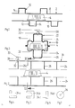
- FIG. 1 shows a conveying channel 2 in which packings 4 are conveyed as bodies with a liquid flow.
- Flow resistors 12 which are designed as pockets 14 pointing outwards, are arranged on the conveying channel 2 on opposite sides 8 and 10.
- FIGS. 2 and 3 show a further delivery channel 16, which on opposite sides 18, 20 has secondary channels 24 serving as flow resistors 22, in which resistance elements 26 are arranged transversely to the direction of flow.
- These resistance elements 26 can either be permanently installed in the secondary duct 24 or be adjustable, as is indicated for the resistance element 26a.
- the adjustable resistance element 26a has an axis 28 to which a handle 30 is attached.
- a locking screw 32 is used to secure the position of the selected setting of the resistance element 26.
- the adjustability can also be achieved by extending and retracting resistance elements. It is particularly expedient if the setting can be easily achieved by hand or by motor, so that there is continuous pressure control.
- Figures 4 to 7 show different resistance elements transverse to the direction of flow.
- the resistance element 34a of FIG. 4 is L-shaped.
- the resistance element 34b of FIG. 5 has a U-shape.
- the resistance element 34c of Figure 6 is bar-shaped.
- the resistance element 34d of FIG. 7 has the shape of a circular disk with a central through hole 36. Numerous other shapes of the resistance elements are also possible.
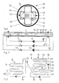
- FIGS. 8 and 9 show a further delivery channel 38, which is formed from a cylindrical jacket tube 40, in which a guide channel 42 for the packs 4 is arranged as an insert.
- the guide channel 42 contains guide strips 44 in order to keep the conveying resistance of the pack 4 as small as possible.
- the guide channel 42 is analogous to the exemplary embodiment of Figures 2 and 3 on opposite sides 46, 48 equipped with flow resistors 50 which are formed in the form of secondary channels 52 with resistance elements 54.
- the guide channel 42 contains openings 56, via which the interior 58 of the guide channel 42 communicates with the space 60 between the guide channel 42 and the casing tube 40.
- the space 60 can also or even exclusively contain resistance elements not shown in detail.
- a first liquid circuit 62 is connected to the conveying channel 38, which feeds a liquid stream upstream into the guide channel 42 and draws it downstream.
- the liquid circuit 62 contains a pump 64 and a control valve 66 with which the flow rate of the liquid can be regulated.
- a second liquid circuit 68 can also open into the guide channel 42 or be connected to the jacket pipe 40 and open into the space 60 between the jacket pipe 40 and the guide channel 42.
- This liquid circuit also contains a pump 70 and a control valve 72 in order to regulate the liquid flow and thus the flow resistance. While the first liquid circuit 62 serves primarily to convey the packs 4 in the guide channel 42, the second liquid circuit 68 regulates the pressure reduction by changing the amount of the liquid.
- Both liquid circuits can influence the flow resistance individually or together, which counteracts the delivery pressure of the liquid flow.
- a third liquid circuit 73 with a pump and regulating valve and, if appropriate, heat exchangers, such as heating or cooling, can be connected to the casing tube 40 and serve primarily for heat transfer.
- FIG. 10 shows the diagram of an overall system.
- packs are fed into a conveying channel 76 which conveys the packs on the one hand through a sterilization area 78 and on the other hand through a cooling area 80 to a free outlet 82.
- a lock 84 is arranged between the sterilization area 78 and the cooling area 80 and is of the type known from DE-PS 21 49 122, for example.
- the sterilization area 78 and the cooling area 80 each have their own liquid circuit 86, 88.
- the liquid circuit 88 of the cooling area 80 corresponds to the first liquid circuit 62 of the type described in FIG. 9, which contains the delivery or cooling liquid trapped at the outlet 82. for example water, feeds the feed channel 76 again at the beginning of the cooling area 80 via a line 90 and a pump 92.
- the cooling liquid can optionally be cooled by means of a cooling device, not shown.
- resistance areas 94, 96 of the type shown in FIG. 9 are arranged, which are connected to a second liquid circuit 97, which corresponds to the second liquid circuit 68 in FIG.
- the liquid of the second liquid circuit 97 is fed via a line 98 by means of a Pump 100 withdrawn and fed via a control valve 102 and line 104 to the first resistance area 94.
- the liquid is drawn off via a connecting line 106 and fed in again at the beginning of the resistance area 96.
Landscapes
- Life Sciences & Earth Sciences (AREA)
- Engineering & Computer Science (AREA)
- Wood Science & Technology (AREA)
- Zoology (AREA)
- Chemical & Material Sciences (AREA)
- Food Science & Technology (AREA)
- Polymers & Plastics (AREA)
- Food Preservation Except Freezing, Refrigeration, And Drying (AREA)
Applications Claiming Priority (2)
| Application Number | Priority Date | Filing Date | Title |
|---|---|---|---|
| CH137386 | 1986-04-08 | ||
| CH1373/86 | 1986-04-08 |
Publications (1)
| Publication Number | Publication Date |
|---|---|
| EP0244597A1 true EP0244597A1 (fr) | 1987-11-11 |
Family
ID=4208900
Family Applications (1)
| Application Number | Title | Priority Date | Filing Date |
|---|---|---|---|
| EP87103578A Withdrawn EP0244597A1 (fr) | 1986-04-08 | 1987-03-12 | Dispositif de transfert hydraulique de corps et emploi de ce dispositif |
Country Status (2)
| Country | Link |
|---|---|
| US (1) | US4863377A (fr) |
| EP (1) | EP0244597A1 (fr) |
Families Citing this family (4)
| Publication number | Priority date | Publication date | Assignee | Title |
|---|---|---|---|---|
| US5546849A (en) * | 1995-03-06 | 1996-08-20 | North Carolina State University | Hydrostatic heating apparatus |
| CA2320352A1 (fr) * | 1998-02-05 | 1999-08-12 | The Penn State Research Foundation | Dispositif de segmentation de flux |
| NL1022693C2 (nl) * | 2003-02-14 | 2004-08-17 | Tno | Continu thermisch proces voor het behandelen van grove voedseldeeltjes en voedseldeeltjes die verkrijgbaar zijn met het proces volgens de uitvinding. |
| FR2856044A1 (fr) * | 2003-06-13 | 2004-12-17 | Daniel Gaignoux | Procede et installation pour le transport d'objets dans un flux de liquide |
Citations (7)
| Publication number | Priority date | Publication date | Assignee | Title |
|---|---|---|---|---|
| DE190133C (fr) * | ||||
| NL6911760A (fr) * | 1968-08-14 | 1970-02-17 | ||
| DE2044802A1 (en) * | 1970-09-10 | 1972-03-16 | Neiss O | Water sterilizer system - sterilizing liquids or solids in sealed containers, esp food stuffs |
| FR2155152A5 (fr) * | 1971-09-28 | 1973-05-18 | Hero Conserven | |
| US4073226A (en) * | 1976-09-27 | 1978-02-14 | Innovative Patent Trust | Processing apparatus |
| FR2501631A1 (fr) * | 1981-03-16 | 1982-09-17 | Gatineau Jacques | Procede de sterilisation en continu de boites de conserve et installation pour la mise en oeuvre de ce procede |
| FR2506734A1 (fr) * | 1981-06-02 | 1982-12-03 | Neuweiler Ag | Installation pour le transfert d'objets, notamment de recipients remplis de produits |
Family Cites Families (7)
| Publication number | Priority date | Publication date | Assignee | Title |
|---|---|---|---|---|
| US3168298A (en) * | 1961-07-03 | 1965-02-02 | Norton Co | Tunnel kiln and method of operation |
| US3172647A (en) * | 1963-03-26 | 1965-03-09 | Bickley Furnaces Inc | Continuous kiln |
| JPS5118205B2 (fr) * | 1972-03-03 | 1976-06-08 | ||
| US3902382A (en) * | 1974-03-14 | 1975-09-02 | Curtis Noll Corp | Calibration gauge for key duplicating machine |
| FR2405448B1 (fr) * | 1977-10-07 | 1985-06-28 | Welko Ind Spa | Installation pour le controle de la conduite des fours a rouleaux pour la cuisson de matieres ceramiques ou similaires |
| US4588378A (en) * | 1983-11-18 | 1986-05-13 | Chugai Ro Co., Ltd. | Continuous heat treating furnace for metallic strip |
| US4522586A (en) * | 1983-11-29 | 1985-06-11 | Price Frank C | Thermal conditioning of material in containers |
-
1987
- 1987-03-12 EP EP87103578A patent/EP0244597A1/fr not_active Withdrawn
-
1988
- 1988-06-07 US US07/205,000 patent/US4863377A/en not_active Expired - Fee Related
Patent Citations (7)
| Publication number | Priority date | Publication date | Assignee | Title |
|---|---|---|---|---|
| DE190133C (fr) * | ||||
| NL6911760A (fr) * | 1968-08-14 | 1970-02-17 | ||
| DE2044802A1 (en) * | 1970-09-10 | 1972-03-16 | Neiss O | Water sterilizer system - sterilizing liquids or solids in sealed containers, esp food stuffs |
| FR2155152A5 (fr) * | 1971-09-28 | 1973-05-18 | Hero Conserven | |
| US4073226A (en) * | 1976-09-27 | 1978-02-14 | Innovative Patent Trust | Processing apparatus |
| FR2501631A1 (fr) * | 1981-03-16 | 1982-09-17 | Gatineau Jacques | Procede de sterilisation en continu de boites de conserve et installation pour la mise en oeuvre de ce procede |
| FR2506734A1 (fr) * | 1981-06-02 | 1982-12-03 | Neuweiler Ag | Installation pour le transfert d'objets, notamment de recipients remplis de produits |
Also Published As
| Publication number | Publication date |
|---|---|
| US4863377A (en) | 1989-09-05 |
Similar Documents
| Publication | Publication Date | Title |
|---|---|---|
| DE19536116A1 (de) | Wärmeübertrager für ein Kraftfahrzeug | |
| DE3327179A1 (de) | Verdampfer | |
| DE3021246A1 (de) | Plattenwaermetauscher | |
| DE2648719A1 (de) | Druckmessvorrichtung | |
| EP3489603A1 (fr) | Echangeur de chaleur | |
| DE4404922C1 (de) | Peripher gebohrte Walze zur Wärmebehandlung von Bahnmaterial | |
| DE2333839A1 (de) | Stroemungsdrosseleinrichtung | |
| DE2707134A1 (de) | Vorrichtung zur durchflussregelung | |
| EP0876564B1 (fr) | Raccord de tuyaux | |
| EP2636958A2 (fr) | Répartiteur de circuit de chauffage avec vase de découplage hydraulique intégré | |
| DE3002712C2 (fr) | ||
| EP3339750A1 (fr) | Système d'alimentation en fluide et de circulation de fluide | |
| EP2180226A1 (fr) | Système de distribution de fluide modulaire | |
| EP0244597A1 (fr) | Dispositif de transfert hydraulique de corps et emploi de ce dispositif | |
| EP0021161A1 (fr) | Dispositif de jonction pour corps creux plats | |
| EP0109032B1 (fr) | Installation de chauffage à distance avec un dispositif de raccordement | |
| EP3822569B1 (fr) | Echangeur de chaleur | |
| DE3100582A1 (de) | Druck-steuerventil | |
| DE3210718A1 (de) | Vorrichtung zur durchflussregulierung | |
| EP1157755A2 (fr) | Distributeur à buses pour le refroidissement ou le décalaminage de matériaux allongés métalliques, en particulier de produits laminés | |
| EP0144029B1 (fr) | Tuyau de refroidissement pour section de refroidissement pour refroidir rapidement du fil laminé ou du matériel à barres | |
| EP4089357B1 (fr) | Echangeur de chaleur | |
| DE3023094C2 (de) | Vorrichtung zum Erzeugen von Dampf | |
| DE19637575A1 (de) | Standardisiertes Rohrelement | |
| DE2519803C2 (de) | Vorrichtung zum Wärmeaustausch |
Legal Events
| Date | Code | Title | Description |
|---|---|---|---|
| PUAI | Public reference made under article 153(3) epc to a published international application that has entered the european phase |
Free format text: ORIGINAL CODE: 0009012 |
|
| AK | Designated contracting states |
Kind code of ref document: A1 Designated state(s): BE CH DE FR GB IT LI NL |
|
| 17P | Request for examination filed |
Effective date: 19871205 |
|
| 17Q | First examination report despatched |
Effective date: 19890203 |
|
| STAA | Information on the status of an ep patent application or granted ep patent |
Free format text: STATUS: THE APPLICATION IS DEEMED TO BE WITHDRAWN |
|
| 18D | Application deemed to be withdrawn |
Effective date: 19900105 |
|
| RIN1 | Information on inventor provided before grant (corrected) |
Inventor name: GAIGNOUX, DANIEL Inventor name: SIEVI, HERBERT |