EP0244664A2 - Dispositif électronique de mesure pour système de détermination de la dureté - Google Patents
Dispositif électronique de mesure pour système de détermination de la dureté Download PDFInfo
- Publication number
- EP0244664A2 EP0244664A2 EP87105350A EP87105350A EP0244664A2 EP 0244664 A2 EP0244664 A2 EP 0244664A2 EP 87105350 A EP87105350 A EP 87105350A EP 87105350 A EP87105350 A EP 87105350A EP 0244664 A2 EP0244664 A2 EP 0244664A2
- Authority
- EP
- European Patent Office
- Prior art keywords
- stylus
- measuring rod
- dial gauge
- measuring
- boom
- Prior art date
- Legal status (The legal status is an assumption and is not a legal conclusion. Google has not performed a legal analysis and makes no representation as to the accuracy of the status listed.)
- Granted
Links
Images


Classifications
-
- G—PHYSICS
- G01—MEASURING; TESTING
- G01N—INVESTIGATING OR ANALYSING MATERIALS BY DETERMINING THEIR CHEMICAL OR PHYSICAL PROPERTIES
- G01N3/00—Investigating strength properties of solid materials by application of mechanical stress
- G01N3/40—Investigating hardness or rebound hardness
- G01N3/42—Investigating hardness or rebound hardness by performing impressions under a steady load by indentors, e.g. sphere, pyramid
-
- G—PHYSICS
- G01—MEASURING; TESTING
- G01N—INVESTIGATING OR ANALYSING MATERIALS BY DETERMINING THEIR CHEMICAL OR PHYSICAL PROPERTIES
- G01N33/00—Investigating or analysing materials by specific methods not covered by groups G01N1/00 - G01N31/00
- G01N33/38—Concrete; Lime; Mortar; Gypsum; Bricks; Ceramics; Glass
- G01N33/388—Ceramics
Definitions
- the invention relates to an electronic digital dial gauge according to the preamble of claim 1.
- the invention is therefore based on the object to provide an electronic digital dial indicator for hardness testers, which corresponds to the dimensions of a mechanical dial gauge and which therefore allows a direct exchange of the mechanical dial gauge against the electronic dial gauge with the least possible assembly effort.
- the measuring transducer In order to accommodate the relatively complicated electronic measuring system in the small space available for the dial gauge, the measuring transducer must be kept relatively small in size and measure very precisely. This is possible in the embodiment according to the invention. Accurate measurement sets an exact, i.e. relatively long guidance of the stylus ahead. This is opposed to the fact that the stylus cannot be guided concentrically through the inductive measuring coil. Accordingly, the displacement sensor is arranged in parallel next to the stylus, and the control core, for example a ferrite core or the like, arranged concentrically in the measuring coil, which can also be designed as a coil system, is therefore coupled to the stylus via the cantilever.
- the control core for example a ferrite core or the like
- the measuring rod consists of ceramic material and the control core, which is in the form of a ferrite core, is embedded in the ceramic material.
- the exact guidance of the measuring rod with the control core in the measuring coil is advantageously achieved in accordance with Claim 4 in that the cavity of the measuring coil is designed as an exact linear guide for the measuring rod with control core which is precisely adapted to the diameter of the inside diameter of the linear guide.
- the inevitable manufacturing tolerances of the dial gauge are thus eliminated, and on the other hand the displacement of the stylus is transferred exactly to the control core.
- the measuring accuracy is also greatly increased because neither the twisting play of the stylus still distance and guide errors due to manufacturing tolerances can exert an influence on the position of the control core.
- a high linearity of the measuring system can be achieved with extremely small tolerances.
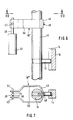
- a laterally protruding locking pin 12 is anchored in the stylus 10 and is slidably guided in a groove 14 of a guide rail 16 running in the longitudinal direction of the stylus 10. This results in anti-rotation of the stylus 10 with little play.
- a first section 18 of a vertically projecting arm is anchored at another point on the stylus, near the end of which a disk 20 is fastened which has a radial cutting edge 22.
- a second section 24 of the boom which runs parallel to the first section 18 and overlaps it. In the overlapping area, the two sections 18 and 24 of the boom are held together non-positively by an elastic O-ring 26.
- a measuring rod 28 made of ceramic material is fastened near its end in such a way that it extends parallel to the stylus 10.
- the measuring rod passes through the cavity 30 of a measuring coil 32 and carries in this area an inductive control core 34 designed as a ferrite core.
- the cavity 30 is an exact linear guide formed for the measuring rod 28, the diameter of the measuring rod being precisely adapted to the clear width of the linear guide.
- a longitudinal displacement of the stylus 10 is transferred exactly and without play to the control core 34 via the cutting edge 22, with any games and manufacturing tolerances that may occur being absorbed by the semi-cardanic, elastic connecting member 20, 22, 26.
- the locking pin 12 is not attached directly to the stylus 10, but protrudes in one piece from the end of a one-piece bracket 18 ⁇ .
- the boom 18 ⁇ has a transverse bore 36 in which the stylus 10 is fixed by means of a screw 38.
- the opposite end of the boom 18 ⁇ lies on a rounded crest 40 at the end of the measuring rod 28.
- the measuring coil 32 and the parts provided in it are designed in the same way as in the embodiment shown in FIG. 1 and therefore do not have to be shown again here.
- the measuring rod In the section outside the measuring coil 32, the measuring rod carries a stop ring 42.
- An elastic clamp 44 holds the stop ring 42 and the arm 18 ⁇ together in a force-locking manner.
- the boom 18 ⁇ is in one piece in shape a band made of spring steel or material with similar bending properties and arranged upright with respect to the longitudinal direction of the stylus 10.
- the spring steel strip 18 ' has on the side of the stylus 10 remote from the measuring rod 28 a curved section 46, the curvature of which is slightly less than the curvature of the outer circumference of the stylus 10.
- the section 46 is therefore only linearly on the stylus 10 and is in this Area attached to the stylus 10 by a screw 48.
- the two arms 50 of the arm 18 'pointing in the direction of the measuring rod 28 carry near their opposite ends a pin 52 each with a tip 56 pressed into a recess 54 of the measuring rod 28 by the resilient action of the arms 50.
- a circular spring steel band which is arranged upright for the longitudinal extension of the stylus 10, is also provided as a one-piece arm 18 ⁇ . It is always in a line shape on the side of the stylus 10 and the measuring rod 28 pointing away from one another and is fastened in these areas in each case by a screw 38 or 58 to the stylus 10 or to the measuring rod 28.
- this embodiment is mainly suitable for compensating torsional backlash and distance tolerance, while it is not possible to compensate for guide errors. With very precise guidance of the measuring rod 28, however, this is not necessary in many cases, so that this simplified embodiment is sufficient.
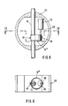
- FIGS. 8 and 9 show a housing 60 surrounding the entire dial gauge with the parts essential to the invention and the other parts (not shown) of an electronic digital dial gauge, the size of which largely corresponds to the mechanical dial gauges previously used and used for this purpose.
- the electronic parts of the dial gauge, not shown, are connected to the measuring coil 32 in a manner known per se. From this representation of the housing 60 it can be seen that an existing mechanical dial gauge can be replaced at any time by an electronic digital dial gauge according to the invention, with no additional space requirement having to be created and the assembly effort being kept within narrow limits. An existing hardness tester can be retrofitted with an electronic dial gauge according to the invention at any time.
- the parts 12, 14, 16 for securing the stylus against rotation are not shown in this embodiment.
- the measuring rod 28 stands upwards from the arm 18 ⁇ , which would also be readily possible in the other embodiments without impairing the mode of operation.
Landscapes
- Immunology (AREA)
- Pathology (AREA)
- Life Sciences & Earth Sciences (AREA)
- Chemical & Material Sciences (AREA)
- Analytical Chemistry (AREA)
- Biochemistry (AREA)
- General Health & Medical Sciences (AREA)
- General Physics & Mathematics (AREA)
- Health & Medical Sciences (AREA)
- Physics & Mathematics (AREA)
- A Measuring Device Byusing Mechanical Method (AREA)
- Measurement Of Length, Angles, Or The Like Using Electric Or Magnetic Means (AREA)
- Adhesives Or Adhesive Processes (AREA)
- Compositions Of Macromolecular Compounds (AREA)
- Investigating Strength Of Materials By Application Of Mechanical Stress (AREA)
- Investigating Or Analyzing Materials By The Use Of Ultrasonic Waves (AREA)
- Tires In General (AREA)
Priority Applications (1)
| Application Number | Priority Date | Filing Date | Title |
|---|---|---|---|
| AT87105350T ATE64203T1 (de) | 1986-05-09 | 1987-04-10 | Elektronische messuhr fuer haertepruefer. |
Applications Claiming Priority (2)
| Application Number | Priority Date | Filing Date | Title |
|---|---|---|---|
| DE3615696 | 1986-05-09 | ||
| DE19863615696 DE3615696A1 (de) | 1986-05-09 | 1986-05-09 | Elektronische messuhr fuer haertepruefer |
Publications (3)
| Publication Number | Publication Date |
|---|---|
| EP0244664A2 true EP0244664A2 (fr) | 1987-11-11 |
| EP0244664A3 EP0244664A3 (en) | 1988-01-27 |
| EP0244664B1 EP0244664B1 (fr) | 1991-06-05 |
Family
ID=6300495
Family Applications (1)
| Application Number | Title | Priority Date | Filing Date |
|---|---|---|---|
| EP87105350A Expired - Lifetime EP0244664B1 (fr) | 1986-05-09 | 1987-04-10 | Dispositif électronique de mesure pour système de détermination de la dureté |
Country Status (4)
| Country | Link |
|---|---|
| US (1) | US4773258A (fr) |
| EP (1) | EP0244664B1 (fr) |
| AT (1) | ATE64203T1 (fr) |
| DE (2) | DE3615696A1 (fr) |
Families Citing this family (2)
| Publication number | Priority date | Publication date | Assignee | Title |
|---|---|---|---|---|
| US5133210A (en) * | 1990-02-06 | 1992-07-28 | The University Of Maryland | Thermal expansion driven indentation stress-strain system |
| US6691564B2 (en) | 2002-04-23 | 2004-02-17 | Rams Rockford Products, Inc. | Hardness tester |
Family Cites Families (14)
| Publication number | Priority date | Publication date | Assignee | Title |
|---|---|---|---|---|
| DE803378C (de) * | 1948-10-02 | 1951-04-02 | Hommel G M B H H | Haertepruefeinrichtung |
| DE934198C (de) * | 1952-10-17 | 1955-10-13 | Georg Reicherter Kommanditgese | Rockwellhaertepruefer |
| US3295365A (en) * | 1965-01-04 | 1967-01-03 | Monsanto Co | Extensometer |
| US3657921A (en) * | 1969-12-31 | 1972-04-25 | American Chain & Cable Co | Method and apparatus for testing the hardness of materials |
| DE2513085C2 (de) * | 1975-03-25 | 1982-04-01 | Kernforschungszentrum Karlsruhe Gmbh, 7500 Karlsruhe | Vorrichtung zum linearen Ausmessen der Axialdehnung von Proben |
| FR2368704A1 (fr) * | 1976-10-19 | 1978-05-19 | Anvar | Appareil pour l'examen d'une eprouvette metallique |
| US4118975A (en) * | 1976-12-16 | 1978-10-10 | Kabushiki Kaisha Akashi Seisakusho | Loading shaft positioning apparatus for hardness tester |
| US4036048A (en) * | 1977-01-21 | 1977-07-19 | Webster Robert A | Hardness testing device |
| FR2382688A1 (fr) * | 1977-03-04 | 1978-09-29 | Oreal | Appareil de mesure de durete |
| CH628985A5 (it) * | 1978-12-15 | 1982-03-31 | Alfred Ernst | Misuratore di durezza con dispositivo di blocco di sicurezza. |
| AT359315B (de) * | 1979-01-18 | 1980-11-10 | Hubert Dipl Ing Aschinger | Mikrohaertepruefer |
| US4246777A (en) * | 1979-08-03 | 1981-01-27 | Owens-Illinois, Inc. | Test device for containers |
| JPS589044A (ja) * | 1981-06-24 | 1983-01-19 | Sumitomo Rubber Ind Ltd | ゴム、プラスチツク等の硬度測定方法およびそれに表いる硬度計 |
| US4691559A (en) * | 1985-02-07 | 1987-09-08 | Helmut Fischer | Device for measuring the properties of solid materials which can be derived from the behavior of a penetrating body |
-
1986
- 1986-05-09 DE DE19863615696 patent/DE3615696A1/de not_active Ceased
-
1987
- 1987-04-10 DE DE8787105350T patent/DE3770518D1/de not_active Expired - Lifetime
- 1987-04-10 AT AT87105350T patent/ATE64203T1/de not_active IP Right Cessation
- 1987-04-10 EP EP87105350A patent/EP0244664B1/fr not_active Expired - Lifetime
- 1987-05-06 US US07/046,389 patent/US4773258A/en not_active Expired - Fee Related
Also Published As
| Publication number | Publication date |
|---|---|
| DE3615696A1 (de) | 1987-11-12 |
| US4773258A (en) | 1988-09-27 |
| DE3770518D1 (de) | 1991-07-11 |
| EP0244664A3 (en) | 1988-01-27 |
| ATE64203T1 (de) | 1991-06-15 |
| EP0244664B1 (fr) | 1991-06-05 |
Similar Documents
| Publication | Publication Date | Title |
|---|---|---|
| WO2002023558A2 (fr) | Element de detection de deplacement | |
| DE2724858A1 (de) | Laengenmessgeraet mit korrektureinrichtung | |
| DE3518259A1 (de) | Wegmessinstrument | |
| EP0517653B1 (fr) | Tête de mesure palpeur | |
| EP0303831A2 (fr) | Palpeur dynamique | |
| EP0163070A2 (fr) | Palpeur de mesure pour des dents | |
| DE7811664U1 (de) | Geraet zum anzeigen von messwerten | |
| DE3026353C2 (fr) | ||
| EP0244664B1 (fr) | Dispositif électronique de mesure pour système de détermination de la dureté | |
| DE4418829A1 (de) | Verzahnungsprüfgerät | |
| EP0649519B1 (fr) | Dispositif permettant de mesurer la force de man uvre d'aiguillage | |
| DE3632964A1 (de) | Piezoelektrisches stellglied | |
| DE2714521A1 (de) | Vorrichtung zur exakten lagebestimmung von zwei gegeneinander geradlinig verschieblichen teilen | |
| DE3438718A1 (de) | Praezisionskupplung fuer die winkelgetreue uebertragung rotatorischer bewegungen | |
| DE3440221C2 (de) | Meßuhr mit digitaler Anzeigeeinheit | |
| DE69717573T2 (de) | Mechanismus zum Vergrössern der Amplitude einer Bewegung | |
| DE2832038A1 (de) | Linearmikrometer | |
| DE2704396C2 (de) | Vorrichtung zur Feinpositionierung einer Trägerstange für eine Sonde o.dgl. | |
| DE3045416C2 (fr) | ||
| DE3608392C2 (fr) | ||
| DE19928151B4 (de) | Meßtaster | |
| DE29815452U1 (de) | Meßschieber | |
| DE3246246A1 (de) | Potentiometer | |
| DE4004486C2 (fr) | ||
| DE2042155B2 (de) | Schieblehre mit Meßuhr |
Legal Events
| Date | Code | Title | Description |
|---|---|---|---|
| PUAI | Public reference made under article 153(3) epc to a published international application that has entered the european phase |
Free format text: ORIGINAL CODE: 0009012 |
|
| AK | Designated contracting states |
Kind code of ref document: A2 Designated state(s): AT BE CH DE ES FR GB GR IT LI LU NL SE |
|
| PUAL | Search report despatched |
Free format text: ORIGINAL CODE: 0009013 |
|
| AK | Designated contracting states |
Kind code of ref document: A3 Designated state(s): AT BE CH DE ES FR GB GR IT LI LU NL SE |
|
| 17P | Request for examination filed |
Effective date: 19880528 |
|
| 17Q | First examination report despatched |
Effective date: 19891023 |
|
| GRAA | (expected) grant |
Free format text: ORIGINAL CODE: 0009210 |
|
| AK | Designated contracting states |
Kind code of ref document: B1 Designated state(s): AT BE CH DE ES FR GB GR IT LI LU NL SE |
|
| PG25 | Lapsed in a contracting state [announced via postgrant information from national office to epo] |
Ref country code: IT Free format text: LAPSE BECAUSE OF FAILURE TO SUBMIT A TRANSLATION OF THE DESCRIPTION OR TO PAY THE FEE WITHIN THE PRE;WARNING: LAPSES OF ITALIAN PATENTS WITH EFFECTIVE DATE BEFORE 2007 MAY HAVE OCCURRED AT ANY TIME BEFORE 2007. THE CORRECT EFFECTIVE DATE MAY BE DIFFERENT FROM THE ONE RECORDED.SCRIBED TIME-LIMIT Effective date: 19910605 Ref country code: GR Free format text: LAPSE BECAUSE OF FAILURE TO SUBMIT A TRANSLATION OF THE DESCRIPTION OR TO PAY THE FEE WITHIN THE PRESCRIBED TIME-LIMIT Effective date: 19910605 Ref country code: GB Effective date: 19910605 Ref country code: BE Effective date: 19910605 Ref country code: NL Effective date: 19910605 Ref country code: SE Effective date: 19910605 |
|
| REF | Corresponds to: |
Ref document number: 64203 Country of ref document: AT Date of ref document: 19910615 Kind code of ref document: T |
|
| REF | Corresponds to: |
Ref document number: 3770518 Country of ref document: DE Date of ref document: 19910711 |
|
| PG25 | Lapsed in a contracting state [announced via postgrant information from national office to epo] |
Ref country code: ES Free format text: LAPSE BECAUSE OF FAILURE TO SUBMIT A TRANSLATION OF THE DESCRIPTION OR TO PAY THE FEE WITHIN THE PRESCRIBED TIME-LIMIT Effective date: 19910916 |
|
| EN | Fr: translation not filed | ||
| PG25 | Lapsed in a contracting state [announced via postgrant information from national office to epo] |
Ref country code: FR Effective date: 19911025 |
|
| NLV1 | Nl: lapsed or annulled due to failure to fulfill the requirements of art. 29p and 29m of the patents act | ||
| GBV | Gb: ep patent (uk) treated as always having been void in accordance with gb section 77(7)/1977 [no translation filed] | ||
| PLBE | No opposition filed within time limit |
Free format text: ORIGINAL CODE: 0009261 |
|
| STAA | Information on the status of an ep patent application or granted ep patent |
Free format text: STATUS: NO OPPOSITION FILED WITHIN TIME LIMIT |
|
| PG25 | Lapsed in a contracting state [announced via postgrant information from national office to epo] |
Ref country code: AT Effective date: 19920410 |
|
| PG25 | Lapsed in a contracting state [announced via postgrant information from national office to epo] |
Ref country code: LU Free format text: LAPSE BECAUSE OF NON-PAYMENT OF DUE FEES Effective date: 19920430 |
|
| 26N | No opposition filed | ||
| REG | Reference to a national code |
Ref country code: CH Ref legal event code: PUE Owner name: RAMBOLD MESSGERAETE GMBH |
|
| REG | Reference to a national code |
Ref country code: FR Ref legal event code: ST |
|
| PGFP | Annual fee paid to national office [announced via postgrant information from national office to epo] |
Ref country code: DE Payment date: 19950519 Year of fee payment: 9 |
|
| PGFP | Annual fee paid to national office [announced via postgrant information from national office to epo] |
Ref country code: CH Payment date: 19950720 Year of fee payment: 9 |
|
| PG25 | Lapsed in a contracting state [announced via postgrant information from national office to epo] |
Ref country code: CH Effective date: 19960430 Ref country code: LI Effective date: 19960430 |
|
| REG | Reference to a national code |
Ref country code: CH Ref legal event code: PL |
|
| PG25 | Lapsed in a contracting state [announced via postgrant information from national office to epo] |
Ref country code: DE Effective date: 19970101 |