EP0244709B1 - Dispositif d'affichage ou de signalisation - Google Patents
Dispositif d'affichage ou de signalisation Download PDFInfo
- Publication number
- EP0244709B1 EP0244709B1 EP87105992A EP87105992A EP0244709B1 EP 0244709 B1 EP0244709 B1 EP 0244709B1 EP 87105992 A EP87105992 A EP 87105992A EP 87105992 A EP87105992 A EP 87105992A EP 0244709 B1 EP0244709 B1 EP 0244709B1
- Authority
- EP
- European Patent Office
- Prior art keywords
- display
- pair
- rotation
- viewing direction
- display surface
- Prior art date
- Legal status (The legal status is an assumption and is not a legal conclusion. Google has not performed a legal analysis and makes no representation as to the accuracy of the status listed.)
- Expired
Links
- XEEYBQQBJWHFJM-UHFFFAOYSA-N Iron Chemical group [Fe] XEEYBQQBJWHFJM-UHFFFAOYSA-N 0.000 claims description 14
- 229910052742 iron Inorganic materials 0.000 claims description 6
- 239000000463 material Substances 0.000 claims description 5
- 230000004907 flux Effects 0.000 claims description 3
- 230000002441 reversible effect Effects 0.000 claims description 2
- 239000012858 resilient material Substances 0.000 claims 1
- 230000000295 complement effect Effects 0.000 description 5
- 230000000712 assembly Effects 0.000 description 4
- 238000000429 assembly Methods 0.000 description 4
- 238000003780 insertion Methods 0.000 description 3
- 230000037431 insertion Effects 0.000 description 3
- 241000282472 Canis lupus familiaris Species 0.000 description 2
- 239000000853 adhesive Substances 0.000 description 2
- 230000001070 adhesive effect Effects 0.000 description 2
- 238000013459 approach Methods 0.000 description 1
- 238000004040 coloring Methods 0.000 description 1
- 238000010276 construction Methods 0.000 description 1
- 230000008878 coupling Effects 0.000 description 1
- 238000010168 coupling process Methods 0.000 description 1
- 238000005859 coupling reaction Methods 0.000 description 1
- 230000005389 magnetism Effects 0.000 description 1
- 230000005415 magnetization Effects 0.000 description 1
- 239000002184 metal Substances 0.000 description 1
- 229910052751 metal Inorganic materials 0.000 description 1
- 238000000465 moulding Methods 0.000 description 1
- 230000000717 retained effect Effects 0.000 description 1
- 239000007787 solid Substances 0.000 description 1
- 238000004804 winding Methods 0.000 description 1
Images


Classifications
-
- G—PHYSICS
- G09—EDUCATION; CRYPTOGRAPHY; DISPLAY; ADVERTISING; SEALS
- G09F—DISPLAYING; ADVERTISING; SIGNS; LABELS OR NAME-PLATES; SEALS
- G09F9/00—Indicating arrangements for variable information in which the information is built-up on a support by selection or combination of individual elements
- G09F9/30—Indicating arrangements for variable information in which the information is built-up on a support by selection or combination of individual elements in which the desired character or characters are formed by combining individual elements
- G09F9/37—Indicating arrangements for variable information in which the information is built-up on a support by selection or combination of individual elements in which the desired character or characters are formed by combining individual elements being movable elements
- G09F9/375—Indicating arrangements for variable information in which the information is built-up on a support by selection or combination of individual elements in which the desired character or characters are formed by combining individual elements being movable elements the position of the elements being controlled by the application of a magnetic field
Definitions
- This invention relates to a display or indicating device having at least one display or indicating element.
- the device may have one such element or several such elements which are selectively operable to make letters or figures.
- the display device in Patent 4,223,464 has a display or indicating element having permanent magnets rotating at opposed ends of a pair of magnetic cores.
- the cores as described in the patent are of high coercivity material. These high coercivity cores have the advantage that their polarity may be switched, or ′set′, by a pulse of short duration shorter than and of duration independent of the time for the display element to move from one limiting position to the other.
- the display elements if accidentially displaced from their ′set′ position will tend to return to it.
- the high coercivity requires a relatively high increase in switching power, i.e. energizing coil current, to produce a relatively low increase in switching torque.
- ′sticking′ of the display element in its set position is a problem, it is difficult and expensive to raise the switching power to a level sufficient to overcome a sticking of the element.
- the result is a switchable display element wherein the increase in driving torque to switch the element from one position to the other is closely related to the increase in switching power applied. A tendency for an element to stick can thus be relatively easily avoided by increase of the coil energizing current.
- the duration of the switching pulse is increased and the element does not necessarily return to its ′set′ position after accidentical deflection, but rather magnetically latches in whichever of the limiting position it comes to rest.
- the viewing direction is the approximate centre of the solid angle defined by the limits of directions in which it is intended that the display device will be viewed.
- display position we mean a first limiting position in which the “display surface” (that is the contrasting surface) of the element is displayed in the viewing direction and by "obscured position” we mean a second limiting position in which the display surface is obscured in the viewing direction.
- flag we mean a member having a display surface which member is separable from and attachable to the element.
- the element uses two permanent magnets usually circular and coaxial with the rotation axis of the element and located opposite the free ends of the magnetic cores, which permanent magnets are locally magnetizable to form diametrically opposed north and south poles facing respective cores.
- Each of such poles has a complementary pole at the side of the permanent magnet remote from the cores. It is found that the strength of such magnets are increased if a soft iron bridge is provided on the side of the magnet remote from the cores to complete the magnetic circuit between the complementary locally magnetized poles.
- the display surface of the element is an elongate surface or flag having its longitudinal axis extending parallel to the rotational axis of the element.
- the display position the display surface is displayed in the viewing direction and is coloured to contrast with its background.
- the obscured position the element is rotated so that the display surface is obscured in the viewing direction.
- the greater the angle of rotation beyond 90° the wider the angle through which the element may be viewed without seeing the display surface in the obscured position.
- the closer the angle of rotation approaches 180° the more serious the reduction in the starting torque applied to the element upon switching between the first and second limiting positions.
- the compromise between these requirements is to choose an angle of rotation of about 135° and in any event between 125°-150°.
- the support for the element To attach the support for the element to a base plate, it is easier to design a support which projects from the base plate in a direction parallel to the viewing direction. In order, then, to obtain 135° rotation it is easier to slope the outer extent of the support, which is preferably a pillar, in the direction of rotation of the element from the display position toward the obscured position. This slope, which is at an angle of at least 35° and preferably is at an angle equal to the difference between the desired rotation and 90°, provides a convenient ′underhang′ to receive the display surface in the obscured position. Where the desired rotation is 135°, the angle of the slope of the outer extent to the inner extent of the pillar is therefore 45°.
- DE 27 35 254 A1 discloses a pillar extending at an oblique angle from a base plate, but which pillar does not incorporate inner and outer extents at an angle to one another in the manner of the preferred embodiment of the invention.
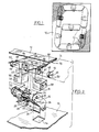
- Figure 1 shows a base plate 10 facing in the viewing direction ′V′ in ( Figure 5) and mounting seven display elements arranged to provide, by selective switching of the display elements, the digits 0 to 9.
- the upper left and lower right display elements are in their obscured positions, showing the backs of the flags 12 which backs correspond in colouring to the background, while the remaining elements are in their display positions with the display surfaces of the flags 12 contrasting with the background so that the number ′2′ is shown.
- Figure 2 shows the base plate 10 with a square aperture 14 in which the support, in the form of a pillar, for an element may be clipped.
- the pillar comprises opposed side plates 16 having an inner straight extent perpendicular to the base plate 10 and an outer straight extent sloping at 45° to the inner extent in what will turn out to be the direction of rotation of the element from its display position towards its obscured position.
- Inner and outer end walls 18 and 20 join the edges of opposed side walls to form a square in transverse section through the pillar. The end walls 18 and 20 stop a short distance outward of the beginning of the slope in the pillar.
- the pillar is attached to the plate 10 by resiliently inwardly deflectable dogs 22 inwardly projecting from end walls 18 and 20 and having outwardly facing shoulders 24 which, after such inward deflection insertion and release, engage the inner surface of the plate 10 to retain the pillar in position.
- the side walls are provided with inwardly diverging supports 27 which abuttingly meet the outer surface of the plate 10 to help maintain the pillar rigid.
- the dogs 22 may be positioned on the side walls and the supports 24 on the end walls.
- the side walls and end walls may be attached by adhesive or by other means as desired.
- a pair of low coercivity or soft iron cores 26 extend longitudinally and parallel between the side walls 16.
- Energizing coils 28 surround the cores 26 and are supplied with current from a source, not shown.
- Halfway between the cores 26, side walls 16 mount aligned outwardly projecting stub shafts 30 on which the element is to be mounted for rotation between the first and second limiting positions.
- the two stub shafts are replaced by a single central shaft extending between the side walls and projecting therefrom
- the outer edges of the side walls are provided with an rounded arc 32 over which the element may rotate and are shaped to provide, at each end a shoulder (34 and 36 respectively) which limits the movement of the element in its display and obscured positions, respectively.
- the element preferably comprises a rectilinear outer wall or crossbar 38 with a pair of opposed legs 40 extending inwardly therefrom at a spacing such that such legs may extend (and rotate) on each side of the pillar adjacent opposed side walls 16.
- Opposed circular apertures 42 are provided in the legs 40 of a size to receive generally cylindrical permanent magnets assemblies 44.
- the magnet assemblies are preferably slightly tapered to allow easy insertion in the apertures 42. In place, the magnet assemblies are held in place by adhesive or any other desired means.
- the magnetic assemblies are centrally apertured at 46 to rotatably to receive the stub shafts 30.
- the central apertures are preferably lined with low frication bearing material.
- the magnet assembly comprises a cylindrical high remanence high coercivity thicker portion 48, preferably nearer the free ends of cores 26 and a cylindrical low coercivity or soft iron thinner portion 50 farther from the free ends of cores.
- the high coercivity portion of each magnet assembly is locally magnetized at 52 and 54 parallel to the rotational axis to provide respectively diametrically opposed N and S poles nearer the coil free ends as best shown in Figure 4a. Since the magnetization is in the axial direction the N pole shown requires a complement south pole (not lettered) at the low coercivity layer 50; and the S pole shown requires a complement north pole (not lettered) at the low coercivity layer.
- the low coercivity layer 50 thus provides a short circuiting of the magnetic circuit between the complement poles. It is found that this arrangement greatly improves the flux density at the core -adjacent poles N and S, and the operation of the display element is thereby improved.
- the size of the magnet assembly is chosen so that the locally magnetized poles N and S are at each side of the pillar directly opposite the free ends of core 26.
- the inward ends of legs 40 are provided with axially projection abutments 56 and these are provided with axially open bores 58. These bores will be sized, larger or smaller as required, to balance the element, including the flag 12 about its rotational axis.
- cross bar 38 of the element are designed to act, in cooperation with the stop surfaces 34 and 36, to define the display position and obscured position, respectively.
- the inward surface 62 of the cross bar 38 contacts surface 34 at the display position and the edge 64 of the cross bar 38 contacts the surface 36 at the obscured position.
- the axially directed edges of cross bar 38 each form three axially directed projections being arranged to be disposed from each other in a direction generally transverse to the rotational axis and parallel to the display surface thereon.
- Central projection 66 is notched on its inward surface and outer projections 68 are notched on their upper surface to allow nesting of a resilient wire 70.
- the wire is provided with arms 72 and 74 extending transversely on each side of the element in a shallow, outwardly directed v. The unstressed attitude of the wire is such that it must be flexed to slightly narrow the v to fit into the notches of the projections 66, 68.
- the wires 70 are stressed when supported in the notches and will ′stand′ on the rotor so stressed, for insertion of the flag 12.
- the outer ends of the v arms are reversed turned in the outward direction through about 135° to receive the edges of the flag 12.
- the flags 12 shaped as any one of those shown in Figure 1 are elongate and are preferably parallel sided and designed to extend longitudinally on each side of the element.
- the flag 12 is constructed of resilient plastic or metal and alone at rest is designed to assume a concavo-convex shape slightly wider from edge to edge than the hooked ends of the v arms.
- the concave surface of the flag 12 is the ′display surface′ and is coloured (here with a light colour) to contrast with the background of the plate 10 and is displayed in the viewing direction on the display position of the element. (The solid line position of Figure 2).
- the convex surface of the flag 12 is coloured to correspond to the background, (and to those parts of the element and pillar exposed in the obscured position in Figure 5).
- the flag 12 is attached to the wires 70 as they ′stand′ on the rotor by flexing the flag 12 to increase its concavity and placing its opposed longitudinal edges in the exposed wire hooks. The flag 12 then unbends resiliently along its length and bears on the inside of the wire hooks and is securely retained in position. It will be noted that the extra stress provided on the wire hooks by the flag 70 increases the flexure pressure of the wire hooks on the projections, making the connection between the wire and the element more secure.
- the flag 12 may have any other shape with edges suitable for coupling to the wires 70.
- Two terminals 25 are attached to the molding side walls and are connected to the respective coils 28 which are connected in series.
- the coil winding and connection is such that adjacent outer ends of cores 28 are of opposite polarity and switchable by the pulses of coil current.
- Inward ends 29 of terminals 25 are connected to a source (not shown) of the current pulses.
- Figures 6 and 7 show the magnetism of the ends of the cores 26 at the end viewed in Figure 5.
- Figure 6 shows the rear ends of cores 26 magnetized to polarities S′ and N′ to attract the poles 52 and 54 of magnet 48 to the display position of the element as shown in the solid line position of Figure 5.
- the opposite ends of the cores 26 are each oppositely magnetized but the corresponding magnet 48 is oriented to produce identical magnetic torque to that shown.
- the coils 28 are pulsed to reverse the polarity of the cores 26 so that, with reference to Figure 5, the new N′ and S′ magnetized core ends attract the S and N poles 54 and 52 to swing the rotor 135° to the dotted line position of Figure 5.
- the remote end of the element and cores 26 will of course provide the same torque and in the same sense.
- the switching pulse in coils 28 must be maintained until the permanent magnet poles have latched to the respectively adjacent cores 26 in the new position.
Landscapes
- Physics & Mathematics (AREA)
- General Physics & Mathematics (AREA)
- Engineering & Computer Science (AREA)
- Theoretical Computer Science (AREA)
- Devices For Indicating Variable Information By Combining Individual Elements (AREA)
Claims (7)
Applications Claiming Priority (2)
| Application Number | Priority Date | Filing Date | Title |
|---|---|---|---|
| US857498 | 1977-12-05 | ||
| US06/857,498 US4744163A (en) | 1986-04-30 | 1986-04-30 | Seven bar module |
Publications (2)
| Publication Number | Publication Date |
|---|---|
| EP0244709A1 EP0244709A1 (fr) | 1987-11-11 |
| EP0244709B1 true EP0244709B1 (fr) | 1991-06-26 |
Family
ID=25326130
Family Applications (1)
| Application Number | Title | Priority Date | Filing Date |
|---|---|---|---|
| EP87105992A Expired EP0244709B1 (fr) | 1986-04-30 | 1987-04-24 | Dispositif d'affichage ou de signalisation |
Country Status (5)
| Country | Link |
|---|---|
| US (1) | US4744163A (fr) |
| EP (1) | EP0244709B1 (fr) |
| JP (1) | JP2851841B2 (fr) |
| CA (1) | CA1280891C (fr) |
| DE (2) | DE3770988D1 (fr) |
Families Citing this family (6)
| Publication number | Priority date | Publication date | Assignee | Title |
|---|---|---|---|---|
| US5208589A (en) * | 1990-07-23 | 1993-05-04 | Reynolds Eugene E | Magnetically controlled indicia display device |
| DE9112802U1 (de) * | 1991-10-15 | 1991-12-19 | Feist, Walter, 7730 Villingen-Schwenningen | Anzeigevorrichtung |
| US6278431B1 (en) * | 1996-11-18 | 2001-08-21 | Lite Vision Corporation | Magnetically operated display |
| US6212806B1 (en) * | 1998-05-29 | 2001-04-10 | Karl Adolf Krawinkel | Display apparatus |
| EP2069892B1 (fr) * | 2006-09-27 | 2013-03-13 | Bandit Inc. | Affichage magnétique pour montres |
| US20110158057A1 (en) * | 2009-04-02 | 2011-06-30 | Brewer Donald R | Magnetic display for watches |
Family Cites Families (24)
| Publication number | Priority date | Publication date | Assignee | Title |
|---|---|---|---|---|
| US3096594A (en) * | 1960-06-17 | 1963-07-09 | Allard Instr Corp | Variable exhibitor |
| US3363347A (en) * | 1966-11-09 | 1968-01-16 | Robert N. Benson | Visual indicator device |
| US3537197A (en) * | 1969-01-23 | 1970-11-03 | Ferranti Packard Ltd | Lever operated display device |
| DE2249125C2 (de) * | 1972-10-06 | 1974-11-07 | Camille Bauer Messinstrumente Ag, Wohlen (Schweiz) | Drucker mit einer Auswählanordnung für Druckelemente |
| US3914723A (en) * | 1974-07-15 | 1975-10-21 | Price Edison Inc | Positive action magnetic latching relay |
| GB1471094A (en) * | 1975-03-20 | 1977-04-21 | Pye Ltd | Electromagnetic indicator |
| JPS5344046A (en) * | 1976-10-04 | 1978-04-20 | Seikosha Kk | Indicating device |
| US4117478A (en) * | 1976-10-12 | 1978-09-26 | The Staver Company, Incorporated | Variable character display device |
| JPS5368197A (en) * | 1976-11-30 | 1978-06-17 | Nec Corp | Input device with indication |
| IT1076017B (it) * | 1977-02-01 | 1985-04-22 | Nuovo Pignone Spa | Perfezionamenti in un indicatore numerico elettromeccanico a sette segmenti |
| JPS53139997A (en) * | 1977-05-13 | 1978-12-06 | Nippon Telegr & Teleph Corp <Ntt> | Display panel |
| JPS5381148A (en) * | 1977-06-16 | 1978-07-18 | Seikosha Kk | Indicating apparatus |
| US4233382A (en) * | 1978-10-27 | 1980-11-11 | E. I. Du Pont De Nemours And Company | Electrostatic transfer of magnetically held toner images |
| US4308528A (en) * | 1978-12-28 | 1981-12-29 | Kienzle Apparate Gmbh | Electromechanically driven digital indicating device |
| US4223464A (en) * | 1979-03-22 | 1980-09-23 | Ferranti-Packard Limited | Display or indicator element |
| JPS57204581A (en) * | 1981-06-11 | 1982-12-15 | Masayuki Wakatake | Display unit |
| US4459587A (en) * | 1981-11-16 | 1984-07-10 | Benco Industries, Inc. | Motorized character rotation device and method of selective actuation |
| JPS58152678U (ja) * | 1982-04-06 | 1983-10-13 | 富士通機電株式会社 | 二面表示器 |
| US4566210A (en) * | 1983-06-13 | 1986-01-28 | Nei Canada Limited | Display device |
| JPS60125881A (ja) * | 1983-12-13 | 1985-07-05 | 富士通機電株式会社 | 回転表示器の磁気ダンパ− |
| FR2558288B1 (fr) * | 1984-01-12 | 1987-06-19 | Bodet Ets | Dispositif d'affichage a segments basculants |
| US4577427A (en) * | 1984-05-14 | 1986-03-25 | Nei Canada Limited | Display |
| FR2565015B1 (fr) * | 1984-05-23 | 1986-09-05 | Lafon Sa | Systeme d'affichage d'un segment, notamment utilise dans un affichage numerique telecommande |
| FI842209A7 (fi) * | 1984-06-01 | 1985-12-02 | Polarpro Oy | Visningselement. |
-
1986
- 1986-04-30 US US06/857,498 patent/US4744163A/en not_active Expired - Lifetime
-
1987
- 1987-04-22 CA CA000535305A patent/CA1280891C/fr not_active Expired - Lifetime
- 1987-04-24 EP EP87105992A patent/EP0244709B1/fr not_active Expired
- 1987-04-24 DE DE8787105992T patent/DE3770988D1/de not_active Expired - Lifetime
- 1987-04-24 DE DE198787105992T patent/DE244709T1/de active Pending
- 1987-04-28 JP JP62103388A patent/JP2851841B2/ja not_active Expired - Fee Related
Also Published As
| Publication number | Publication date |
|---|---|
| CA1280891C (fr) | 1991-03-05 |
| JPS62288887A (ja) | 1987-12-15 |
| DE3770988D1 (de) | 1991-08-01 |
| JP2851841B2 (ja) | 1999-01-27 |
| US4744163A (en) | 1988-05-17 |
| EP0244709A1 (fr) | 1987-11-11 |
| DE244709T1 (de) | 1988-06-09 |
Similar Documents
| Publication | Publication Date | Title |
|---|---|---|
| US4531318A (en) | Display or indicating element with bent core | |
| US4223464A (en) | Display or indicator element | |
| US3365824A (en) | Magnetically operated display or indicating device | |
| CA1240148A (fr) | Affichage a disques desaxes | |
| EP0244709B1 (fr) | Dispositif d'affichage ou de signalisation | |
| US4327357A (en) | Magnetic indicator assembly | |
| US5021773A (en) | Fibre optic display device | |
| WO1991006085A1 (fr) | Dispositif d'affichage fonctionnant au moyen d'aimants | |
| GB1568769A (en) | Variable character display device | |
| US3680083A (en) | Three position electromagnetic indicator | |
| US3444551A (en) | Magnetically operated display device having display elements in liquid suspension | |
| US4308528A (en) | Electromechanically driven digital indicating device | |
| GB2122795A (en) | Vane display or indicating device | |
| US3260871A (en) | Step motor for use with an indicator | |
| US4864264A (en) | Bistable toggling indicator | |
| US3678426A (en) | Electromagnetic indicator | |
| US3979747A (en) | Control circuit for a character segment display assembly | |
| EP0294151A1 (fr) | Eléments d'affichage matriciels changeables | |
| US3508256A (en) | Electromagnetic positioned indicator wheel | |
| US3560966A (en) | Electromagnetically operated display device | |
| US4616221A (en) | Electromagnetic display | |
| JPH0317335Y2 (fr) | ||
| US3412393A (en) | Electromagnetic indicator wheel structure having variable position stator | |
| RU1833914C (ru) | Индикатор | |
| JP2010113956A (ja) | コネクタ |
Legal Events
| Date | Code | Title | Description |
|---|---|---|---|
| PUAI | Public reference made under article 153(3) epc to a published international application that has entered the european phase |
Free format text: ORIGINAL CODE: 0009012 |
|
| AK | Designated contracting states |
Kind code of ref document: A1 Designated state(s): DE FR GB IT |
|
| ITCL | It: translation for ep claims filed |
Representative=s name: MODIANO & ASSOCIATI S.R.L. |
|
| EL | Fr: translation of claims filed | ||
| 17P | Request for examination filed |
Effective date: 19880210 |
|
| DET | De: translation of patent claims | ||
| 17Q | First examination report despatched |
Effective date: 19900312 |
|
| GRAA | (expected) grant |
Free format text: ORIGINAL CODE: 0009210 |
|
| AK | Designated contracting states |
Kind code of ref document: B1 Designated state(s): DE FR GB IT |
|
| REF | Corresponds to: |
Ref document number: 3770988 Country of ref document: DE Date of ref document: 19910801 |
|
| RAP2 | Party data changed (patent owner data changed or rights of a patent transferred) |
Owner name: DAYCO PRODUCTS CANADA INC. |
|
| ITF | It: translation for a ep patent filed | ||
| ET | Fr: translation filed | ||
| PLBE | No opposition filed within time limit |
Free format text: ORIGINAL CODE: 0009261 |
|
| STAA | Information on the status of an ep patent application or granted ep patent |
Free format text: STATUS: NO OPPOSITION FILED WITHIN TIME LIMIT |
|
| 26N | No opposition filed | ||
| REG | Reference to a national code |
Ref country code: GB Ref legal event code: IF02 |
|
| PGFP | Annual fee paid to national office [announced via postgrant information from national office to epo] |
Ref country code: GB Payment date: 20040524 Year of fee payment: 18 |
|
| PGFP | Annual fee paid to national office [announced via postgrant information from national office to epo] |
Ref country code: FR Payment date: 20040623 Year of fee payment: 18 |
|
| PGFP | Annual fee paid to national office [announced via postgrant information from national office to epo] |
Ref country code: DE Payment date: 20040626 Year of fee payment: 18 |
|
| PG25 | Lapsed in a contracting state [announced via postgrant information from national office to epo] |
Ref country code: IT Free format text: LAPSE BECAUSE OF NON-PAYMENT OF DUE FEES;WARNING: LAPSES OF ITALIAN PATENTS WITH EFFECTIVE DATE BEFORE 2007 MAY HAVE OCCURRED AT ANY TIME BEFORE 2007. THE CORRECT EFFECTIVE DATE MAY BE DIFFERENT FROM THE ONE RECORDED. Effective date: 20050424 Ref country code: GB Free format text: LAPSE BECAUSE OF NON-PAYMENT OF DUE FEES Effective date: 20050424 |
|
| PG25 | Lapsed in a contracting state [announced via postgrant information from national office to epo] |
Ref country code: DE Free format text: LAPSE BECAUSE OF NON-PAYMENT OF DUE FEES Effective date: 20051101 |
|
| GBPC | Gb: european patent ceased through non-payment of renewal fee |
Effective date: 20050424 |
|
| PG25 | Lapsed in a contracting state [announced via postgrant information from national office to epo] |
Ref country code: FR Free format text: LAPSE BECAUSE OF NON-PAYMENT OF DUE FEES Effective date: 20051230 |
|
| REG | Reference to a national code |
Ref country code: FR Ref legal event code: ST Effective date: 20051230 |