EP0244710A2 - Toit pour un four de fusion de verre ou d'un avant-bassin - Google Patents
Toit pour un four de fusion de verre ou d'un avant-bassin Download PDFInfo
- Publication number
- EP0244710A2 EP0244710A2 EP87106005A EP87106005A EP0244710A2 EP 0244710 A2 EP0244710 A2 EP 0244710A2 EP 87106005 A EP87106005 A EP 87106005A EP 87106005 A EP87106005 A EP 87106005A EP 0244710 A2 EP0244710 A2 EP 0244710A2
- Authority
- EP
- European Patent Office
- Prior art keywords
- ceiling
- blanket according
- blanket
- cover plates
- elements
- Prior art date
- Legal status (The legal status is an assumption and is not a legal conclusion. Google has not performed a legal analysis and makes no representation as to the accuracy of the status listed.)
- Granted
Links
Images


Classifications
-
- C—CHEMISTRY; METALLURGY
- C03—GLASS; MINERAL OR SLAG WOOL
- C03B—MANUFACTURE, SHAPING, OR SUPPLEMENTARY PROCESSES
- C03B5/00—Melting in furnaces; Furnaces so far as specially adapted for glass manufacture
- C03B5/04—Melting in furnaces; Furnaces so far as specially adapted for glass manufacture in tank furnaces
Definitions
- the invention relates to a ceiling for a glass melting furnace or a work tub, a refining part or the like.
- a glass melting furnace (basin) made of refractory material.
- the work tub serves primarily to feed the glass (s) coming out of the passage into the feeder (s). These have the task of bringing the glass to the processing temperature that differs depending on the product by means of heating and / or cooling. However, this has so far not been possible in particular to the extent desired with simultaneous temperature homogeneity of the mass if, for. B. the feeders are very short or z. B. the glass comes from the passage at too high a temperature, or z. B. load changes occur frequently.
- Work tanks are known in which such preconditioning is carried out. These are working troughs that are arranged in the form of a feeder channel that is usually transverse to the longitudinal axis of the furnace. For heating and cooling of the glass and for covering the channel, systems are used which are usually used on feeders.
- work tanks are designed in any shape, the size of which is often around 10-20% of the melting tank area and the shape of which is determined by the arrangement of the machines, that is to say is irregular.
- Such work tanks usually have an undivided combustion chamber, a distance between the glass bath surface and the vault of more than 50 cm and can usually only be temperature-controlled as a whole.
- the installation of stirrers or thermocouples is very difficult due to the large distance from the glass bath to the vault.
- the construction of the upper furnace is very complex, since the vault can only be made from relatively small-sized stones.
- the invention is based on the object of specifying a working tub and feeder of a glass melting furnace with a basin covered by a radiation blanket made of highly heat-resistant furnace building block material and containing molten glass in the flow with at least one feeder arranged thereon, in order to thereby achieve the required and intended state parameters of the molten glass to be able to continuously check and influence and adjust in the desired manner on the flow paths from the melting tank through the working tank to the feeders.
- the design of the work tub and in particular the radiation ceiling should be uncomplicated, allow control access to the glass melt at various points without difficulty and make it possible to use means for influencing the temperature. It should also be possible to connect devices for measuring temperature and / or viscosity, if necessary heating or cooling elements, and means for influencing convection, such as stirrers or insulating elements, to the glass melt at a suitable point in the work tub which is particularly suitable for this purpose.
- the problem is solved in a work tub and feeder of a glass melting furnace with a basin covered by a radiation blanket made of highly heat-resistant furnace building block material and containing molten glass in the flow with at least one feeder arranged thereon with an embodiment according to the invention in that the ceiling spans the work tub at intervals , The load of the ceiling-receiving horizontal support elements and the free distances between the support elements covering, transversely inserted between the support elements horizontal cover plates is formed.
- the object of the invention is also to create logs as transportable units that do not need to have a setting even during tempering, which are still inexpensive to repair, with no structural parts to be present above the superstructure of a furnace or furnace part Obstruct cooling elements, heating elements, Temperaturmeße3ementen or stirrers and the like and thereby it is possible that the operator of a furnace can carry out the repair independently.
- the load of the ceiling is not taken up by a closed vault, but that for this purpose the work tub has horizontal support elements spanning the load of the ceiling at intervals, the free distances between the support elements covering, transversely between there are horizontal cover plates inserted into the support elements, which enables very easy access to the surface of the glass melt from above the ceiling.
- a very advantageous and economical construction of the ceiling is achieved in that the individual stones used both for the support elements and for the cover plates are designed as modules of a collective or a family of stone elements, depending on their shape or dimension.
- one embodiment provides that the ceiling components joined to the ceiling of the work tub in modular construction are arranged in a horizontal extent, avoiding an arching of the ceiling, forming a flat ceiling with a clear vertical distance from the surface of the melt between 150 mm and 500 mm.
- the support elements are designed and arranged as a right-angled, straight arches on the walls of the basin forming the tub.
- This design of the support elements as straight arches forms the basic requirement for the archless flat ceiling at a comparatively short distance between 150 and 500 mm from the surface of the melt.
- coverable openings at different points above the working trough enable uncomplicated control of the state parameters of the glass melt on their flow paths from the melting furnace to the feeders, as well as the use of state-influencing means for local heating or cooling, generation of stirring movement or control of the melt flow and the like.
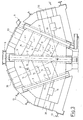
- Another advantage of the invention is that it can be used for any shape of tub, so that, for example in a furnace repair, without changing the floor plan and without any significant change in the existing tub anchorage, the flat ceiling can be applied.
- upright beams can be arranged between the log arches as a transportable and independent element as an intermediate support between the log arches.
- Bendable arches of the conventional type have the disadvantage that they have a tendency to migrate under load have upwards, the means according to the invention also have the task of keeping the arches vertically in alignment and at the same time to keep the escape laterally.
- the invention thus makes it possible for the first time to use bendable arches on a decisive scale as a construction element, since they can be manufactured as transport units and thus there is no need to manufacture on the construction site and constant monitoring during the tempering is no longer necessary, but at the same time permanent function is guaranteed.
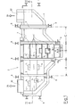
- the inventive design of the blanket 1 consists in that this is formed with the work tub 2 at intervals A, B, C, the load of the ceiling 1 receiving horizontal support elements 3 and the free distances A, B, C between the support elements 3 overlapping, inserted between the support elements 3 horizontal cover plates 4 .
- a load-bearing, flat radiation ceiling can be produced in a comparatively light construction.
- This ceiling system is particularly suitable for the fact that the individual stones used both for the support elements 3 and for the cover plates 4 are designed as modules of a collective or a family of stone building elements, depending on their shape or dimension.
- This construction with components designed or assembled as modules provides, as mentioned previously, the possibility of carrying out the construction as a computer aided design (CAD), which has considerable advantages in terms of design effort, time required for construction and Calculation, as well as reduction of manufacturing costs by using typed or modulated individual elements.
- CAD computer aided design
- the ceiling components 3, 4 joined together to form the ceiling 1 of the work tub 2 in a modular construction form a flat ceiling with a clear vertical distance of the surface 5 of the melt 29 is arranged between 75 mm and 700 mm.
- the support elements 3 are each formed and arranged as perpendicular, straight arches resting on the walls 6 of the basin 7 forming the tub 2.
- cover plates 4 With the inventive design of the radiation ceiling above the work tub, a particularly effective and thus essential design of the cover plates 4 results from the fact that these on the guide areas 13, 13 'of the bends 3 in to the longitudinal Axis of the arches are displaceable in the parallel direction (FIG. 1) and in particular in that cover plates 4 are formed with openings 14 that can be covered.
- these openings 14 can be distributed in large numbers practically over the entire area of the radiation ceiling. They thus give you the opportunity, on the one hand, to set partial temperature drops in the melt through released openings as a result of radiation, to measure state parameters of the melt such as temperature and viscosity with the introduction of suitable measuring instruments, or by introducing known heating or cooling elements to the state of the melt in the run to be able to influence the work tub significantly and in a targeted manner.
- a further advantage results from the fact that stirrers can also be used locally, which contribute to the homogenization of the melt mass by generating a local convection system with bath circulation. Such a stirrer is shown purely by way of example in FIG. 5.
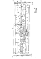
- cover plates 4, as shown in FIG. 2 are displaceably held by mobile holding devices 15.
- a holding device can, for example, as shown purely schematically, have movable tongs which can be moved in a hanging rail track 32 by means of a known lifting device.
- one or the other cover plate 4 can be temporarily removed from its storage and set aside.
- a horizon raised on the lateral furnace frame 10 above the flat ceiling 1 Tal the flat ceiling spanning working and inspection stage 16 is arranged.
- the stage in cooperation with the main features of the flat radiation ceiling and because of the uncomplicated accessibility of the melt surface 5 through the openings 14, is very advantageous and uncomplicated for use with measuring devices 17 for example for measuring the temperature and / or viscosity of the glass melt 18 and of heating or cooling elements 19, stirrers 20 and / or similar means for influencing and / or checking the state parameters of the glass melt.
- measuring devices 17 for example for measuring the temperature and / or viscosity of the glass melt 18 and of heating or cooling elements 19, stirrers 20 and / or similar means for influencing and / or checking the state parameters of the glass melt.
- stirrers 20 stirrers 20 and / or similar means for influencing and / or checking the state parameters of the glass melt.
- the cover plates 4 are preferably made of high-alumina refractory material such as sillimanite. Furthermore, as shown in FIG. 1, these cover plates 4 'are formed with broken, in particular beveled, rounded or chamfered edge regions 26. This successfully avoids the risk of flaking of stone particles in the area of these edges, which could contaminate the molten glass bath.
- the stone elements 23 of the arches 23 made of refractory material with right angles very high silica content like silica material are made.
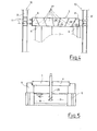
- the invention also consists in the fact that a log sheet 3 made of stones made of refractory material, as has long been known, is not only designed as a transport unit by means of a frame 32, but also avoids the previous disadvantages, while of tempering and during operation require special attention.
- the right-angled arch 3 is held by a frame 32 consisting of a cross member 35 and side webs 36 directed downwards on both sides, which frame 43 can compensate for length extensions during the tempering by means of spring assemblies.
- the springs 43 which can be designed, for example, as plate springs, are arranged in a hollow cylinder 40 and are pretensioned by a pressure plate 42, which is held in position by means of a screw bolt 41.
- the force of the spring assembly 43 acts on a pressure plate 33, which bears against the end faces of the bend 3.
- the expansion of the springs ensures during tempering that both the holding force of the sheet 3 is retained, and on the other hand the expansion but can be included.
- the pressure plates 33 are fixed by means of screw bolts 39 after the tempering, the clearance of which is dimensioned such that they can move freely in the pressing direction, so that they can move freely a T emperaturminderung not hinder the displacement of the pressure plate 33 by the spring packet 43rd
- the clamping screw 47 resting on the side webs 36 presses the bolt 39 against the refractory material of the arch 3 without the other end of the bolt 39 hindering a displacement to maintain the tension of the arch 3.
- the upper cross member 35 has hot eyes 34 and the sheet is held by means of retaining bolts 38 which penetrate holes 37 in refractory material and are held by the lateral webs 36.
- U-shaped profiles 44 are attached to the crossmember, which engage the refractory bricks via insulating chamotte 46. Since they rest on the top of the stones, it is ensured that the stones cannot migrate upwards under pressure. This creates the bendable arch as a controllable, predictable and transportable component that makes it possible to create a cover directly over the surface of the glass melt. By creating openings special cooling z. B. before the feeder, but it can also, as mentioned above, elements for additional heating, temperature measurement, stirring and the like can be used.
Landscapes
- Chemical & Material Sciences (AREA)
- Engineering & Computer Science (AREA)
- Materials Engineering (AREA)
- Organic Chemistry (AREA)
- Glass Melting And Manufacturing (AREA)
- Furnace Housings, Linings, Walls, And Ceilings (AREA)
- Glass Compositions (AREA)
- Filling Or Discharging Of Gas Storage Vessels (AREA)
Applications Claiming Priority (5)
| Application Number | Priority Date | Filing Date | Title |
|---|---|---|---|
| DE3615276 | 1986-05-06 | ||
| DE19863615276 DE3615276A1 (de) | 1986-05-06 | 1986-05-06 | Arbeitswanne eines glasschmelzofens |
| DE3711045 | 1987-04-06 | ||
| DE19873711045 DE3711045A1 (de) | 1986-05-06 | 1987-04-06 | Decke fuer einen glasschmelzofen oder eine arbeitswanne |
| CA000558537A CA1330164C (fr) | 1986-05-06 | 1988-02-05 | Toit de protection de l'aire de travail, de la zone de fusion ou de l'alimentateur de paraison d'un four de fusion du verre |
Publications (3)
| Publication Number | Publication Date |
|---|---|
| EP0244710A2 true EP0244710A2 (fr) | 1987-11-11 |
| EP0244710A3 EP0244710A3 (en) | 1989-08-02 |
| EP0244710B1 EP0244710B1 (fr) | 1992-01-29 |
Family
ID=27167873
Family Applications (1)
| Application Number | Title | Priority Date | Filing Date |
|---|---|---|---|
| EP87106005A Expired - Lifetime EP0244710B1 (fr) | 1986-05-06 | 1987-04-24 | Toit pour un four de fusion de verre ou d'un avant-bassin |
Country Status (6)
| Country | Link |
|---|---|
| US (1) | US4836841A (fr) |
| EP (1) | EP0244710B1 (fr) |
| AT (1) | ATE72211T1 (fr) |
| CA (1) | CA1330164C (fr) |
| DE (3) | DE3615276A1 (fr) |
| ES (1) | ES2029807T3 (fr) |
Families Citing this family (5)
| Publication number | Priority date | Publication date | Assignee | Title |
|---|---|---|---|---|
| US5007950A (en) * | 1989-12-22 | 1991-04-16 | Ppg Industries, Inc. | Compressed, wedged float glass bottom structure |
| US20160238279A1 (en) * | 2015-02-13 | 2016-08-18 | Corning Incorporated | Methods of processing a furnace |
| DK3431447T3 (da) * | 2017-07-21 | 2020-06-02 | Engie | Fremgangsmåde til smeltning af råmaterialer såsom glas ved hjælp af en tvær-fyret smelteovn |
| CN107576200A (zh) * | 2017-09-21 | 2018-01-12 | 贵州航天新力铸锻有限责任公司 | 台车式加热炉的炉底板的放置方法 |
| KR102415723B1 (ko) * | 2017-11-20 | 2022-07-04 | 코닝 인코포레이티드 | 용탕 교반 시스템 및 용탕 교반 방법 |
Family Cites Families (15)
| Publication number | Priority date | Publication date | Assignee | Title |
|---|---|---|---|---|
| US1339615A (en) * | 1916-12-14 | 1920-05-11 | Wundrack Otto | Flat arch for furnaces |
| US1949380A (en) * | 1929-11-05 | 1934-02-27 | Owens Illinois Glass Co | Glass furnace |
| DE639573C (de) * | 1933-11-15 | 1936-12-08 | Josef Watzula | Glasschmelzofen |
| US2773111A (en) * | 1948-01-23 | 1956-12-04 | Saint Gobain | Method and apparatus for manufacturing glass |
| US2834306A (en) * | 1952-02-26 | 1958-05-13 | Pilkington Brothers Ltd | Furnaces |
| DE1015976B (de) * | 1956-02-09 | 1957-09-19 | Bbc Brown Boveri & Cie | Haengedecke fuer Industrieoefen, Kuehlkammern od. dgl. mit grossen Abmessungen |
| DE1130116B (de) * | 1959-06-26 | 1962-05-24 | Georges Henry | Vorrichtung zur Regelung des Betriebes von Glasschmelz-Wannenoefen |
| US3134199A (en) * | 1960-05-19 | 1964-05-26 | North American Refractories | Complexed refractory brick |
| US3248203A (en) * | 1961-10-30 | 1966-04-26 | Owens Corning Fiberglass Corp | Apparatus for heat control of forehearths |
| FR1317242A (fr) * | 1961-11-27 | 1963-02-08 | Glaces De Boussois | Perfectionnements aux installations pour la fabrication du verre plat |
| US3201219A (en) * | 1962-06-01 | 1965-08-17 | Frazier Simplex | Glass melting furnace |
| DE2203944A1 (de) * | 1972-01-28 | 1973-08-02 | Schulte Fa D W | Bauverband feuerfester bausteine fuer haengedecken |
| IT8322362U1 (it) * | 1983-07-14 | 1985-01-14 | S I T I Soc Impianti Termoelettrici Industriali S P A | Strutture di sostegno per volte di Forni |
| US4622059A (en) * | 1985-10-08 | 1986-11-11 | Emhart Industries, Inc. | Apparatus for controlling temperature within a forehearth |
| US4704155A (en) * | 1986-06-11 | 1987-11-03 | Ppg Industries, Inc. | Heating vessel lid construction for a glass melting furnace |
-
1986
- 1986-05-06 DE DE19863615276 patent/DE3615276A1/de active Granted
-
1987
- 1987-04-06 DE DE19873711045 patent/DE3711045A1/de not_active Withdrawn
- 1987-04-24 DE DE8787106005T patent/DE3776397D1/de not_active Expired - Fee Related
- 1987-04-24 AT AT87106005T patent/ATE72211T1/de not_active IP Right Cessation
- 1987-04-24 EP EP87106005A patent/EP0244710B1/fr not_active Expired - Lifetime
- 1987-04-24 ES ES198787106005T patent/ES2029807T3/es not_active Expired - Lifetime
- 1987-04-29 US US07/043,872 patent/US4836841A/en not_active Expired - Lifetime
-
1988
- 1988-02-05 CA CA000558537A patent/CA1330164C/fr not_active Expired - Fee Related
Also Published As
| Publication number | Publication date |
|---|---|
| ES2029807T3 (es) | 1992-10-01 |
| DE3711045A1 (de) | 1988-10-27 |
| US4836841A (en) | 1989-06-06 |
| ATE72211T1 (de) | 1992-02-15 |
| EP0244710B1 (fr) | 1992-01-29 |
| DE3615276A1 (de) | 1987-11-19 |
| CA1330164C (fr) | 1994-06-14 |
| DE3615276C2 (fr) | 1988-03-10 |
| EP0244710A3 (en) | 1989-08-02 |
| DE3776397D1 (de) | 1992-03-12 |
Similar Documents
| Publication | Publication Date | Title |
|---|---|---|
| CH710497A1 (de) | Feuerfeste Wand, insbesondere für einen Verbrennungsofen. | |
| DE1471988A1 (de) | Apparat zum Erwaermen von Glasscheiben | |
| EP3355015B1 (fr) | Élément de support pour un chariot ou une plaque coulissante de four tunnel, chariot ou plaque coulissante de four tunnel dotés des tels éléments de support ainsi que four tunnel doté d'un tel chariot ou d'une telle plaque coulissante de four tunnel | |
| DE3839346C1 (fr) | ||
| EP0244710B1 (fr) | Toit pour un four de fusion de verre ou d'un avant-bassin | |
| EP0378821B1 (fr) | Installation de grille poussante pour le traitement thermique de matières divisées | |
| EP3296476B1 (fr) | Dispositif de liaison d'un mur de bâtiment à une dalle de sol ou de plafond et élément de moulage d'un tel système | |
| DE3739452C1 (de) | Koksofentuer mit keramischem Schildaufbau | |
| EP0019652B1 (fr) | Grille pour un chauffage à lit fluidisé | |
| DE2837580C2 (de) | Gestell zum Zwischenlagern von Brennelement-Bündeln | |
| DE3832358C2 (fr) | ||
| DE3214291A1 (de) | Brandschutzplatte und verfahren zu deren herstellung | |
| DE2540401B2 (de) | Feuerfest in Sandwichbauweise zugestellter Tunnelofen | |
| WO2006079518A1 (fr) | Dispositif pour porter des produits a cuire, presentant une compensation definie de la dilatation thermique | |
| DE2431029A1 (de) | Bodenplatte fuer fertigwohnzellen und verfahren zur montage der wohnzellen | |
| DE2122702A1 (de) | Ofen zur Glasherstellung | |
| DE2324549A1 (de) | Montagestation zur herstellung von raumkaesten | |
| DE2939599A1 (de) | Floatglasanlage mit heizeinrichtungen | |
| DE3721640C1 (en) | Furnace wall or ceiling | |
| DD145301A1 (de) | Gleiteinrichtung fuer verschiebbare arbeits-und lehrgerueste | |
| DE29607059U1 (de) | Stütz- und Führungsgerüst für eine Stranggießanlage | |
| DE4301841C2 (de) | Periodischer Ofen | |
| DE3520615C2 (fr) | ||
| EP0600386A1 (fr) | Four à longerons mobiles | |
| DE2923612A1 (de) | Waermebehandlungsofen |
Legal Events
| Date | Code | Title | Description |
|---|---|---|---|
| PUAI | Public reference made under article 153(3) epc to a published international application that has entered the european phase |
Free format text: ORIGINAL CODE: 0009012 |
|
| AK | Designated contracting states |
Kind code of ref document: A2 Designated state(s): AT BE CH DE ES FR GB IT LI NL SE |
|
| PUAL | Search report despatched |
Free format text: ORIGINAL CODE: 0009013 |
|
| AK | Designated contracting states |
Kind code of ref document: A3 Designated state(s): AT BE CH DE ES FR GB IT LI NL SE |
|
| 17P | Request for examination filed |
Effective date: 19890914 |
|
| RAP1 | Party data changed (applicant data changed or rights of an application transferred) |
Owner name: BETEILIGUNGEN SORG GMBH & CO. KG |
|
| 17Q | First examination report despatched |
Effective date: 19900720 |
|
| RAP1 | Party data changed (applicant data changed or rights of an application transferred) |
Owner name: BETEILIGUNGEN SORG GMBH & CO. KG |
|
| GRAA | (expected) grant |
Free format text: ORIGINAL CODE: 0009210 |
|
| AK | Designated contracting states |
Kind code of ref document: B1 Designated state(s): AT BE CH DE ES FR GB IT LI NL SE |
|
| REF | Corresponds to: |
Ref document number: 72211 Country of ref document: AT Date of ref document: 19920215 Kind code of ref document: T |
|
| ITF | It: translation for a ep patent filed | ||
| ET | Fr: translation filed | ||
| GBT | Gb: translation of ep patent filed (gb section 77(6)(a)/1977) | ||
| REF | Corresponds to: |
Ref document number: 3776397 Country of ref document: DE Date of ref document: 19920312 |
|
| PLBI | Opposition filed |
Free format text: ORIGINAL CODE: 0009260 |
|
| REG | Reference to a national code |
Ref country code: ES Ref legal event code: FG2A Ref document number: 2029807 Country of ref document: ES Kind code of ref document: T3 |
|
| 26 | Opposition filed |
Opponent name: FIRMA HERMANN HEYE Effective date: 19920912 |
|
| NLR1 | Nl: opposition has been filed with the epo |
Opponent name: FIRMA HERMANN HEYE. |
|
| PLBN | Opposition rejected |
Free format text: ORIGINAL CODE: 0009273 |
|
| STAA | Information on the status of an ep patent application or granted ep patent |
Free format text: STATUS: OPPOSITION REJECTED |
|
| 27O | Opposition rejected |
Effective date: 19930321 |
|
| NLR2 | Nl: decision of opposition | ||
| EAL | Se: european patent in force in sweden |
Ref document number: 87106005.9 |
|
| PGFP | Annual fee paid to national office [announced via postgrant information from national office to epo] |
Ref country code: CH Payment date: 19970325 Year of fee payment: 11 |
|
| PGFP | Annual fee paid to national office [announced via postgrant information from national office to epo] |
Ref country code: SE Payment date: 19970327 Year of fee payment: 11 |
|
| PGFP | Annual fee paid to national office [announced via postgrant information from national office to epo] |
Ref country code: BE Payment date: 19980319 Year of fee payment: 12 |
|
| PG25 | Lapsed in a contracting state [announced via postgrant information from national office to epo] |
Ref country code: SE Free format text: LAPSE BECAUSE OF NON-PAYMENT OF DUE FEES Effective date: 19980425 |
|
| PG25 | Lapsed in a contracting state [announced via postgrant information from national office to epo] |
Ref country code: LI Free format text: LAPSE BECAUSE OF NON-PAYMENT OF DUE FEES Effective date: 19980430 Ref country code: CH Free format text: LAPSE BECAUSE OF NON-PAYMENT OF DUE FEES Effective date: 19980430 |
|
| PGFP | Annual fee paid to national office [announced via postgrant information from national office to epo] |
Ref country code: NL Payment date: 19980430 Year of fee payment: 12 |
|
| REG | Reference to a national code |
Ref country code: CH Ref legal event code: PL |
|
| EUG | Se: european patent has lapsed |
Ref document number: 87106005.9 |
|
| PG25 | Lapsed in a contracting state [announced via postgrant information from national office to epo] |
Ref country code: BE Free format text: LAPSE BECAUSE OF NON-PAYMENT OF DUE FEES Effective date: 19990430 |
|
| BERE | Be: lapsed |
Owner name: BETEILIGUNGEN SORG G.M.B.H. & CO. K.G. Effective date: 19990430 |
|
| PG25 | Lapsed in a contracting state [announced via postgrant information from national office to epo] |
Ref country code: NL Free format text: LAPSE BECAUSE OF NON-PAYMENT OF DUE FEES Effective date: 19991101 |
|
| NLV4 | Nl: lapsed or anulled due to non-payment of the annual fee |
Effective date: 19991101 |
|
| PGFP | Annual fee paid to national office [announced via postgrant information from national office to epo] |
Ref country code: FR Payment date: 20000321 Year of fee payment: 14 Ref country code: DE Payment date: 20000321 Year of fee payment: 14 |
|
| PGFP | Annual fee paid to national office [announced via postgrant information from national office to epo] |
Ref country code: ES Payment date: 20000407 Year of fee payment: 14 |
|
| PGFP | Annual fee paid to national office [announced via postgrant information from national office to epo] |
Ref country code: AT Payment date: 20000412 Year of fee payment: 14 |
|
| PGFP | Annual fee paid to national office [announced via postgrant information from national office to epo] |
Ref country code: GB Payment date: 20000419 Year of fee payment: 14 |
|
| PG25 | Lapsed in a contracting state [announced via postgrant information from national office to epo] |
Ref country code: GB Free format text: LAPSE BECAUSE OF NON-PAYMENT OF DUE FEES Effective date: 20010424 Ref country code: AT Free format text: LAPSE BECAUSE OF NON-PAYMENT OF DUE FEES Effective date: 20010424 |
|
| PG25 | Lapsed in a contracting state [announced via postgrant information from national office to epo] |
Ref country code: ES Free format text: LAPSE BECAUSE OF NON-PAYMENT OF DUE FEES Effective date: 20010425 |
|
| PG25 | Lapsed in a contracting state [announced via postgrant information from national office to epo] |
Ref country code: FR Free format text: THE PATENT HAS BEEN ANNULLED BY A DECISION OF A NATIONAL AUTHORITY Effective date: 20010430 |
|
| GBPC | Gb: european patent ceased through non-payment of renewal fee |
Effective date: 20010424 |
|
| PG25 | Lapsed in a contracting state [announced via postgrant information from national office to epo] |
Ref country code: DE Free format text: LAPSE BECAUSE OF NON-PAYMENT OF DUE FEES Effective date: 20020201 |
|
| REG | Reference to a national code |
Ref country code: FR Ref legal event code: ST |
|
| REG | Reference to a national code |
Ref country code: ES Ref legal event code: FD2A Effective date: 20030303 |
|
| PG25 | Lapsed in a contracting state [announced via postgrant information from national office to epo] |
Ref country code: IT Free format text: LAPSE BECAUSE OF NON-PAYMENT OF DUE FEES;WARNING: LAPSES OF ITALIAN PATENTS WITH EFFECTIVE DATE BEFORE 2007 MAY HAVE OCCURRED AT ANY TIME BEFORE 2007. THE CORRECT EFFECTIVE DATE MAY BE DIFFERENT FROM THE ONE RECORDED. Effective date: 20050424 |