EP0244751A2 - Automatisches Analysesystem mit Mehrfachströmen - Google Patents
Automatisches Analysesystem mit Mehrfachströmen Download PDFInfo
- Publication number
- EP0244751A2 EP0244751A2 EP87106219A EP87106219A EP0244751A2 EP 0244751 A2 EP0244751 A2 EP 0244751A2 EP 87106219 A EP87106219 A EP 87106219A EP 87106219 A EP87106219 A EP 87106219A EP 0244751 A2 EP0244751 A2 EP 0244751A2
- Authority
- EP
- European Patent Office
- Prior art keywords
- sample
- computer
- analysis system
- multiport
- multiple stream
- Prior art date
- Legal status (The legal status is an assumption and is not a legal conclusion. Google has not performed a legal analysis and makes no representation as to the accuracy of the status listed.)
- Ceased
Links
- 238000004458 analytical method Methods 0.000 title claims abstract description 55
- 238000000034 method Methods 0.000 claims abstract description 76
- 230000008569 process Effects 0.000 claims abstract description 73
- 239000012530 fluid Substances 0.000 claims abstract description 24
- 230000004044 response Effects 0.000 claims abstract description 7
- 238000005070 sampling Methods 0.000 claims description 16
- 239000002699 waste material Substances 0.000 claims description 15
- 239000000243 solution Substances 0.000 claims description 9
- 238000004891 communication Methods 0.000 claims description 7
- 238000011088 calibration curve Methods 0.000 claims description 4
- 238000002347 injection Methods 0.000 claims description 3
- 239000007924 injection Substances 0.000 claims description 3
- 238000000605 extraction Methods 0.000 claims 1
- 239000000203 mixture Substances 0.000 claims 1
- 239000000470 constituent Substances 0.000 abstract description 9
- 238000004519 manufacturing process Methods 0.000 abstract description 7
- 239000000523 sample Substances 0.000 description 82
- 238000012544 monitoring process Methods 0.000 description 8
- 238000004886 process control Methods 0.000 description 8
- 238000004164 analytical calibration Methods 0.000 description 4
- 238000010276 construction Methods 0.000 description 4
- 238000012864 cross contamination Methods 0.000 description 4
- 230000001276 controlling effect Effects 0.000 description 3
- XKRFYHLGVUSROY-UHFFFAOYSA-N Argon Chemical compound [Ar] XKRFYHLGVUSROY-UHFFFAOYSA-N 0.000 description 2
- XEEYBQQBJWHFJM-UHFFFAOYSA-N Iron Chemical compound [Fe] XEEYBQQBJWHFJM-UHFFFAOYSA-N 0.000 description 2
- PXHVJJICTQNCMI-UHFFFAOYSA-N Nickel Chemical compound [Ni] PXHVJJICTQNCMI-UHFFFAOYSA-N 0.000 description 2
- 229910052770 Uranium Inorganic materials 0.000 description 2
- 238000013459 approach Methods 0.000 description 2
- 238000010586 diagram Methods 0.000 description 2
- 238000012423 maintenance Methods 0.000 description 2
- 238000011027 product recovery Methods 0.000 description 2
- 238000011084 recovery Methods 0.000 description 2
- 239000012087 reference standard solution Substances 0.000 description 2
- 230000008439 repair process Effects 0.000 description 2
- 239000012086 standard solution Substances 0.000 description 2
- 239000000126 substance Substances 0.000 description 2
- JFALSRSLKYAFGM-UHFFFAOYSA-N uranium(0) Chemical compound [U] JFALSRSLKYAFGM-UHFFFAOYSA-N 0.000 description 2
- XLYOFNOQVPJJNP-UHFFFAOYSA-N water Substances O XLYOFNOQVPJJNP-UHFFFAOYSA-N 0.000 description 2
- ZOXJGFHDIHLPTG-UHFFFAOYSA-N Boron Chemical compound [B] ZOXJGFHDIHLPTG-UHFFFAOYSA-N 0.000 description 1
- OYPRJOBELJOOCE-UHFFFAOYSA-N Calcium Chemical compound [Ca] OYPRJOBELJOOCE-UHFFFAOYSA-N 0.000 description 1
- VYZAMTAEIAYCRO-UHFFFAOYSA-N Chromium Chemical compound [Cr] VYZAMTAEIAYCRO-UHFFFAOYSA-N 0.000 description 1
- 229910052688 Gadolinium Inorganic materials 0.000 description 1
- 241000237858 Gastropoda Species 0.000 description 1
- ZOKXTWBITQBERF-UHFFFAOYSA-N Molybdenum Chemical compound [Mo] ZOKXTWBITQBERF-UHFFFAOYSA-N 0.000 description 1
- HCHKCACWOHOZIP-UHFFFAOYSA-N Zinc Chemical compound [Zn] HCHKCACWOHOZIP-UHFFFAOYSA-N 0.000 description 1
- 230000002159 abnormal effect Effects 0.000 description 1
- 239000002253 acid Substances 0.000 description 1
- 230000009471 action Effects 0.000 description 1
- 229910052782 aluminium Inorganic materials 0.000 description 1
- XAGFODPZIPBFFR-UHFFFAOYSA-N aluminium Chemical compound [Al] XAGFODPZIPBFFR-UHFFFAOYSA-N 0.000 description 1
- 229910052786 argon Inorganic materials 0.000 description 1
- 230000009286 beneficial effect Effects 0.000 description 1
- 230000008901 benefit Effects 0.000 description 1
- 235000013361 beverage Nutrition 0.000 description 1
- 230000002457 bidirectional effect Effects 0.000 description 1
- 229910052796 boron Inorganic materials 0.000 description 1
- -1 cadium Chemical compound 0.000 description 1
- 229910052791 calcium Inorganic materials 0.000 description 1
- 239000011575 calcium Substances 0.000 description 1
- 230000015556 catabolic process Effects 0.000 description 1
- 238000006243 chemical reaction Methods 0.000 description 1
- 229910052804 chromium Inorganic materials 0.000 description 1
- 239000011651 chromium Substances 0.000 description 1
- 239000013068 control sample Substances 0.000 description 1
- 238000006731 degradation reaction Methods 0.000 description 1
- 230000003111 delayed effect Effects 0.000 description 1
- 230000000694 effects Effects 0.000 description 1
- 238000011156 evaluation Methods 0.000 description 1
- 239000000446 fuel Substances 0.000 description 1
- UIWYJDYFSGRHKR-UHFFFAOYSA-N gadolinium atom Chemical compound [Gd] UIWYJDYFSGRHKR-UHFFFAOYSA-N 0.000 description 1
- 231100001261 hazardous Toxicity 0.000 description 1
- 239000002920 hazardous waste Substances 0.000 description 1
- 238000009616 inductively coupled plasma Methods 0.000 description 1
- 229910052742 iron Inorganic materials 0.000 description 1
- 239000007788 liquid Substances 0.000 description 1
- 230000007257 malfunction Effects 0.000 description 1
- WPBNNNQJVZRUHP-UHFFFAOYSA-L manganese(2+);methyl n-[[2-(methoxycarbonylcarbamothioylamino)phenyl]carbamothioyl]carbamate;n-[2-(sulfidocarbothioylamino)ethyl]carbamodithioate Chemical compound [Mn+2].[S-]C(=S)NCCNC([S-])=S.COC(=O)NC(=S)NC1=CC=CC=C1NC(=S)NC(=O)OC WPBNNNQJVZRUHP-UHFFFAOYSA-L 0.000 description 1
- 229910052751 metal Inorganic materials 0.000 description 1
- 239000002184 metal Substances 0.000 description 1
- 229910052750 molybdenum Inorganic materials 0.000 description 1
- 239000011733 molybdenum Substances 0.000 description 1
- 229910052759 nickel Inorganic materials 0.000 description 1
- 239000003758 nuclear fuel Substances 0.000 description 1
- 230000003287 optical effect Effects 0.000 description 1
- 239000002245 particle Substances 0.000 description 1
- 238000005504 petroleum refining Methods 0.000 description 1
- 238000010248 power generation Methods 0.000 description 1
- 238000002360 preparation method Methods 0.000 description 1
- 230000002265 prevention Effects 0.000 description 1
- 238000012545 processing Methods 0.000 description 1
- 238000010223 real-time analysis Methods 0.000 description 1
- 230000001105 regulatory effect Effects 0.000 description 1
- 229910052706 scandium Inorganic materials 0.000 description 1
- SIXSYDAISGFNSX-UHFFFAOYSA-N scandium atom Chemical compound [Sc] SIXSYDAISGFNSX-UHFFFAOYSA-N 0.000 description 1
- 230000011664 signaling Effects 0.000 description 1
- 229910052725 zinc Inorganic materials 0.000 description 1
- 239000011701 zinc Substances 0.000 description 1
Images



Classifications
-
- G—PHYSICS
- G01—MEASURING; TESTING
- G01N—INVESTIGATING OR ANALYSING MATERIALS BY DETERMINING THEIR CHEMICAL OR PHYSICAL PROPERTIES
- G01N35/00—Automatic analysis not limited to methods or materials provided for in any single one of groups G01N1/00 - G01N33/00; Handling materials therefor
- G01N35/08—Automatic analysis not limited to methods or materials provided for in any single one of groups G01N1/00 - G01N33/00; Handling materials therefor using a stream of discrete samples flowing along a tube system, e.g. flow injection analysis
-
- G—PHYSICS
- G01—MEASURING; TESTING
- G01N—INVESTIGATING OR ANALYSING MATERIALS BY DETERMINING THEIR CHEMICAL OR PHYSICAL PROPERTIES
- G01N35/00—Automatic analysis not limited to methods or materials provided for in any single one of groups G01N1/00 - G01N33/00; Handling materials therefor
- G01N35/10—Devices for transferring samples or any liquids to, in, or from, the analysis apparatus, e.g. suction devices, injection devices
- G01N35/1095—Devices for transferring samples or any liquids to, in, or from, the analysis apparatus, e.g. suction devices, injection devices for supplying the samples to flow-through analysers
- G01N35/1097—Devices for transferring samples or any liquids to, in, or from, the analysis apparatus, e.g. suction devices, injection devices for supplying the samples to flow-through analysers characterised by the valves
Definitions
- the present invention relates to an analytical system for automatically monitoring process and/or waste streams in an industrial process pursuant to controllably optimizing the operations thereof.
- Analysis of the constituents in an industrial process stream or streams can provide important analytical information regarding the operating condition of the process. Such information can provide the basis for automatically controlling valves, pumps, reactions, etc., pursuant to optimizing the process. Increased output of a higher quality product can thus be achieved.
- analytical information can indicate the existence of constituent concentrations which exceed or fall below nominal limits and serve to initiate appropriate action which in extreme cases may involve a shutdown of the process. The source of a malfunction may be readily identified such that repair is expedited, and thus downtime is minimized. By comparing the analytical data over a period of time, a degradation trend can be identified such that appropriate maintenance procedures can be conveniently scheduled before the problems become serious.
- the analytical data should be as current as possible. Thus, the gathering and evaluation of this data should be performed on a real-time basis for best results. Continuous monitoring of a stream would be ideal; however, typically plural streams or plural points along a single stream need to be monitored. This would indeed be the case if product, waste, recovery and treatment streams are all to be monitored. Continuous monitoring of all of these streams would require an analytical detector devoted to each monitoring point. In many process applications, it is necessary to monitor the various streams for not only the presence of a plurality of elements, but also the concentrations of each. A single analytical device capable of analyzing for all of the elements of interest or a separate device for each element duplicated at each monitoring point makes continuous real-time monitoring a very costly approach.
- An additional object is to provide a system of the above-character wherein analytical data pertaining to the concentrations of plural constituents is developed rapidly on a real-time basis.
- a further object is to provide a system of the above-character wherein samplings from a plurality of streams are taken for analysis in accordance with a predetermined schedule.
- Yet another object of the present invention to provide a system of the above-character wherein a sampling schedule may be interrupted on demand to take a sample from any selected stream for analysis.
- An additional object is to provide a system of the above-character wherein cross-contamination between consecutive samples is avoided.
- a further object is to provide a system of the above character wherein standardization of the analytical device or devices is performed automatically.
- Yet another object is to provide a system of the above character wherein the integrity of each sample is preserved.
- Another object is to provide a system of the above-character wherein the analytical data is utilized to control a process or processes involving the various streams.
- an automated, on-line system for analyzing the concentrations of plural constituents in a plurality of process streams.
- the resulting analytical data is processed and utilized for process control, signalling abnormal operating conditions, and reporting results.
- the various process streams to be monitored are each equipped with a sampling loop through which a shunted portion of the fluid stream continuously flows. These sample loops are piped through different ports of a multiport valve included in a sample selection subsystem whose operation is normally automated by a computer pursuant to a predetermined sample selection schedule.
- This sample selection computer controllably operates the multiport valve to extract a sample from a selected stream which is routed to an analytical instrument for chemical analysis.
- Analytical data pertaining to the analysis results is compared with an appropriate analytical control table in the sample selection computer to identify any off-limits constituent concentrations.
- the multiport valve is also computer controlled to inject rinse solutions for sample cross-contamination prevention and to inject standard solution for analytical instrument calibration.
- the sample selection computer also accepts requests from an operator and from a process control computer to take a sample from any selected stream. Provision is also made to take a sample from a manually collected specimen for analysis.
- each subsystem is assigned primary responsibility for different groups of process streams, however both subsystems have the capability to sample all process streams for complete redundancy.
- the ability to timely provide analytical data necessary for process control is not jeopardized while one of the subsystems is occupied with running an instrument calibration routine or is down for maintenance and repair.
- the computer controlling the process responsible for the various process streams communicates with the host computer and directly with the sample selection computers, and thus real-time process control is not jeopardized should the host computer go down.
- reference numeral 10 generally refers to an industrial process for producing a desired product.
- process 10 may represent several related processes such as a product producing process, together with a product recovery process and a waste treatment process concerned with effluents from the product process.
- Involved with process or processes 10 are a plurality of process streams 10a-10g consisting of fluids following in pipes, conduits, reactors, etc.
- Controlling the multiplicity of valves, pumps, etc. involved in process 10 is a process computer 12 via a multitude of signal paths commonly indicated at 14. Signals are also transmitted back to the process computer to provide information as to a variety of conditions existing in the process, such as temperature, pressure, flow rates, etc., as well as feedback signals indicating that the computer commands are indeed being executed.
- an automated multiple stream analysis system Connected in communication with process computer 10 via data links 16 and 18 is an automated multiple stream analysis system, generally indicated at 20.
- This system is seen to include a host computer 22 and a pair of identically configured sample selection subsystems generally indicated at 23A and 23B.
- Each of these subsystems includes a computer 24, a plurality of multiport valves commonly indicated at 26, an analytical instrument, such as an inductively coupled plasma spectrometer 28, and its associated computer 30.
- sample loops 32a through 32g are connected to shunt representative portions of the fluids flowing in streams 10a through 10g, respectively, to multiport valves 26 of sample selection subsystem 23A, while sample loops 34a through 34g shunt representative portions of the fluids flowing in streams 10a through 10g, respectively, to multiport valves 26 of subsystem 23B.
- the multiport valves of both subsystems 23A and 23B are capable of taking samples from all of the process streams 10a through 10g for full redundancy, however normally the sampling load is shared between the two subsystems under the control of host computer 22. This insures that all process streams can be monitored even though one of the subsystems is down for servicing or occupied in an instrument calibration routine.
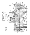
- each multiport valve 26 is constructed having a manifold block 36, a valve block 38, a rotor 40, and an indexer or stepping motor 42.
- the valve block is secured to the manifold block by a circular array of bolts 44 extending through clearance bores 44a in the valve block and threaded into tapped bores 44b in the manifold block.
- the manifold block is formed with a plurality of angularly spaced pairs of radially aligned passages 36a and 36b (FIGURE 4) which are countersunk at their illustrated lower ends to receive the ends of a pair of metal tubes 46a and 46b, respectively.
- Each manifold passage pair 36a and 36b which respectively constitute valve inlet and outlet ports, communicates with a separate pair of valve block passages 38a and 38b, respectively, which are in communication at their upper ends with a cross passage 38c.
- Each of these latter passages is extended to present a circular array of angularly spaced outlet ends 38d in selective communication with the radially outer open end of a single inverted U-shaped passage 40a formed in rotor 40.
- the inner leg of this U-shaped passage is aligned with the rotor axis with its open lower end communicating with a centrally located valve block passage 38e via a union 48.
- This union also serves to mount rotor 40 to valve block 38 for bidirectional rotation by indexer 42 connected to the rotor via a rotor shaft 40b.
- the single, common central valve block passage 38a communicates with a single, common manifold block passage 36c (FIGURE 4), whose lower end is countersunk to receive the end of a common outlet tube 50.
- Passage 36c constitutes the common outlet port of valve 26.
- Suitable seals such as the illustrated O-ring seals, prevent fluid leakage at the interfaces of the manifold block, valve block, and rotor.
- each of the pairs of tubes 46a, 46b, manifold block passages 36a, 36b, and valve block passages 38a, 38b and 38c constitute one of the sample loops 32a-32g, 34a-34g.
- the continuous fluid flow through a sample loop of a stream which is not being sampled is illustrated by the arrows 52 in FIGURE 3.
- rotor 40 By positioning rotor 40 to communicate its passage 40a with a selected one of the valve block passage outlets 38d as commanded by the associated sample selection subsystem computer 24 over data link 54, fluid flow in the selected sample loop is diverted to the path indicated by arrows 56. A sample is thus taken from the selected stream 10a-10g and directed by outlet tube 50 to spectrometer 28 for analysis.
- the multiport valves accommodate continuous flow of fluid through the sample loops connected thereto, and thus a sample extracted from a selected sample loop is truely representive on a real-time basis of the fluid flowing in the associated process stream. In other words, none of the sample loops contains any dead fluid volume which would pertain to fluid flowing in a process stream at some time in the past.
- the above described multiport valve construction facilitates servicing and replacement. That is, should a multiport valve fail, the operating parts thereof can be replaced without disturbing the sample loop connections by simply removing bolts 44 and replacing the valve body-rotor-indexer subassembly as a unit Downtime is thus minimized.
- valve outlet tubes 46b are connected back into the appropriate process stream, however in some cases they may simply be connected to waste.
- each sample selection subsystem 23A, 23B includes at least three multiport valves, indicated at 26a, 26b and 26c, which are all of the construction illustrated in FIGURE 3. In some applications, such as those involving a large number of sample loops, more than three multiport valves would be implemented.
- Each multiport valve 26a, 26b, 26c responds to positioning commands selectively transmitted thereto over separate communication links 54a, 54b, 54c, respectively, by computer 24.
- Each multiport valve sends back valve position data over these links to verify that it has correctly responded to a computer command and to enable computer 24 to determine which direction the valve rotor should be rotated to reach the next selected valve position over the shortest path.
- valve 26c can readily accommodate sample inputs from more than the illustrated two multiport valves.
- the common outlet of multiport valve 26c is connected via tube 50 to a pump 58 which meters out a predetermined quantity of an extracted sample for injection into spectrometer 28.
- a pump 58 which meters out a predetermined quantity of an extracted sample for injection into spectrometer 28.
- An internal reference standard solution metered out from a source 60 by a pump 62.
- the operations of pumps 58 and 62 are controlled by the instrument computer 30 seen in FIGURE 2.
- the internal reference standard solution contains a predetermined concentration of a unique element which is not present in any of the process streams.
- one or more reservoirs 64 of a rinse solution are connected via tubes 64a to an inlet port 36a (FIGURE 3) of each such valve of each sample selection subsystem 23A, 23B.
- the rinse solutions may consist of pure water and possibly an appropriate acid which are held in separate reservoirs 64 separately piped to different multiport valve inlet ports.
- the sample selection subsystem computers 24 would be programmed to schedule a rinse cycle immediately preceding and immediately following the taking of a sample for analysis by positioning valves 26a, 26b, 26c accordingly.
- these valves may be computer controlled to inject a water plug between extracted samples; these measures being taken to guard against cross-contamination of samples.
- Also connected to separate multiport inlets of both sample selection subsystems by individual tubes commonly indicated at 66a in FIGURE 1 are plurality of containers commonly indicated at 66. Each of these containers holds a different solution containing a known concentration of each element the various samples are to be analyzed for.
- the multiport valves 26a, 26b, 26c of a selected sample selection subsystem are controlled by computer 24 to draw slugs of the various standards containers 66 which are routed successively to spectrometer 28 and the responses thereto are evaluated.
- Computers 24 and 28 work in concert via interconnecting data link 31 to establish separate calibration curves for each spectrometer response to the known element concentration in each standards solution feed to computer 30 over signal link 29.
- computer 30 automatically makes appropriate adjustments to spectrometer to insure that the responses to each standards element is being properly recognized. In this manner, spectrometer 28 and computer 30 are effectively calibrated such as to provide analytical data specifically indicative of the concentrations of those elements or constituents of interest contained in each analyzed sample.
- the sample loops may include two-way valves 68 which are manually operated to interrupt fluid flow therethrough and connect a portion of the loop to a source 69 of air under pressure. In this way, blockages can be blownout with minimal interruption in service. Ideally, this blowout capacity is applied to all of the inlet and outlet ports of each multiport valve.
- solenoid valves 70 are connected in line with tubes 46b communicating with the valve outlet ports. Specifically, these valves are incorporated in those of the valve outlet ports whose associated inlet ports are in communication with the various standards containers 66 via tubes 66a and the rinse reservoirs 64 via tubes 64a.
- valves 26a, 26b and their common outlet ports to multiport valve 26c via tubes 50 are included in the valve outlet tubes 46b.
- flow switches 72 which serve to signal computers 24 that fluid flow in the sample loops is adequate for the taking of a sample and that an extracted sample has reached valve 26c and thus is available for analysis.
- process sensors generally indicated at 73 in FIGURE 1 which further include sensors monitoring ongoing conditions within process 10, fluid levels within the standard containers 66 and rinse reservoirs 64, etc.
- sample injection into the spectrometer is delayed for a sufficient equilibrium time after a flow switch signals adequate flow for the drawn sample to insure a representative sample and to further minimize any sampling cross-contamination.
- flow switches further serve to indicate to computers 24 the existence of any blockages or restrictions to fluid flow.
- an electrically actuated three-way valve 74 remotely controlled by computer 24 is connected into the outlet tube 50 going from the common outlet port of multiport valve 26c to metering pump 58 to draw a sample from a specimen collected manually from a point in the process other than the monitored process streams 10a-10g.
- valve 74 is positioned to draw a sample from a liquid specimen collected in a beaker 75. Analysis of this sample is performed in the same manner as the automatically drawn samples.
- the analysis system 20 of FIGURE 1 has a number of operating modes which are initiated by operator at host computer 22 via its terminal 22a.
- operating parameters for the sample selection subsystem computers 24 and the ICPS computers 30 are established. This includes setting up an analytical control table for each process stream 10a-10g to be sampled. These tables establish what the sample analysis for the various streams should be when the process is operating normally.
- Various levels of alarm limits are also established against which the various element concentrations indicated in each sample analysis are measured. Depending upon which limits the concentration of a particular element in a sample exceed, this fact is displayed at one of the sample selection subsystem computer terminals 24a and/or the host computer terminal 22a, printed out by the host computer printer 22b, and/or alarmed at the process computer terminal 12a.
- Sampling schedules are also entered into the sample selection subsystem computers 24 to set up the frequency at which the various process streams are to be sampled on a continuous basis, which may be on a time basis, e.g. once an hour, or on a sample count basis, e.g. once every twenty samples. Some process streams may be sampled on a demand basis rather than a continuous or automated basis. Sampling of a process stream which is included in the sampling schedule may be requested by an operator from any of the computer terminals 12a, 22a, and 24a, and a sample will be taken from the selected stream and analyzed out of order. The various process streams are prioritized and arranged in a sampling queue accordingly. Requests entered by an operator or generated automatically by the process computer 12 to sample a selected stream are given the highest priority.
- the analytical data pertaining to all of the sample analyses are stored in the host computer for subsequent use in generating various reports and trend information such as selected element concentrations in a specified process stream as indicated by successive sample analyses taken over a specified period of time. Data on past sample analyses for any selected process stream or streams as may be retrieved and display or printed out on operator command.
- Host computer 22 coordinates the operations of sample selection subsystems 23A and 23B in order that the sampling load can be expeditiously shared between them.
- the subsystem computers 24 are programmed to go into a backup mode should the host computer go down, such that sampling and reporting to the process computer 12 can continue on a less flexible operating basis.
- Either one of the sample selection subsystem computers may be put into a standardization mode during which standard samples are drawn from the various containers 66 and injected into spectrometer 28 pursuant to establishing calibration curves for all of the elements of interest.
- Each sample selection subsystem is capable of being put into a diagnostic mode during which an operator can manually troubleshoot the subsystem to determine if it is operating properly.
- either subsystem can be put into a single sample mode wherein an operator may request an analysis of any selected process stream.
- the backup mode capability wherein the subsystems can carry on sample analysis during periods when host computer 22 is inoperative.
- the subsystems perform sample analyses in totally operator-unattended fashion based on the formats established during the setup mode.
- sample analyses There are basically three classes of sample analyses, namely continuous or automated analyses, process control sample analysis requests, and operator sample analysis requests.
- Process control requests are those initiated automatically by the process computer 12 or manually via its terminal 12a to analyze a sample drawn from a specified process stream.
- Operator request are those initiated at either of the computer terminals 22a and 24a to analyze a sample from a specified process stream or from a manually collected sample in beaker 75 (FIGURE 2).
- An operator may also request that a specified standard sample be drawn to verify instrument calibration.
- These operator requests are of the highest priority and can be made at any time. Such requested samples are analyzed immediately upon completion of any analysis in progress.
- the two subsystems are both operating in their automated sampling mode as coordinated by host computer 22. However, at times one subsystem may be in a different mode, such as the diagnostics mode or the standardization mode. The other subsystem can continue in the automated sampling mode to generate the analytical data necessary to support process computer 12 in its process control capacity.
- the automated multiple stream analysis system of the present invention may be applied to a wide variety of diverse process applications involving petroleum refining, petrochemical production, food and beverage processing, power generation, etc.
- the analytical instrumentation may include visible, ultraviolet, infrared, X-ray and mass spectrometers; spectrophotometers; the various types of chromatographs; titrameters, densimeters; and so forth, as well as combinations thereof.
- An application for which the present invention is particularly suited is the fully automated process control of a nuclear fuel manufacturing facility including not only the fuel manufacturing process, but also the processes of recovering uranium from waste streams and waste stream treatment to reduce hazardous waste disposal costs.
- An analytical instrument highly suitable for this application is a Jarrell-Ash 9000 spectrometer, which is a multi-channel, direct-reading, optical emission spectrometer using an argon plasma to excite ionic and atomic particles.
- This instrument under the control of its ICPS computer can simultaneously analyze a sample for the concentrations of a multiplicity of elements of interest, such as uranium, boron, cadium, gadolinium, aluminum, calcium, chromium, iron, manganese, nickel, zinc and molybdenum, as well as an internal reference standard element such as scandium.
- Intel 80/24 microcomputers can be utilized as the sample selection subsystem computers, while the host computer may be a Digital Equipment Corporation 11/24 minicomputer.
- a typical sample analysis time may range from five to seven minutes which includes sample preparation, analysis and analytical data reporting.
Landscapes
- General Health & Medical Sciences (AREA)
- General Physics & Mathematics (AREA)
- Life Sciences & Earth Sciences (AREA)
- Chemical & Material Sciences (AREA)
- Analytical Chemistry (AREA)
- Biochemistry (AREA)
- Immunology (AREA)
- Physics & Mathematics (AREA)
- Health & Medical Sciences (AREA)
- Pathology (AREA)
- Automatic Analysis And Handling Materials Therefor (AREA)
- Sampling And Sample Adjustment (AREA)
- Feedback Control In General (AREA)
- Investigating Or Analysing Materials By Optical Means (AREA)
Applications Claiming Priority (2)
| Application Number | Priority Date | Filing Date | Title |
|---|---|---|---|
| US06/859,544 US4722830A (en) | 1986-05-05 | 1986-05-05 | Automated multiple stream analysis system |
| US859544 | 1986-05-05 |
Publications (2)
| Publication Number | Publication Date |
|---|---|
| EP0244751A2 true EP0244751A2 (de) | 1987-11-11 |
| EP0244751A3 EP0244751A3 (de) | 1989-10-04 |
Family
ID=25331173
Family Applications (1)
| Application Number | Title | Priority Date | Filing Date |
|---|---|---|---|
| EP87106219A Ceased EP0244751A3 (de) | 1986-05-05 | 1987-04-29 | Automatisches Analysesystem mit Mehrfachströmen |
Country Status (3)
| Country | Link |
|---|---|
| US (1) | US4722830A (de) |
| EP (1) | EP0244751A3 (de) |
| JP (1) | JPS62278425A (de) |
Cited By (11)
| Publication number | Priority date | Publication date | Assignee | Title |
|---|---|---|---|---|
| WO1990000250A1 (en) * | 1988-06-29 | 1990-01-11 | The University Of Manchester Institute Of Science And Technology | Method and apparatus for sampling |
| RU2115127C1 (ru) * | 1996-09-30 | 1998-07-10 | Акционерное общество открытого типа "Акционерная компания по транспорту нефти" | Способ определения изменения качества нефти при транспортировке в трубопроводе и система для его осуществления |
| WO1999002961A1 (de) * | 1997-07-10 | 1999-01-21 | Forschungszentrum Jülich GmbH | Verfahren und vorrichtung zur serienprobenahme |
| DE19758356A1 (de) * | 1997-12-22 | 1999-07-08 | Ufz Leipzighalle Gmbh | Modulares Vielkanalprobenahme- und Meßsystem zur automatischen Langzeitanalyse von Fluiden für hydrogeologische Feld- und Laborversuche |
| RU2173452C1 (ru) * | 2000-12-25 | 2001-09-10 | ЗАО "Уралавтоматика инжиниринг" | Система аналитического контроля жидких проб |
| DE10322942A1 (de) * | 2003-05-19 | 2004-12-09 | Hans-Knöll-Institut für Naturstoff-Forschung e.V. | Vorrichtung zum Positionieren und Ausschleusen von in Separationsmedium eingebetteten Fluidkompartimenten |
| DE10322893A1 (de) * | 2003-05-19 | 2004-12-16 | Hans-Knöll-Institut für Naturstoff-Forschung e.V. | Vorrichtung und Verfahren zum Zudosieren von Reaktionsflüssigkeiten zu in Separationsmedium eingebetteten Flüssigkeitskompartimenten |
| WO2010139359A1 (en) | 2009-06-03 | 2010-12-09 | Agilent Technologies, Inc. | Sample injector with metering device balancing pressure differences in an intermediate valve state |
| RU2419776C2 (ru) * | 2009-05-18 | 2011-05-27 | Закрытое акционерное общество "ТЕХНОЛИНК" | Автоматическая система аналитического контроля жидких проб |
| US10386342B2 (en) | 2008-01-25 | 2019-08-20 | Dionex Softron Gmbh | Sample injector for liquid chromatography, particularly for high performance liquid chromatography |
| US10473631B2 (en) | 2015-06-25 | 2019-11-12 | Dionex Softron Gmbh | Sampler for liquid chromatography |
Families Citing this family (71)
| Publication number | Priority date | Publication date | Assignee | Title |
|---|---|---|---|---|
| US4949252A (en) * | 1985-10-17 | 1990-08-14 | Technology 80, Inc. | Computer channel analyzer with monitoring and selective display of predetermining events and related data |
| US5073499A (en) * | 1988-04-15 | 1991-12-17 | Westinghouse Electric Corp. | Chemical diagnostic system |
| US4957009A (en) * | 1988-09-23 | 1990-09-18 | Spectra-Physics, Inc. | Pushloop liquid sampling method |
| US5066600A (en) * | 1989-05-19 | 1991-11-19 | Cummins Engine Company, Inc. | Multiple waste isolation system |
| DE4014602A1 (de) * | 1990-05-07 | 1991-11-14 | Max Planck Gesellschaft | Dosiervorrichtung mit radialer anordnung von ventilen |
| US5246668A (en) * | 1990-09-20 | 1993-09-21 | Space Biospheres Ventures | Air sampling and analysis system |
| US5268300A (en) * | 1991-07-08 | 1993-12-07 | Nalco Chemical Company | Auditing contaminated water effluents for feasible reuse |
| US5387395A (en) * | 1992-07-06 | 1995-02-07 | Beckman Instruments, Inc. | Fluid distribution manifold |
| US5419208A (en) * | 1993-01-29 | 1995-05-30 | Upchurch Scientific, Inc. | Multiport selection valve |
| US5902551A (en) * | 1995-01-13 | 1999-05-11 | Semi-Gas Systems, Inc. | Process gas docking station with point-of-use filter for receiving removable purifier cartridges |
| CA2146177C (en) * | 1995-04-03 | 2000-09-05 | Adrian P. Wade | Intelligent flow analysis network |
| DE19738566C2 (de) * | 1997-09-04 | 1999-07-29 | Karlsruhe Forschzent | Verfahren und Vorrichtung zur Identifizierung von Wirkstoffen |
| US6267143B1 (en) | 1999-06-29 | 2001-07-31 | Upchurch Scientific, Inc. | Selection valve with ferrule cluster |
| US8518704B2 (en) * | 1999-08-03 | 2013-08-27 | Advanced Micro Devices, Inc. | System and method for monitoring and/or controlling attributes of multiple chemical mixtures with a single sensor |
| US7198753B1 (en) | 1999-08-03 | 2007-04-03 | Advanced Micro Devices, Inc. | System and method for monitoring and/or controlling attributes of multiple chemical mixtures with a single sensor |
| WO2002103202A1 (fr) * | 2001-06-16 | 2002-12-27 | Musashi Engineering, Inc. | Dispositif servant a delivrer une quantite fixe de liquide |
| DE10236160B4 (de) * | 2002-08-07 | 2004-12-02 | Dr.Ing.H.C. F. Porsche Ag | Vorrichtung zur selektiven Zuleitung von Medien, insbesondere bei Emissionsmessungen von Abgasen in Brennkraftmaschinen |
| DE10249771A1 (de) * | 2002-10-24 | 2004-05-13 | AMTEC-Anwendungszentrum für Mikrotechnologien Chemnitz GmbH | Verfahren und Vorrichtung zur Entnahme von flüssigen Proben aus einem oder mehreren Druckbehältern |
| US7162971B2 (en) * | 2002-12-19 | 2007-01-16 | Lattec I/S | Milk conveyer device |
| WO2004057305A2 (en) * | 2002-12-19 | 2004-07-08 | Lattec I/S | A milk conveyer device |
| DE10301421A1 (de) * | 2003-01-16 | 2004-07-29 | Bayer Ag | Prozessanalysensysteme mit automatischer Flüssigprobenvorbereitung und Anbindung zu Prozessleitsystemen |
| US7692219B1 (en) | 2004-06-25 | 2010-04-06 | University Of Hawaii | Ultrasensitive biosensors |
| US7785785B2 (en) | 2004-11-12 | 2010-08-31 | The Board Of Trustees Of The Leland Stanford Junior University | Charge perturbation detection system for DNA and other molecules |
| US7460917B1 (en) | 2005-09-30 | 2008-12-02 | Rockwell Automation Technologies, Inc. | System and method for identifying manufacturing data deviations |
| US11339430B2 (en) | 2007-07-10 | 2022-05-24 | Life Technologies Corporation | Methods and apparatus for measuring analytes using large scale FET arrays |
| US8262900B2 (en) | 2006-12-14 | 2012-09-11 | Life Technologies Corporation | Methods and apparatus for measuring analytes using large scale FET arrays |
| US8349167B2 (en) | 2006-12-14 | 2013-01-08 | Life Technologies Corporation | Methods and apparatus for detecting molecular interactions using FET arrays |
| GB2457851B (en) * | 2006-12-14 | 2011-01-05 | Ion Torrent Systems Inc | Methods and apparatus for measuring analytes using large scale fet arrays |
| EP2307577B1 (de) | 2008-06-25 | 2015-06-03 | Life Technologies Corporation | Verfahren zur analytmessung mithilfe grosser fet-arrays |
| US11951474B2 (en) | 2008-10-22 | 2024-04-09 | Life Technologies Corporation | Fluidics systems for sequential delivery of reagents |
| US20100301398A1 (en) | 2009-05-29 | 2010-12-02 | Ion Torrent Systems Incorporated | Methods and apparatus for measuring analytes |
| US8546128B2 (en) * | 2008-10-22 | 2013-10-01 | Life Technologies Corporation | Fluidics system for sequential delivery of reagents |
| US20100137143A1 (en) * | 2008-10-22 | 2010-06-03 | Ion Torrent Systems Incorporated | Methods and apparatus for measuring analytes |
| US8574835B2 (en) * | 2009-05-29 | 2013-11-05 | Life Technologies Corporation | Scaffolded nucleic acid polymer particles and methods of making and using |
| US8776573B2 (en) | 2009-05-29 | 2014-07-15 | Life Technologies Corporation | Methods and apparatus for measuring analytes |
| US20120261274A1 (en) | 2009-05-29 | 2012-10-18 | Life Technologies Corporation | Methods and apparatus for measuring analytes |
| CH701526B1 (de) * | 2009-07-24 | 2013-02-15 | Camag | Verfahren und Vorrichtung zur Vorbereitung von Substanzen für qualitative und quantitative Analysen. |
| TWI465716B (zh) | 2010-06-30 | 2014-12-21 | 生命技術公司 | 用於檢測及測量化學反應及化合物之電晶體電路 |
| EP2588850B1 (de) | 2010-06-30 | 2016-12-28 | Life Technologies Corporation | Trockentestverfahren für isfet-arrays |
| EP2588851B1 (de) | 2010-06-30 | 2016-12-21 | Life Technologies Corporation | Ion-sensing charge-accumulation circuit and method |
| US11307166B2 (en) | 2010-07-01 | 2022-04-19 | Life Technologies Corporation | Column ADC |
| US8653567B2 (en) | 2010-07-03 | 2014-02-18 | Life Technologies Corporation | Chemically sensitive sensor with lightly doped drains |
| WO2012036679A1 (en) | 2010-09-15 | 2012-03-22 | Life Technologies Corporation | Methods and apparatus for measuring analytes |
| US8685324B2 (en) | 2010-09-24 | 2014-04-01 | Life Technologies Corporation | Matched pair transistor circuits |
| US9970984B2 (en) | 2011-12-01 | 2018-05-15 | Life Technologies Corporation | Method and apparatus for identifying defects in a chemical sensor array |
| US8821798B2 (en) | 2012-01-19 | 2014-09-02 | Life Technologies Corporation | Titanium nitride as sensing layer for microwell structure |
| US8747748B2 (en) | 2012-01-19 | 2014-06-10 | Life Technologies Corporation | Chemical sensor with conductive cup-shaped sensor surface |
| US8786331B2 (en) | 2012-05-29 | 2014-07-22 | Life Technologies Corporation | System for reducing noise in a chemical sensor array |
| US9080968B2 (en) | 2013-01-04 | 2015-07-14 | Life Technologies Corporation | Methods and systems for point of use removal of sacrificial material |
| US9841398B2 (en) | 2013-01-08 | 2017-12-12 | Life Technologies Corporation | Methods for manufacturing well structures for low-noise chemical sensors |
| US8962366B2 (en) | 2013-01-28 | 2015-02-24 | Life Technologies Corporation | Self-aligned well structures for low-noise chemical sensors |
| US8963216B2 (en) | 2013-03-13 | 2015-02-24 | Life Technologies Corporation | Chemical sensor with sidewall spacer sensor surface |
| US8841217B1 (en) | 2013-03-13 | 2014-09-23 | Life Technologies Corporation | Chemical sensor with protruded sensor surface |
| US9116117B2 (en) | 2013-03-15 | 2015-08-25 | Life Technologies Corporation | Chemical sensor with sidewall sensor surface |
| EP2972279B1 (de) | 2013-03-15 | 2021-10-06 | Life Technologies Corporation | Chemischer sensor mit stetigen sensoroberflächen |
| WO2014149779A1 (en) | 2013-03-15 | 2014-09-25 | Life Technologies Corporation | Chemical device with thin conductive element |
| CN105264366B (zh) | 2013-03-15 | 2019-04-16 | 生命科技公司 | 具有一致传感器表面区域的化学传感器 |
| US9835585B2 (en) | 2013-03-15 | 2017-12-05 | Life Technologies Corporation | Chemical sensor with protruded sensor surface |
| US20140336063A1 (en) | 2013-05-09 | 2014-11-13 | Life Technologies Corporation | Windowed Sequencing |
| US10458942B2 (en) | 2013-06-10 | 2019-10-29 | Life Technologies Corporation | Chemical sensor array having multiple sensors per well |
| JP6163213B2 (ja) * | 2013-11-28 | 2017-07-12 | 株式会社日立製作所 | 分析用試料の前処理装置及びそれを用いた分析システム |
| KR102593647B1 (ko) | 2014-12-18 | 2023-10-26 | 라이프 테크놀로지스 코포레이션 | 트랜스미터 구성을 갖춘 높은 데이터율 집적 회로 |
| WO2016100521A1 (en) | 2014-12-18 | 2016-06-23 | Life Technologies Corporation | Methods and apparatus for measuring analytes using large scale fet arrays |
| US10077472B2 (en) | 2014-12-18 | 2018-09-18 | Life Technologies Corporation | High data rate integrated circuit with power management |
| US11371968B2 (en) | 2016-05-30 | 2022-06-28 | Agilent Technologies, Inc. | Branching off fluidic sample with low influence on source flow path |
| EP3252463B1 (de) | 2016-05-30 | 2019-02-20 | Agilent Technologies, Inc. (A Delaware Corporation) | Abzweigung einer fluidprobe mit geringem einfluss auf einen quellströmungsweg |
| US10520477B2 (en) | 2016-12-09 | 2019-12-31 | Idex Health & Science Llc | High pressure valve with multi-piece stator assembly |
| US10384151B2 (en) | 2016-12-09 | 2019-08-20 | Idex Health & Science Llc | High pressure valve with two-piece stator assembly |
| US11054054B2 (en) | 2016-12-09 | 2021-07-06 | Idex Health & Science Llc | High pressure valve with multi-piece stator assembly |
| EP3561504B1 (de) | 2018-04-25 | 2023-01-04 | Idex Health & Science LLC | Hochdruckventil mit mehrteiliger statoranordnung |
| US11953104B2 (en) * | 2021-01-29 | 2024-04-09 | Pathway Industries, Inc. | Rotary multi-way distributor with plural port tracks |
Family Cites Families (17)
| Publication number | Priority date | Publication date | Assignee | Title |
|---|---|---|---|---|
| US3116642A (en) * | 1961-02-28 | 1964-01-07 | Atlas Chem Ind | Fluid sampling device |
| US3674672A (en) * | 1970-03-25 | 1972-07-04 | Hooker Chemical Corp | Multiparameter process solution analyzer-controller |
| US3658478A (en) * | 1970-04-07 | 1972-04-25 | Instrumentation Labor Inc | Fluid analyzing apparatus |
| US3690833A (en) * | 1970-05-04 | 1972-09-12 | Damon Corp | Automated fluids analyzer having selectively interrupted flow |
| FR2245249A5 (de) * | 1973-09-25 | 1975-04-18 | Erap Elf Entr Rech Activ Petro | |
| US4229971A (en) * | 1975-04-28 | 1980-10-28 | Phillips Petroleum Company | Liquid sampling system |
| US4127111A (en) * | 1976-10-26 | 1978-11-28 | Drolet Roland A | Automatic blood sampling system and method |
| JPS5816687B2 (ja) * | 1978-04-24 | 1983-04-01 | 日本電子株式会社 | 試料計量採取装置 |
| US4207465A (en) * | 1978-07-03 | 1980-06-10 | Phillips Petroleum Company | Isotope analysis with a mass spectrometer using small samples |
| JPS55136958A (en) * | 1979-04-14 | 1980-10-25 | Olympus Optical Co Ltd | Automatic analyzer |
| JPS56114763A (en) * | 1980-02-15 | 1981-09-09 | Jeol Ltd | Automatic chemical analyzer |
| JPS5936432B2 (ja) * | 1980-08-25 | 1984-09-04 | 株式会社東芝 | 半導体装置の製造方法 |
| US4472354A (en) * | 1980-10-21 | 1984-09-18 | Electric Power Research Institute, Inc. | System for continuously monitoring the ionic content of steam-producing water |
| US4424559A (en) * | 1981-02-27 | 1984-01-03 | New Brunswick Scientific Co., Inc. | Modular instrumentation for monitoring and control of biochemical processes |
| US4361538A (en) * | 1981-03-17 | 1982-11-30 | Davy International Ag | Continuous moving bed reactor for manufacture of high molecular weight polyethylene terephthalate |
| JPS589072A (ja) * | 1981-07-10 | 1983-01-19 | Seishin Seiyaku Kk | オ−トサンプラ− |
| JPS5831412A (ja) * | 1981-08-19 | 1983-02-24 | Daido Steel Co Ltd | 多点サンプル値制御方法およびその装置 |
-
1986
- 1986-05-05 US US06/859,544 patent/US4722830A/en not_active Expired - Fee Related
-
1987
- 1987-04-28 JP JP62103465A patent/JPS62278425A/ja active Pending
- 1987-04-29 EP EP87106219A patent/EP0244751A3/de not_active Ceased
Cited By (22)
| Publication number | Priority date | Publication date | Assignee | Title |
|---|---|---|---|---|
| WO1990000250A1 (en) * | 1988-06-29 | 1990-01-11 | The University Of Manchester Institute Of Science And Technology | Method and apparatus for sampling |
| RU2115127C1 (ru) * | 1996-09-30 | 1998-07-10 | Акционерное общество открытого типа "Акционерная компания по транспорту нефти" | Способ определения изменения качества нефти при транспортировке в трубопроводе и система для его осуществления |
| WO1999002961A1 (de) * | 1997-07-10 | 1999-01-21 | Forschungszentrum Jülich GmbH | Verfahren und vorrichtung zur serienprobenahme |
| DE19729492A1 (de) * | 1997-07-10 | 1999-02-11 | Forschungszentrum Juelich Gmbh | Verfahren und Vorrichtung zur Serienprobenahme |
| DE19758356A1 (de) * | 1997-12-22 | 1999-07-08 | Ufz Leipzighalle Gmbh | Modulares Vielkanalprobenahme- und Meßsystem zur automatischen Langzeitanalyse von Fluiden für hydrogeologische Feld- und Laborversuche |
| RU2173452C1 (ru) * | 2000-12-25 | 2001-09-10 | ЗАО "Уралавтоматика инжиниринг" | Система аналитического контроля жидких проб |
| DE10322942A1 (de) * | 2003-05-19 | 2004-12-09 | Hans-Knöll-Institut für Naturstoff-Forschung e.V. | Vorrichtung zum Positionieren und Ausschleusen von in Separationsmedium eingebetteten Fluidkompartimenten |
| DE10322893A1 (de) * | 2003-05-19 | 2004-12-16 | Hans-Knöll-Institut für Naturstoff-Forschung e.V. | Vorrichtung und Verfahren zum Zudosieren von Reaktionsflüssigkeiten zu in Separationsmedium eingebetteten Flüssigkeitskompartimenten |
| US12372500B2 (en) | 2008-01-25 | 2025-07-29 | Dionex Softron Gmbh | Sample injector for liquid chromatography, particularly for high performance liquid chromatography |
| US10386342B2 (en) | 2008-01-25 | 2019-08-20 | Dionex Softron Gmbh | Sample injector for liquid chromatography, particularly for high performance liquid chromatography |
| US11802854B2 (en) | 2008-01-25 | 2023-10-31 | Dionex Softron Gmbh | Sample injector for liquid chromatography, particularly for high performance liquid chromatography |
| US11156589B2 (en) | 2008-01-25 | 2021-10-26 | Dionex Softron Gmbh | Sample injector for liquid chromatography, particularly for high performance liquid chromatography |
| RU2419776C2 (ru) * | 2009-05-18 | 2011-05-27 | Закрытое акционерное общество "ТЕХНОЛИНК" | Автоматическая система аналитического контроля жидких проб |
| CN102460145A (zh) * | 2009-06-03 | 2012-05-16 | 安捷伦科技有限公司 | 使中间阀状态的压力差平衡的计量装置的样品注射器 |
| US9435773B2 (en) | 2009-06-03 | 2016-09-06 | Agilent Technologies, Inc. | Sample injector with metering device balancing pressure differences in an intermediate valve state |
| CN102460145B (zh) * | 2009-06-03 | 2015-04-29 | 安捷伦科技有限公司 | 使中间阀状态的压力差平衡的计量装置的样品注射器 |
| US11519884B2 (en) | 2009-06-03 | 2022-12-06 | Agilent Technologies, Inc. | Sample injector with metering device balancing pressure differences in an intermediate valve state |
| AU2009347432B2 (en) * | 2009-06-03 | 2015-01-29 | Agilent Technologies, Inc. | Sample injector with metering device balancing pressure differences in an intermediate valve state |
| WO2010139359A1 (en) | 2009-06-03 | 2010-12-09 | Agilent Technologies, Inc. | Sample injector with metering device balancing pressure differences in an intermediate valve state |
| US10473631B2 (en) | 2015-06-25 | 2019-11-12 | Dionex Softron Gmbh | Sampler for liquid chromatography |
| US11307178B2 (en) | 2015-06-25 | 2022-04-19 | Dionex Softron Gmbh | Sampler for liquid chromatography |
| US11867669B2 (en) | 2015-06-25 | 2024-01-09 | Dionex Softron Gmbh | Sampler for liquid chromatography |
Also Published As
| Publication number | Publication date |
|---|---|
| US4722830A (en) | 1988-02-02 |
| JPS62278425A (ja) | 1987-12-03 |
| EP0244751A3 (de) | 1989-10-04 |
Similar Documents
| Publication | Publication Date | Title |
|---|---|---|
| US4722830A (en) | Automated multiple stream analysis system | |
| US6609070B1 (en) | Fluid treatment apparatus | |
| JP2951418B2 (ja) | 試料液成分分析装置 | |
| US6391096B1 (en) | Apparatus and method for extracting and analyzing gas | |
| CN207133247U (zh) | 气体分析仪和用于气体分析仪的监测部件 | |
| US4582671A (en) | Failed fuel location detector | |
| JPH07198693A (ja) | ガス・クロマトグラフィを使用した排出物連続監視システムの方法及び装置 | |
| AU2012256212B2 (en) | Method and apparatus for determination of haloacetic acid ("HAA") presence in aqueous solutions | |
| EP0225115A2 (de) | Automatisches chemisches "On-Line"-Überwachungssystem mit Eichungseinheit | |
| US20030019748A1 (en) | Method and apparatus for stripping voltammetric and potent iometric detection and measurement of contamination in liquids | |
| EP0155751A1 (de) | Automat | |
| US5780716A (en) | Gas analyzing apparatus | |
| JP2818375B2 (ja) | 放射性廃液処理設備 | |
| US11703518B2 (en) | Remote automated chemical crossover system for use with an automated sampling device | |
| US12117433B2 (en) | Mobile unit and method for continuously monitoring flowing cooling water | |
| US11022591B2 (en) | System and method for real time measurement of chlorine containing compounds in combustion or process gas | |
| CN217359845U (zh) | 一种核电厂水化学智能在线监测装置 | |
| CN217007249U (zh) | 水质检测系统 | |
| CN213986335U (zh) | 一种非甲烷总烃和苯系物的检测系统 | |
| CN210604673U (zh) | 多路分配选择液体化学品样品输送装置 | |
| CN113252860A (zh) | 水质检测系统及水质检测的方法 | |
| JPH0783914A (ja) | 試料水採取装置用水質分析計の異常監視装置 | |
| CN223637172U (zh) | 一种多通道无交叉污染的自清洁采样分析及补液系统 | |
| WO2003067354A1 (en) | System for and method for performing a chemical reaction | |
| JP2005066531A (ja) | 水源水質のオンライン監視装置 |
Legal Events
| Date | Code | Title | Description |
|---|---|---|---|
| PUAI | Public reference made under article 153(3) epc to a published international application that has entered the european phase |
Free format text: ORIGINAL CODE: 0009012 |
|
| AK | Designated contracting states |
Kind code of ref document: A2 Designated state(s): DE ES FR GB |
|
| PUAL | Search report despatched |
Free format text: ORIGINAL CODE: 0009013 |
|
| AK | Designated contracting states |
Kind code of ref document: A3 Designated state(s): DE ES FR GB |
|
| 17P | Request for examination filed |
Effective date: 19900323 |
|
| 17Q | First examination report despatched |
Effective date: 19910607 |
|
| STAA | Information on the status of an ep patent application or granted ep patent |
Free format text: STATUS: THE APPLICATION HAS BEEN REFUSED |
|
| 18R | Application refused |
Effective date: 19940228 |
|
| RIN1 | Information on inventor provided before grant (corrected) |
Inventor name: MCLEMORE, DAVID R. Inventor name: YOUNG, WILLIAM A. Inventor name: SCHOENIG, FREDERICK C. Inventor name: PICKETT, JOEL L. Inventor name: URIE, MICHAEL W. |