EP0244765A2 - Procédé pour la séparation de substances solides de boue fécale et dispositif pour la mise en oeuvre de ce procédé - Google Patents
Procédé pour la séparation de substances solides de boue fécale et dispositif pour la mise en oeuvre de ce procédé Download PDFInfo
- Publication number
- EP0244765A2 EP0244765A2 EP87106290A EP87106290A EP0244765A2 EP 0244765 A2 EP0244765 A2 EP 0244765A2 EP 87106290 A EP87106290 A EP 87106290A EP 87106290 A EP87106290 A EP 87106290A EP 0244765 A2 EP0244765 A2 EP 0244765A2
- Authority
- EP
- European Patent Office
- Prior art keywords
- filter
- chamber
- solids
- piston
- outlet
- Prior art date
- Legal status (The legal status is an assumption and is not a legal conclusion. Google has not performed a legal analysis and makes no representation as to the accuracy of the status listed.)
- Granted
Links
Images


Classifications
-
- E—FIXED CONSTRUCTIONS
- E03—WATER SUPPLY; SEWERAGE
- E03F—SEWERS; CESSPOOLS
- E03F5/00—Sewerage structures
- E03F5/14—Devices for separating liquid or solid substances from sewage, e.g. sand or sludge traps, rakes or grates
-
- B—PERFORMING OPERATIONS; TRANSPORTING
- B01—PHYSICAL OR CHEMICAL PROCESSES OR APPARATUS IN GENERAL
- B01D—SEPARATION
- B01D29/00—Filters with filtering elements stationary during filtration, e.g. pressure or suction filters, not covered by groups B01D24/00 - B01D27/00; Filtering elements therefor
- B01D29/11—Filters with filtering elements stationary during filtration, e.g. pressure or suction filters, not covered by groups B01D24/00 - B01D27/00; Filtering elements therefor with bag, cage, hose, tube, sleeve or like filtering elements
- B01D29/31—Self-supporting filtering elements
- B01D29/35—Self-supporting filtering elements arranged for outward flow filtration
- B01D29/356—Self-supporting filtering elements arranged for outward flow filtration open-ended, the arrival of the mixture to be filtered and the discharge of the concentrated mixture are situated on both opposite sides of the filtering element
-
- B—PERFORMING OPERATIONS; TRANSPORTING
- B01—PHYSICAL OR CHEMICAL PROCESSES OR APPARATUS IN GENERAL
- B01D—SEPARATION
- B01D29/00—Filters with filtering elements stationary during filtration, e.g. pressure or suction filters, not covered by groups B01D24/00 - B01D27/00; Filtering elements therefor
- B01D29/44—Edge filtering elements, i.e. using contiguous impervious surfaces
- B01D29/445—Bar screens
-
- B—PERFORMING OPERATIONS; TRANSPORTING
- B01—PHYSICAL OR CHEMICAL PROCESSES OR APPARATUS IN GENERAL
- B01D—SEPARATION
- B01D29/00—Filters with filtering elements stationary during filtration, e.g. pressure or suction filters, not covered by groups B01D24/00 - B01D27/00; Filtering elements therefor
- B01D29/50—Filters with filtering elements stationary during filtration, e.g. pressure or suction filters, not covered by groups B01D24/00 - B01D27/00; Filtering elements therefor with multiple filtering elements, characterised by their mutual disposition
- B01D29/56—Filters with filtering elements stationary during filtration, e.g. pressure or suction filters, not covered by groups B01D24/00 - B01D27/00; Filtering elements therefor with multiple filtering elements, characterised by their mutual disposition in series connection
- B01D29/58—Filters with filtering elements stationary during filtration, e.g. pressure or suction filters, not covered by groups B01D24/00 - B01D27/00; Filtering elements therefor with multiple filtering elements, characterised by their mutual disposition in series connection arranged concentrically or coaxially
-
- B—PERFORMING OPERATIONS; TRANSPORTING
- B01—PHYSICAL OR CHEMICAL PROCESSES OR APPARATUS IN GENERAL
- B01D—SEPARATION
- B01D29/00—Filters with filtering elements stationary during filtration, e.g. pressure or suction filters, not covered by groups B01D24/00 - B01D27/00; Filtering elements therefor
- B01D29/62—Regenerating the filter material in the filter
- B01D29/64—Regenerating the filter material in the filter by scrapers, brushes, nozzles, or the like, acting on the cake side of the filtering element
- B01D29/6469—Regenerating the filter material in the filter by scrapers, brushes, nozzles, or the like, acting on the cake side of the filtering element scrapers
- B01D29/6484—Regenerating the filter material in the filter by scrapers, brushes, nozzles, or the like, acting on the cake side of the filtering element scrapers with a translatory movement with respect to the filtering element
-
- B—PERFORMING OPERATIONS; TRANSPORTING
- B01—PHYSICAL OR CHEMICAL PROCESSES OR APPARATUS IN GENERAL
- B01D—SEPARATION
- B01D29/00—Filters with filtering elements stationary during filtration, e.g. pressure or suction filters, not covered by groups B01D24/00 - B01D27/00; Filtering elements therefor
- B01D29/76—Handling the filter cake in the filter for purposes other than for regenerating
- B01D29/78—Handling the filter cake in the filter for purposes other than for regenerating for washing
-
- B—PERFORMING OPERATIONS; TRANSPORTING
- B01—PHYSICAL OR CHEMICAL PROCESSES OR APPARATUS IN GENERAL
- B01D—SEPARATION
- B01D29/00—Filters with filtering elements stationary during filtration, e.g. pressure or suction filters, not covered by groups B01D24/00 - B01D27/00; Filtering elements therefor
- B01D29/76—Handling the filter cake in the filter for purposes other than for regenerating
- B01D29/80—Handling the filter cake in the filter for purposes other than for regenerating for drying
- B01D29/82—Handling the filter cake in the filter for purposes other than for regenerating for drying by compression
- B01D29/824—Handling the filter cake in the filter for purposes other than for regenerating for drying by compression using pistons
-
- B—PERFORMING OPERATIONS; TRANSPORTING
- B01—PHYSICAL OR CHEMICAL PROCESSES OR APPARATUS IN GENERAL
- B01D—SEPARATION
- B01D29/00—Filters with filtering elements stationary during filtration, e.g. pressure or suction filters, not covered by groups B01D24/00 - B01D27/00; Filtering elements therefor
- B01D29/88—Filters with filtering elements stationary during filtration, e.g. pressure or suction filters, not covered by groups B01D24/00 - B01D27/00; Filtering elements therefor having feed or discharge devices
- B01D29/94—Filters with filtering elements stationary during filtration, e.g. pressure or suction filters, not covered by groups B01D24/00 - B01D27/00; Filtering elements therefor having feed or discharge devices for discharging the filter cake, e.g. chutes
Definitions
- the invention relates to a method for separating solids from fecal sludge in a fecal feed tank with built-in sieve rake by mechanical filtering and pressing out the filter residues and a device for carrying out the method.
- the faecal sludge removed from domestic sewage treatment plants regularly contains solids or substances which are either not accessible to biological degradation or only accessible after mechanical comminution. This can be, for example, Feudel, tights, hygiene articles, cans, bottles and the like. For this reason, the aim is to remove the non-immediately biodegradable solids from the faecal sludge.
- the disadvantage here is that proper filtering is not possible, so that lines in the area of the sewage treatment plant may become blocked, which impairs its operation.
- Another disadvantage is that the known system is open to the atmosphere, so that there is an odor nuisance in the environment. Transport in containers is also perceived as unpleasant, since there is an unpleasant smell both at the location of the container and at the landfill and the faecal sludge residues to be deposited take up a relatively large volume due to the high residual moisture.
- the object of the invention is to improve the known method and the known device so that an odor-free treatment of the fecal sludge is achieved with a high fecal sludge throughput and small construction volume of the device as well as low operating costs.
- the object is achieved in that the faecal sludge is placed under pressure in a chamber in a uniform vortex flow and is pressed through a mechanical coarse filter and a mechanical fine filter, the solids of a certain size being retained by the filters and the low-viscosity part of the faecal sludge Sewage treatment plant flows, then the solids remaining in the chamber on the filters are mechanically compressed with a piston and fed to a solid packaging device, the liquid squeezed out during compression flows to the sewage treatment plant and then the piston is pulled back into its starting position, with the coarse filter and the fine filter pressure water sprayed into the chamber is cleaned of adhering solids and the mixture of filter solids and water is fed to the sewage treatment plant.
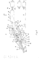
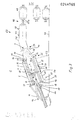
- the device for carrying out the method is characterized in that the filter consists of an outer fine filter and a coarse filter arranged at a distance therefrom, that the piston with the fine filter and the coarse filter which is displaceable coaxially to the central axis thereof is in operative engagement and that on the section facing away from the fecal sludge inlet opening the filter drum has a solids outlet opening which is connected to a solids depositing device.
- the device 1 consists of a filter chamber 2 which is supported on a floor 53 by means of supports 52 inclined upwards at an angle to the horizontal. For example, an angle of inclination of 20 ° has proven to be expedient.
- the angle of inclination is fundamentally to be designed so that an optimal vortex flow of the pressed-in fecal sludge is achieved in the filter chamber 2.
- the swirl chamber 2 there are a coarse filter 5, a fine filter 4 and a piston 7 which is connected to a hydraulic cylinder 3 by means of a piston rod 11.
- a hydraulic piston 15, which can be acted upon by hydraulic oil, is arranged in the hydraulic cylinder 3 on the piston rod 11.
- a fecal sludge inlet tube 16 is guided through the chamber bottom 12, which with means of a schematically illustrated shut-off valve 46 can be closed.
- a conical outlet funnel 36 is arranged, the outlet 37 of which is inserted into a guide tube 40.
- the guide tube 40 is assigned to a solid packaging device 10, which is not shown in detail.
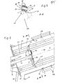
- a depot outlet pipe 59 at the outlet 37 of the outlet funnel 36 to form a solid depositing device 63, to the outlet of which a hose 60 can be attached.
- This hose can be connected to the depot cover 62 of a depot, which can be designed to be movable on wheels (FIG. 4).
- the depot 61 is separated from the hose 60 and replaced by a new one. The faecal solids located in the depot 61 are removed for further treatment.
- the piston rod 11 is sealed to the filter chamber 19 by a stuffing box 13 in the area of the chamber bottom 12.
- the piston rod 11 is sealed off from the pressure chamber of the hydraulic cylinder 3 by means of a further stuffing box 14, which is formed on the hydraulic cylinder at a distance from the chamber bottom 12. This prevents any pressure oil escaping from the hydraulic cylinder 3 from entering the filter chamber 19 and burdening the sewage sludge treatment.
- the fecal sludge inlet tube 16 is guided through the lower chamber bottom 12 so that it can be brought into engagement with a closure device 17 on the outlet side.
- the closure device 17 is formed on the piston 7.
- This has an opening 18 which can be closed by means of a flap 20 assigned to the filter space 19.
- the opening 18 is arranged coaxially with the outlet opening 21 of the fecal sludge inlet tube 16.
- the flap 20 has a weight such that it rests on the jet of fecal sludge entering through the opening 18, whereby it is swirled and deflected towards the chamber wall 32 of the filter chamber 2. This prevents the jet of fecal sludge from penetrating and damaging the filtrate plug replacement 38 arranged in the outlet funnel 36 when the device 1 is started up under appropriate pressure over the entire length of the filter chamber 2.
- this filtrate plug replacement 38 serves to maintain the required pressure in the filter space 19 and to prevent unfiltered fecal sludge from penetrating to the solid packaging device 10.
- the coarse filter 5 and the fine filter 4 are formed by rods 22, 23 attached to the chamber bottom 12 and extending over the length of the filter chamber 2.
- the end sections 56 of the rods 23 are angled outwards and connected to the filter chamber 2. It is also possible to close the end sections 56 with the outlet funnel 36 connect. It is also possible to form the end sections 56 of the rods 23 coaxially with their longitudinal axes. In this case, the rods 23 are connected to the filter chamber 2 by means of supports 58 (FIG. 4).
- the end sections 55 of the rods 22 are designed to be angled in a manner directed towards the central axis 6 of the filter chamber 2. In the spaces 24, 25 between the rods 22, 23, wipers 26, 27 connected to the piston 7 are guided.
- the rods 22, 23 have a rectangular cross section and are arranged such that their long side surfaces 28, 29 are aligned radially to the central axis 6 of the filter chamber 2.
- the spaces 25, 26 are wedge-shaped in the direction of flow, so that no filter material can jam in the spaces 25, 26 and the faecal sludge cleaned from solids penetrate into the drain chamber 54 of the filter chamber 2 and can be discharged via the water outlet connection 31 to the sewage treatment plant.
- the piston 7 consists of a central piston plate 49, on the circumference of which the wipers 26 are arranged radially.
- an annular piston 51 is provided which is connected to the wipers 26.
- the radially outward wipers 27 are formed on the outer circumference of the annular piston 51 and are arranged in the spaces 25.
- pressurized water can be placed in the filter chamber directed nozzles 33. These nozzles 33 are connected to one another and to a pressurized water valve 48 via a ring line 34.
- the inner surface 39 of the outlet funnel 36 is arranged as nozzles 33 which can be acted upon as pressurized water. These nozzles 33 are connected to one another and to a pressurized water valve 48 via a ring line 34.
- the inner surface 39 of the outlet funnel 36 is designed as a sliding surface.
- a special insert made of sheet metal or plastic with a sliding surface in the outlet funnel 36.
- the outlet funnel 36 is filled with a filtrate plug replacement 38 to maintain a sufficient pressure in the filter chamber 2. This can e.g. Straw or wood wool. It is advantageous to choose 38 such substances that are biodegradable as a filtrate plug replacement.
- the filtrate plug replacement 38 is also fed to the solid packaging device 10 during the further operation of the device 1 when the fecal solids are pressed out.
- inspection openings 45 which can be closed at various points are provided there.
- the throughput of a batch of faecal sludge takes place in three stages.
- a sludge wagon presses fecal sludge 16 into the filter space 19 via the fecal sludge inlet pipe, a uniform vortex flow being generated in the filter space 19.
- This vortex flow enables solids in the faecal sludge to adhere to the coarse filter 5 or fine filter 4 and the residual liquid with the fine constituents is fed to the sewage treatment plant via the water outlet connection 31.
- the piston 7 is displaced by actuating the hydraulic cylinder 3 to the upper end section 35, the wipers 26, 27 conveying the solids from the rods 22, 23 upward into the outlet funnel 36 .
- the filtrate reaches the area of the solid packaging device 10 with the filtrate plug replacement 38 and is packed there to the bags or bales 43.
- the filtrate is supplied to the depot 61 via the depot outlet pipe 59 and the hose 60. There is no special packaging in bags or bales 43 in this case.
- the residual water obtained during the compression is discharged via the water discharge nozzle 44 at the outlet 37 of the outlet funnel 36.
- the device 1 enables an odor-free mode of operation due to its closed system. Fast batch throughput is possible even with large sludge trucks, although the construction volume is kept relatively small. As a result, the manufacturing costs are relatively low, as are the operating costs, since multiple con transhipment with special odor control devices is no longer necessary.
- the device 1 is further characterized by a low susceptibility to malfunction, since there are no rotating parts and the mechanical wear is only slight.
- the device is controlled with an electronic or electromagnetic control device (not shown in more detail). This acts on the shut-off valve 26 of the fecal sludge inlet tube 16, the hydraulic cylinder 3 and the pressurized water valve 48 assigned to the nozzles 33.
- the operation of the device 1 can be controlled manually or automatically by means of this control device.
- the control device has relays, time relays, switches and the like which are known per se and which are connected to one another in a suitable electrical circuit.
Landscapes
- Chemical & Material Sciences (AREA)
- Chemical Kinetics & Catalysis (AREA)
- Health & Medical Sciences (AREA)
- Life Sciences & Earth Sciences (AREA)
- Engineering & Computer Science (AREA)
- Hydrology & Water Resources (AREA)
- Public Health (AREA)
- Water Supply & Treatment (AREA)
- Treatment Of Sludge (AREA)
- Filtration Of Liquid (AREA)
Priority Applications (1)
| Application Number | Priority Date | Filing Date | Title |
|---|---|---|---|
| AT87106290T ATE44569T1 (de) | 1986-05-09 | 1987-04-30 | Verfahren zum ausscheiden von feststoffen aus faekalschlamm und vorrichtung zur durchfuehrung des verfahrens. |
Applications Claiming Priority (2)
| Application Number | Priority Date | Filing Date | Title |
|---|---|---|---|
| DE19863615681 DE3615681A1 (de) | 1986-05-09 | 1986-05-09 | Verfahren zum ausscheiden von feststoffen aus faekalschlamm und vorrichtung zur durchfuehrung des verfahrens |
| DE3615681 | 1986-05-09 |
Publications (3)
| Publication Number | Publication Date |
|---|---|
| EP0244765A2 true EP0244765A2 (fr) | 1987-11-11 |
| EP0244765A3 EP0244765A3 (en) | 1988-01-27 |
| EP0244765B1 EP0244765B1 (fr) | 1989-07-12 |
Family
ID=6300485
Family Applications (1)
| Application Number | Title | Priority Date | Filing Date |
|---|---|---|---|
| EP87106290A Expired EP0244765B1 (fr) | 1986-05-09 | 1987-04-30 | Procédé pour la séparation de substances solides de boue fécale et dispositif pour la mise en oeuvre de ce procédé |
Country Status (3)
| Country | Link |
|---|---|
| EP (1) | EP0244765B1 (fr) |
| AT (1) | ATE44569T1 (fr) |
| DE (2) | DE3615681A1 (fr) |
Cited By (5)
| Publication number | Priority date | Publication date | Assignee | Title |
|---|---|---|---|---|
| EP0340377A1 (fr) * | 1988-05-05 | 1989-11-08 | HYDROPRESS WALLANDER & CO AB | Procédé pour traiter les ordures et dispositif pour effectuer le procédé |
| DE4222128A1 (de) * | 1991-07-05 | 1993-01-14 | Bischof Rudolf Gmbh | Verfahren und vorrichtung zur verbesserung der aufbereitung von abwasser-feststoffen, sand, muell o. dgl. |
| EP0557030A1 (fr) * | 1992-02-15 | 1993-08-25 | JONES & ATTWOOD LIMITED | Appareil de lavage |
| EP0571902A3 (fr) * | 1992-05-25 | 1994-03-02 | Cirio Bertolli De Rica Societa | |
| NL1013113C2 (nl) * | 1999-09-22 | 2001-03-23 | Coenraadts Machf B V | Inrichting voor het filtreren van vloeistoffen, in het bijzonder eierproducten. |
Families Citing this family (3)
| Publication number | Priority date | Publication date | Assignee | Title |
|---|---|---|---|---|
| AT393118B (de) * | 1989-12-01 | 1991-08-26 | Guggemos Horst | Einrichtung zum entwaessern von schlaemmen |
| DE9207706U1 (de) * | 1992-06-06 | 1992-10-01 | Clayton, Mike | Vorrichtung zur Entfernung von Schlauch- oder rohrförmigen Filtermitteln |
| CN104722119A (zh) * | 2013-12-18 | 2015-06-24 | 四川高精净化设备有限公司 | 一种滤孔的清洁装置 |
Family Cites Families (6)
| Publication number | Priority date | Publication date | Assignee | Title |
|---|---|---|---|---|
| FR383924A (fr) * | 1907-01-21 | 1908-03-24 | Jean Chabanel | Procédé et appareils pour l'assainissement des villes |
| DE1123271B (de) * | 1959-12-18 | 1962-02-08 | Rheinstahl Eisenwerke Muelheim | Kolbenpresse zum Entwaessern von Schlaemmen od. dgl. mineralischer oder vegetabilischer Art, insbesondere zur Feinstkornentwaesserung von Kohlenschlaemmen |
| GB1059447A (en) * | 1963-10-18 | 1967-02-22 | Lamort E & M | Apparatus for the filtration of liquids containing in suspension, fine, solid particles |
| CH598861A5 (fr) * | 1973-07-25 | 1978-05-12 | Muanyagipari Kutato Intezet | |
| US4377108A (en) * | 1981-05-26 | 1983-03-22 | M. Schaerer A.G. | Coffee-making machine |
| NO154666C (no) * | 1984-06-01 | 1986-11-26 | Jan Oddvar From | Fremgangsmaate og innretning for aa fraskille og avvanne grovt materiale fra avloepsvann. |
-
1986
- 1986-05-09 DE DE19863615681 patent/DE3615681A1/de not_active Withdrawn
-
1987
- 1987-04-30 AT AT87106290T patent/ATE44569T1/de not_active IP Right Cessation
- 1987-04-30 EP EP87106290A patent/EP0244765B1/fr not_active Expired
- 1987-04-30 DE DE8787106290T patent/DE3760310D1/de not_active Expired
Cited By (6)
| Publication number | Priority date | Publication date | Assignee | Title |
|---|---|---|---|---|
| EP0340377A1 (fr) * | 1988-05-05 | 1989-11-08 | HYDROPRESS WALLANDER & CO AB | Procédé pour traiter les ordures et dispositif pour effectuer le procédé |
| DE4222128A1 (de) * | 1991-07-05 | 1993-01-14 | Bischof Rudolf Gmbh | Verfahren und vorrichtung zur verbesserung der aufbereitung von abwasser-feststoffen, sand, muell o. dgl. |
| EP0557030A1 (fr) * | 1992-02-15 | 1993-08-25 | JONES & ATTWOOD LIMITED | Appareil de lavage |
| US5378375A (en) * | 1992-02-15 | 1995-01-03 | Jones & Attwood Limited | Apparatus and method of washing screenings |
| EP0571902A3 (fr) * | 1992-05-25 | 1994-03-02 | Cirio Bertolli De Rica Societa | |
| NL1013113C2 (nl) * | 1999-09-22 | 2001-03-23 | Coenraadts Machf B V | Inrichting voor het filtreren van vloeistoffen, in het bijzonder eierproducten. |
Also Published As
| Publication number | Publication date |
|---|---|
| EP0244765B1 (fr) | 1989-07-12 |
| DE3760310D1 (en) | 1989-08-17 |
| DE3615681A1 (de) | 1987-11-12 |
| EP0244765A3 (en) | 1988-01-27 |
| ATE44569T1 (de) | 1989-07-15 |
Similar Documents
| Publication | Publication Date | Title |
|---|---|---|
| DE102015116626B3 (de) | Vorrichtung und Verfahren zur Abscheidung von Feststoffpartikeln aus einer gelöste Gase enthaltenden Suspension | |
| DE3122131C2 (de) | Vorrichtung zur Entnahme und Entwässerung von Feststoffen aus Flüssigkeiten, insbesondere aus Gerinnen von Kläranlagen | |
| EP0244765B1 (fr) | Procédé pour la séparation de substances solides de boue fécale et dispositif pour la mise en oeuvre de ce procédé | |
| DE19636254C2 (de) | Vorrichtung und Verfahren zum Filtern von Suspensionen | |
| DE19924130B4 (de) | Verfahren zur Filtration von Schadstoffen enthaltenen Gasen und Vorrichtung zur Durchführung des Verfahrens | |
| EP1516672B1 (fr) | Procédé et dispositif pour la séparation de matière organique de matière inorganique | |
| DE3874126T2 (de) | Verfahren zum behandeln von abfall und vorrichtung zum ausfuehren des verfahrens. | |
| DE4125565A1 (de) | Verfahren und vorrichtung zur aufbereitung von rechengut an klaeranlagen | |
| DE2937965A1 (de) | Vorrichtung zur aeroben verottung von muell o.ae. | |
| DE3007345A1 (de) | Absauggeraet, insbesondere fuer gewerbliche oder industrielle zwecke | |
| EP0108196B1 (fr) | Procédé pour remplir et vider un silo | |
| DE4102965C2 (de) | Vorrichtung und Verfahren zum Fördern eines feinkörnigen bis staubförmigen Brennstoffes in einen unter erhöhtem Druck stehenden Vergasungsreaktor | |
| EP0429031B1 (fr) | Dispositif pour séparer, en particulier, des déchets contaminés par de l'huile, comprenant de l'acier ou du métal en feuille et du papier | |
| DE8103406U1 (de) | Muellpressvorrichtung fuer fluessigkeitshaltige abfaelle | |
| EP0318732A2 (fr) | Dispositif pour exprimer les liquides d'un produit en vrac et/ou à faculté d'écoulement | |
| DE4140770A1 (de) | Abwasserklaeranlage | |
| EP0986520B1 (fr) | Silo a boues | |
| DE4328071A1 (de) | Vorrichtung zur Entnahme von schwerfließenden Schüttgütern aus einem Silo | |
| AT393118B (de) | Einrichtung zum entwaessern von schlaemmen | |
| EP0903440B1 (fr) | Procédé et dispositif pour amélioration des sols avec un liant a poudre | |
| DE3802415A1 (de) | Verfahren und anlage zur herstellung eines transportierbaren erzeugnisses aus mechanischen verunreinigungen von abwaessern | |
| DE2531845A1 (de) | Zuckersilo sowie verfahren zu dessen entleerung | |
| DE588406C (de) | Schlitzbunker mit Trog, in dem eine Austragvorrichtung angeordnet ist | |
| DE2612385B1 (de) | Vorrichtung zum entw[ssern von schlamm | |
| DE2401627A1 (de) | Verfahren zum filtrieren von fluessigkeiten und druckfilter mit losem filtermaterial zur durchfuehrung dieses verfahrens |
Legal Events
| Date | Code | Title | Description |
|---|---|---|---|
| PUAI | Public reference made under article 153(3) epc to a published international application that has entered the european phase |
Free format text: ORIGINAL CODE: 0009012 |
|
| AK | Designated contracting states |
Kind code of ref document: A2 Designated state(s): AT BE CH DE ES FR GB GR IT LI LU NL SE |
|
| PUAL | Search report despatched |
Free format text: ORIGINAL CODE: 0009013 |
|
| AK | Designated contracting states |
Kind code of ref document: A3 Designated state(s): AT BE CH DE ES FR GB GR IT LI LU NL SE |
|
| 17P | Request for examination filed |
Effective date: 19880418 |
|
| 17Q | First examination report despatched |
Effective date: 19881110 |
|
| GRAA | (expected) grant |
Free format text: ORIGINAL CODE: 0009210 |
|
| AK | Designated contracting states |
Kind code of ref document: B1 Designated state(s): AT BE CH DE ES FR GB GR IT LI LU NL SE |
|
| PG25 | Lapsed in a contracting state [announced via postgrant information from national office to epo] |
Ref country code: BE Effective date: 19890712 Ref country code: GR Free format text: LAPSE BECAUSE OF FAILURE TO SUBMIT A TRANSLATION OF THE DESCRIPTION OR TO PAY THE FEE WITHIN THE PRESCRIBED TIME-LIMIT Effective date: 19890712 Ref country code: GB Effective date: 19890712 Ref country code: FR Free format text: THE PATENT HAS BEEN ANNULLED BY A DECISION OF A NATIONAL AUTHORITY Effective date: 19890712 Ref country code: NL Effective date: 19890712 Ref country code: IT Free format text: LAPSE BECAUSE OF FAILURE TO SUBMIT A TRANSLATION OF THE DESCRIPTION OR TO PAY THE FEE WITHIN THE PRESCRIBED TIME-LIMIT;WARNING: LAPSES OF ITALIAN PATENTS WITH EFFECTIVE DATE BEFORE 2007 MAY HAVE OCCURRED AT ANY TIME BEFORE 2007. THE CORRECT EFFECTIVE DATE MAY BE DIFFERENT FROM THE ONE RECORDED. Effective date: 19890712 |
|
| REF | Corresponds to: |
Ref document number: 44569 Country of ref document: AT Date of ref document: 19890715 Kind code of ref document: T |
|
| REF | Corresponds to: |
Ref document number: 3760310 Country of ref document: DE Date of ref document: 19890817 |
|
| PG25 | Lapsed in a contracting state [announced via postgrant information from national office to epo] |
Ref country code: ES Free format text: LAPSE BECAUSE OF FAILURE TO SUBMIT A TRANSLATION OF THE DESCRIPTION OR TO PAY THE FEE WITHIN THE PRESCRIBED TIME-LIMIT Effective date: 19891023 |
|
| EN | Fr: translation not filed | ||
| NLV1 | Nl: lapsed or annulled due to failure to fulfill the requirements of art. 29p and 29m of the patents act | ||
| GBV | Gb: ep patent (uk) treated as always having been void in accordance with gb section 77(7)/1977 [no translation filed] | ||
| PG25 | Lapsed in a contracting state [announced via postgrant information from national office to epo] |
Ref country code: LU Free format text: LAPSE BECAUSE OF NON-PAYMENT OF DUE FEES Effective date: 19900430 Ref country code: AT Effective date: 19900430 |
|
| PGFP | Annual fee paid to national office [announced via postgrant information from national office to epo] |
Ref country code: SE Payment date: 19900430 Year of fee payment: 4 |
|
| PGFP | Annual fee paid to national office [announced via postgrant information from national office to epo] |
Ref country code: CH Payment date: 19900508 Year of fee payment: 4 |
|
| PLBE | No opposition filed within time limit |
Free format text: ORIGINAL CODE: 0009261 |
|
| STAA | Information on the status of an ep patent application or granted ep patent |
Free format text: STATUS: NO OPPOSITION FILED WITHIN TIME LIMIT |
|
| 26N | No opposition filed | ||
| PG25 | Lapsed in a contracting state [announced via postgrant information from national office to epo] |
Ref country code: CH Effective date: 19910430 Ref country code: LI Effective date: 19910430 |
|
| PG25 | Lapsed in a contracting state [announced via postgrant information from national office to epo] |
Ref country code: SE Effective date: 19910501 |
|
| REG | Reference to a national code |
Ref country code: CH Ref legal event code: PL |
|
| EUG | Se: european patent has lapsed |
Ref document number: 87106290.7 Effective date: 19911209 |
|
| PGFP | Annual fee paid to national office [announced via postgrant information from national office to epo] |
Ref country code: DE Payment date: 19960826 Year of fee payment: 10 |
|
| PG25 | Lapsed in a contracting state [announced via postgrant information from national office to epo] |
Ref country code: DE Free format text: LAPSE BECAUSE OF NON-PAYMENT OF DUE FEES Effective date: 19980101 |