EP0244878A2 - Commande électromagnétique-hydraulique de soupapes des moteurs à combustion interne - Google Patents
Commande électromagnétique-hydraulique de soupapes des moteurs à combustion interne Download PDFInfo
- Publication number
- EP0244878A2 EP0244878A2 EP87107613A EP87107613A EP0244878A2 EP 0244878 A2 EP0244878 A2 EP 0244878A2 EP 87107613 A EP87107613 A EP 87107613A EP 87107613 A EP87107613 A EP 87107613A EP 0244878 A2 EP0244878 A2 EP 0244878A2
- Authority
- EP
- European Patent Office
- Prior art keywords
- piston
- electromagnet
- valve
- hydraulic cylinder
- armature
- Prior art date
- Legal status (The legal status is an assumption and is not a legal conclusion. Google has not performed a legal analysis and makes no representation as to the accuracy of the status listed.)
- Granted
Links
- 238000002485 combustion reaction Methods 0.000 title claims abstract description 8
- 238000006073 displacement reaction Methods 0.000 abstract description 6
- 230000003292 diminished effect Effects 0.000 abstract 1
- 230000005540 biological transmission Effects 0.000 description 2
- 230000008878 coupling Effects 0.000 description 2
- 238000010168 coupling process Methods 0.000 description 2
- 238000005859 coupling reaction Methods 0.000 description 2
- 230000005284 excitation Effects 0.000 description 2
- 230000002349 favourable effect Effects 0.000 description 2
- 238000010276 construction Methods 0.000 description 1
- 230000003247 decreasing effect Effects 0.000 description 1
- 230000000694 effects Effects 0.000 description 1
- 239000003344 environmental pollutant Substances 0.000 description 1
- 239000000446 fuel Substances 0.000 description 1
- 238000000034 method Methods 0.000 description 1
- 239000000203 mixture Substances 0.000 description 1
- 231100000719 pollutant Toxicity 0.000 description 1
Images
Classifications
-
- F—MECHANICAL ENGINEERING; LIGHTING; HEATING; WEAPONS; BLASTING
- F15—FLUID-PRESSURE ACTUATORS; HYDRAULICS OR PNEUMATICS IN GENERAL
- F15B—SYSTEMS ACTING BY MEANS OF FLUIDS IN GENERAL; FLUID-PRESSURE ACTUATORS, e.g. SERVOMOTORS; DETAILS OF FLUID-PRESSURE SYSTEMS, NOT OTHERWISE PROVIDED FOR
- F15B7/00—Systems in which the movement produced is definitely related to the output of a volumetric pump; Telemotors
- F15B7/02—Systems with continuously-operating input and output apparatus
-
- F—MECHANICAL ENGINEERING; LIGHTING; HEATING; WEAPONS; BLASTING
- F01—MACHINES OR ENGINES IN GENERAL; ENGINE PLANTS IN GENERAL; STEAM ENGINES
- F01L—CYCLICALLY OPERATING VALVES FOR MACHINES OR ENGINES
- F01L1/00—Valve-gear or valve arrangements, e.g. lift-valve gear
- F01L1/02—Valve drive
- F01L1/04—Valve drive by means of cams, camshafts, cam discs, eccentrics or the like
- F01L1/047—Camshafts
-
- F—MECHANICAL ENGINEERING; LIGHTING; HEATING; WEAPONS; BLASTING
- F01—MACHINES OR ENGINES IN GENERAL; ENGINE PLANTS IN GENERAL; STEAM ENGINES
- F01L—CYCLICALLY OPERATING VALVES FOR MACHINES OR ENGINES
- F01L9/00—Valve-gear or valve arrangements actuated non-mechanically
- F01L9/10—Valve-gear or valve arrangements actuated non-mechanically by fluid means, e.g. hydraulic
-
- F—MECHANICAL ENGINEERING; LIGHTING; HEATING; WEAPONS; BLASTING
- F01—MACHINES OR ENGINES IN GENERAL; ENGINE PLANTS IN GENERAL; STEAM ENGINES
- F01L—CYCLICALLY OPERATING VALVES FOR MACHINES OR ENGINES
- F01L9/00—Valve-gear or valve arrangements actuated non-mechanically
- F01L9/20—Valve-gear or valve arrangements actuated non-mechanically by electric means
-
- F—MECHANICAL ENGINEERING; LIGHTING; HEATING; WEAPONS; BLASTING
- F01—MACHINES OR ENGINES IN GENERAL; ENGINE PLANTS IN GENERAL; STEAM ENGINES
- F01L—CYCLICALLY OPERATING VALVES FOR MACHINES OR ENGINES
- F01L2820/00—Details on specific features characterising valve gear arrangements
- F01L2820/03—Auxiliary actuators
- F01L2820/031—Electromagnets
-
- F—MECHANICAL ENGINEERING; LIGHTING; HEATING; WEAPONS; BLASTING
- F02—COMBUSTION ENGINES; HOT-GAS OR COMBUSTION-PRODUCT ENGINE PLANTS
- F02B—INTERNAL-COMBUSTION PISTON ENGINES; COMBUSTION ENGINES IN GENERAL
- F02B1/00—Engines characterised by fuel-air mixture compression
- F02B1/02—Engines characterised by fuel-air mixture compression with positive ignition
- F02B1/04—Engines characterised by fuel-air mixture compression with positive ignition with fuel-air mixture admission into cylinder
Definitions
- the present application relates to a valve train for internal combustion engines, i. H. for four-stroke gasoline or diesel engines according to the preamble of claim 1.
- Such machines have at least 2 valves per cylinder, which according to the currently preferred technique are pressed into their closed position by spring force and thereby brought into their open position in that a force which counteracts and exceeds the spring force is applied to the valve stem; this in such a way that cams are mounted on an auxiliary shaft driven by the crankshaft at half the speed, which apply the required force to the valve tappets via rocker arms.
- Electromagnetic valve trains are already known from DE-A-33 11 250 and 30 24 109.
- an attempt is made to close the valve, which is designed as an armature of an electromagnet, over the selected displacement path (which can be a few mm, for example, in a motor vehicle engine of 100 KW) by means of Excitement to move the former.
- This requires relatively large electromagnets, which are not only expensive, but also often difficult to accommodate in the immediate vicinity of the engine block.
- the object of the present invention is to enable a greater valve lift while basically adhering to the conventional design of the aforementioned motors and at the same time to eliminate parts which are susceptible to wear. This is intended to achieve a more favorable control behavior of the valves.
- the hydraulic power transmission 1 can translate the movement of the first piston in that the second piston has a noticeably smaller cross section than the first piston.
- the former then follows the movement imposed by the latter with a stroke that is enlarged in relation to the cross-sectional areas when the overall system is closed.
- the movement of the pistons in their cylinders is largely wear-free due to the lack of transverse forces that stress the sliding surfaces.
- the armature of the proposed first electromagnet only needs to be informed of a very small displacement path in the order of magnitude of 1 to 1.5 mm, for which relatively low electromagnetic forces are sufficient. This slight movement is then increased by the hydraulic ratio to the desired valve lift.
- the return of the armature to its initial position when the electromagnet is de-energized can be effected in a conventional manner by the force of a return spring.
- this return spring can be dispensed with in an embodiment of the invention according to claim 2, or its strength can be reduced to the extent which is sufficient to compensate for mechanical play if a special electromagnet is present for each movement device of the primary piston, which is mutually excited with the other.
- the differential piston arrangement has the effect that a displacement of one piston, no matter in which direction, always results in a corresponding displacement of the other piston.
- a pot magnet appears to be particularly suitable for use in the construction described, as proposed in claim 3.
- the second piston and the valve stem with the molded valve plate can be made in one piece, which also further reduces the possibility of play in the transmission.
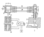
- FIG. 1 An embodiment of the invention is shown in the drawing, namely in the longitudinal axial section.
- the figure partially shows the combustion chamber 1 of a cylinder of an internal combustion engine, to which a fuel-air mixture is supplied via an intake duct 2; an outlet valve can be designed in basically the same way.
- the intake duct 2 is closed off from the combustion chamber 1 by a valve disk 4, which forms a unit with a tappet 5.
- the valve 4 is loaded in the direction of its closed position by a helical spring 6, which is supported on an abutment 7.
- the first piston 12 is made in one piece with an armature 19.
- the armature 19 is in contact with a first electromagnet 20 or a second electromagnet 21, depending on the alternating excitation to be carried out.
- the air gap s to the electromagnet removed in each case is only about 1 to 1.5 mm in size, so that relatively weak and thus small electromagnets can be used. This is particularly the case when, as shown here, it is not necessary to work against a strong return spring, but rather a spring 6 which presses the valve plate 4 into its closed position only serves to compensate for play and can be dimensioned correspondingly weak.
- the excitation of the electromagnets 20, 21 takes place alternately by a control unit 26, in which not only the respective, for. B. on a crankshaft 27 decreased speed of the machine, but also other operating values that are detected by sensors 28 not described here. In this way, the valve closing times that correspond most precisely to the respective operating state can be controlled.
Landscapes
- Engineering & Computer Science (AREA)
- Mechanical Engineering (AREA)
- General Engineering & Computer Science (AREA)
- Physics & Mathematics (AREA)
- Fluid Mechanics (AREA)
- Valve Device For Special Equipments (AREA)
Priority Applications (1)
| Application Number | Priority Date | Filing Date | Title |
|---|---|---|---|
| AT87107613T ATE57989T1 (de) | 1985-02-11 | 1986-01-30 | Elektromagnetisch-hydraulischer ventiltrieb fuer verbrennungskraftmaschinen. |
Applications Claiming Priority (4)
| Application Number | Priority Date | Filing Date | Title |
|---|---|---|---|
| DE3504639 | 1985-02-11 | ||
| DE19853504639 DE3504639A1 (de) | 1985-02-11 | 1985-02-11 | Hydraulische steuerung fuer ventile von verbrennungskraftmaschinen |
| DE3534388 | 1985-09-26 | ||
| DE3534388 | 1985-09-26 |
Related Parent Applications (1)
| Application Number | Title | Priority Date | Filing Date |
|---|---|---|---|
| EP86101217.7 Division | 1986-01-30 |
Publications (3)
| Publication Number | Publication Date |
|---|---|
| EP0244878A2 true EP0244878A2 (fr) | 1987-11-11 |
| EP0244878A3 EP0244878A3 (en) | 1987-12-23 |
| EP0244878B1 EP0244878B1 (fr) | 1990-10-31 |
Family
ID=25829292
Family Applications (2)
| Application Number | Title | Priority Date | Filing Date |
|---|---|---|---|
| EP87107613A Expired - Lifetime EP0244878B1 (fr) | 1985-02-11 | 1986-01-30 | Commande électromagnétique-hydraulique de soupapes des moteurs à combustion interne |
| EP86101217A Expired EP0191376B1 (fr) | 1985-02-11 | 1986-01-30 | Entraînement de soupape avec transmission hydraulique |
Family Applications After (1)
| Application Number | Title | Priority Date | Filing Date |
|---|---|---|---|
| EP86101217A Expired EP0191376B1 (fr) | 1985-02-11 | 1986-01-30 | Entraînement de soupape avec transmission hydraulique |
Country Status (4)
| Country | Link |
|---|---|
| EP (2) | EP0244878B1 (fr) |
| JP (1) | JPS61187505A (fr) |
| DE (2) | DE3675387D1 (fr) |
| ES (1) | ES8702577A1 (fr) |
Cited By (8)
| Publication number | Priority date | Publication date | Assignee | Title |
|---|---|---|---|---|
| FR2638484A1 (fr) * | 1988-10-28 | 1990-05-04 | Daimler Benz Ag | Dispositif d'actionnement, operant hydrauliquement, pour une soupape de lancement, notamment dans un moteur a combustion interne |
| EP0405187A1 (fr) * | 1989-06-27 | 1991-01-02 | FEV Motorentechnik GmbH & Co. KG | Dispositif électromagnétique de positionnement |
| DE4004876A1 (de) * | 1990-02-16 | 1991-09-26 | Ulrich Karrer | Elektrisch betaetigte ventilsteuerung fuer periodisch betriebene ventile fuer kraftmaschinen |
| WO1992000460A1 (fr) * | 1990-06-29 | 1992-01-09 | Pi-Patente Gesellschaft Mit Beschränkter Haftung (Gmbh) | Dispositif d'entrainement d'un outil anime d'un mouvement alternatif axial |
| DE19829857A1 (de) * | 1998-07-05 | 2000-01-13 | Bayerische Motoren Werke Ag | Brennkraftmaschine mit einem pneumatischen und/oder hydraulischen Aktuator für ein Gaswechsel-Hubventil |
| EP1215369A3 (fr) * | 2000-12-12 | 2003-01-29 | Jenbacher Aktiengesellschaft | Commande hydraulique variable pour soupape |
| DE102004057574A1 (de) * | 2004-11-30 | 2006-06-08 | Luk Lamellen Und Kupplungsbau Beteiligungs Kg | Variabler Ventiltrieb einer Brennkraftmaschine |
| WO2013000155A1 (fr) * | 2011-06-30 | 2013-01-03 | Lio Pang-Chian | Dispositif de télécommande à transmission hydraulique |
Families Citing this family (8)
| Publication number | Priority date | Publication date | Assignee | Title |
|---|---|---|---|---|
| SU1621816A3 (ru) * | 1987-02-10 | 1991-01-15 | Интератом Гмбх (Фирма) | Гидравлическое устройство управлени клапанами двигател внутреннего сгорани |
| DE8717456U1 (de) * | 1987-08-26 | 1988-12-29 | INTERATOM GmbH, 5060 Bergisch Gladbach | Rotationskolbenpumpe mit ungleichmäßiger Pumpleistung, insbesondere zur Ventilsteuerung von Verbrennungskraftmaschinen |
| DE19723924B4 (de) * | 1997-06-06 | 2008-02-28 | Hoffmann, Bernhard | Elektrischer Linearmotor |
| DK176152B1 (da) * | 2000-07-10 | 2006-10-16 | Man B & W Diesel As | Fremgangsmåde til aktivering af en udstödsventil til en forbrændingsmotor samt en sådan udstödsventil |
| DE102005017482B4 (de) | 2005-04-15 | 2007-05-03 | Compact Dynamics Gmbh | Gaswechselventilaktor für einen ventilgesteuerten Verbrennungsmotor |
| DE102005017481B4 (de) | 2005-04-15 | 2007-08-30 | Compact Dynamics Gmbh | Linearaktor |
| CN105822377B (zh) * | 2016-05-04 | 2018-05-18 | 哈尔滨工程大学 | 电磁控制增压式配气系统 |
| CN106958470A (zh) * | 2017-05-23 | 2017-07-18 | 海南大学 | 电磁液压配气机构 |
Citations (2)
| Publication number | Priority date | Publication date | Assignee | Title |
|---|---|---|---|---|
| DE3024109A1 (de) | 1980-06-27 | 1982-01-21 | Pischinger, Franz, Prof. Dipl.-Ing. Dr.Techn., 5100 Aachen | Elektromagnetisch arbeitende stelleinrichtung |
| DE3311250A1 (de) | 1983-03-28 | 1984-10-11 | FEV Forschungsgesellschaft für Energietechnik und Verbrennungsmotoren mbH, 5100 Aachen | Vorrichtung fuer elektromagnetisch arbeitende stelleinrichtungen |
Family Cites Families (13)
| Publication number | Priority date | Publication date | Assignee | Title |
|---|---|---|---|---|
| FR471102A (fr) * | 1913-10-02 | 1914-10-15 | Ettore Bugatti | Commande hydraulique de moteur avec piston de réglage formant compensateur |
| FR573596A (fr) * | 1922-10-02 | 1924-06-26 | Perfectionnements apportés à la commande de certains éléments, en mouvement périodique, de moteurs, notamment à celle d'éléments, tels que les soupapes, les organes d'injection et les dispositifs de graissage, dont le mouvement alterne avec des périodes de repos | |
| DE467440C (de) * | 1927-05-08 | 1928-10-25 | Waggon Und Maschb Akt Ges Goer | Druckfluessigkeitssteuerung fuer Ventile von Brennkraftmaschinen |
| FR932936A (fr) * | 1946-07-31 | 1948-04-06 | Perfectionnement aux commandes hydrauliques d'organes de moteurs et de machines diverses | |
| FR941789A (fr) * | 1947-01-16 | 1949-01-20 | Dispositif de commande hydraulique de soupapes | |
| US2635544A (en) * | 1948-03-06 | 1953-04-21 | Lossau Earl | Hydraulic valve lifting mechanism |
| DE1002563B (de) * | 1951-07-09 | 1957-02-14 | Gerhard Schaller | Hydraulischer Ventilantrieb fuer Brennkraftmaschinen |
| FR1380557A (fr) * | 1963-10-02 | 1964-12-04 | Glaenzer Spicer Sa | Tourillon |
| DE2057639A1 (de) * | 1969-12-05 | 1971-06-24 | Inst Regelungstechnik | Digitaler hydraulischer Stellantrieb |
| GB1591421A (en) * | 1977-01-12 | 1981-06-24 | Lucas Industries Ltd | Valve operating mechanism |
| DE2907033A1 (de) * | 1979-02-23 | 1980-09-04 | Bosch Gmbh Robert | Einrichtung zur betaetigung eines gaswechselventils bei brennkraftmaschinen |
| DE3046891A1 (de) * | 1980-12-12 | 1982-07-15 | Robert Bosch Gmbh, 7000 Stuttgart | Elektromagnet |
| GB2122257B (en) * | 1982-06-04 | 1986-04-16 | Paul Julian Moloney | Valve operating mechanism for internal combustion and like-valved engines |
-
1986
- 1986-01-30 DE DE8787107613T patent/DE3675387D1/de not_active Expired - Fee Related
- 1986-01-30 EP EP87107613A patent/EP0244878B1/fr not_active Expired - Lifetime
- 1986-01-30 DE DE8686101217T patent/DE3660265D1/de not_active Expired
- 1986-01-30 EP EP86101217A patent/EP0191376B1/fr not_active Expired
- 1986-02-05 JP JP61023652A patent/JPS61187505A/ja active Pending
- 1986-02-10 ES ES551808A patent/ES8702577A1/es not_active Expired
Patent Citations (2)
| Publication number | Priority date | Publication date | Assignee | Title |
|---|---|---|---|---|
| DE3024109A1 (de) | 1980-06-27 | 1982-01-21 | Pischinger, Franz, Prof. Dipl.-Ing. Dr.Techn., 5100 Aachen | Elektromagnetisch arbeitende stelleinrichtung |
| DE3311250A1 (de) | 1983-03-28 | 1984-10-11 | FEV Forschungsgesellschaft für Energietechnik und Verbrennungsmotoren mbH, 5100 Aachen | Vorrichtung fuer elektromagnetisch arbeitende stelleinrichtungen |
Cited By (10)
| Publication number | Priority date | Publication date | Assignee | Title |
|---|---|---|---|---|
| FR2638484A1 (fr) * | 1988-10-28 | 1990-05-04 | Daimler Benz Ag | Dispositif d'actionnement, operant hydrauliquement, pour une soupape de lancement, notamment dans un moteur a combustion interne |
| EP0405187A1 (fr) * | 1989-06-27 | 1991-01-02 | FEV Motorentechnik GmbH & Co. KG | Dispositif électromagnétique de positionnement |
| DE3920931A1 (de) * | 1989-06-27 | 1991-01-03 | Fev Motorentech Gmbh & Co Kg | Elektromagnetisch arbeitende stelleinrichtung |
| DE4004876A1 (de) * | 1990-02-16 | 1991-09-26 | Ulrich Karrer | Elektrisch betaetigte ventilsteuerung fuer periodisch betriebene ventile fuer kraftmaschinen |
| WO1992000460A1 (fr) * | 1990-06-29 | 1992-01-09 | Pi-Patente Gesellschaft Mit Beschränkter Haftung (Gmbh) | Dispositif d'entrainement d'un outil anime d'un mouvement alternatif axial |
| US5337565A (en) * | 1990-06-29 | 1994-08-16 | Pi-Patent Gesellschaft Mit Beschraenkter Haftung (Gmbh) | Device for driving a tool movable to and fro in axial direction |
| DE19829857A1 (de) * | 1998-07-05 | 2000-01-13 | Bayerische Motoren Werke Ag | Brennkraftmaschine mit einem pneumatischen und/oder hydraulischen Aktuator für ein Gaswechsel-Hubventil |
| EP1215369A3 (fr) * | 2000-12-12 | 2003-01-29 | Jenbacher Aktiengesellschaft | Commande hydraulique variable pour soupape |
| DE102004057574A1 (de) * | 2004-11-30 | 2006-06-08 | Luk Lamellen Und Kupplungsbau Beteiligungs Kg | Variabler Ventiltrieb einer Brennkraftmaschine |
| WO2013000155A1 (fr) * | 2011-06-30 | 2013-01-03 | Lio Pang-Chian | Dispositif de télécommande à transmission hydraulique |
Also Published As
| Publication number | Publication date |
|---|---|
| EP0191376A1 (fr) | 1986-08-20 |
| ES8702577A1 (es) | 1986-12-16 |
| DE3660265D1 (en) | 1988-07-07 |
| EP0244878A3 (en) | 1987-12-23 |
| ES551808A0 (es) | 1986-12-16 |
| EP0191376B1 (fr) | 1988-06-01 |
| DE3675387D1 (de) | 1990-12-06 |
| JPS61187505A (ja) | 1986-08-21 |
| EP0244878B1 (fr) | 1990-10-31 |
Similar Documents
| Publication | Publication Date | Title |
|---|---|---|
| EP0244878B1 (fr) | Commande électromagnétique-hydraulique de soupapes des moteurs à combustion interne | |
| DE69105721T3 (de) | Ventilsteuervorrichtung. | |
| DE68911484T2 (de) | Ventilsteuerungsvorrichtung für Brennkraftmaschinen. | |
| DE102010008959A1 (de) | Verbrennungsmotor mit variablem Ventiltrieb | |
| DE19712668C1 (de) | Ventilantrieb für Gaswechselventile von Brennkraftmaschinen | |
| DE3428627A1 (de) | Viertakt-brennkraftmaschine | |
| DE68904693T2 (de) | Vorrichtung zum umschalten der betriebsart der ventile in einer brennkraftmaschine. | |
| DE19815112A1 (de) | Anordnung zur variablen Ventilzeitsteuerung und Ventilbetätigung | |
| DE3782035T2 (de) | Ventilantriebmechanismus fuer brennkraftmaschine. | |
| EP1561011A1 (fr) | Systeme d'actionneur oscillant servant a commander la levee d'une soupape de changement des gaz dans la culasse d'un moteur a combustion | |
| DE69303740T2 (de) | Ventilantrieb für eine Brennkraftmaschine | |
| DE69004806T2 (de) | Nockenwelle für mehrventilbrennkraftmaschine. | |
| DE19600536C2 (de) | Vorrichtung zur variablen Steuerung eines Einlaßventils | |
| DE60315923T2 (de) | Eine Brennkraftmaschine mit zwei Einlassventilen für jeden Zylinder und einem elektronischen Regelsystem zum unterschiedlichen und wechselnden Bedienen der zwei Einlassventile | |
| DE19540133C2 (de) | Ventilstößel | |
| DE4332660A1 (de) | Ventiltrieb mit schaltbaren, von zwei Nocken angetriebenen Tassenstößeln für Verbrennungsmotoren | |
| DE4404683C1 (de) | Verfahren zur Minimierung von Spiel in einem Ventiltrieb | |
| DE19706769A1 (de) | Steuervorrichtung für Motorzylinderventil | |
| DE102020109260A1 (de) | Ventilsteuerung für eine Ventilabschaltung und Ventilhubumschaltung | |
| DE10248070B4 (de) | Elektromagnetische Ventilbetätigung mit weichem Anschlag an den Ventilsitz | |
| EP1421262B1 (fr) | Mecanisme de soupape presentant une section d'ouverture de soupape variable | |
| EP1375843B1 (fr) | Moteur à combustion interne | |
| DE3204841A1 (de) | Hubkolben-brennkraftmaschine mit einer vorrichtung zur winkelverstellung der nockenwellen relativ zueinander | |
| DE4406008C2 (de) | Brennkraftmaschine mit zumindest zwei Ein- oder Auslaß-Hubventilen und einer diesen zugeordneten Ventilsteuerung | |
| DE102017111395A1 (de) | Vorrichtung zur Veränderung des Verdichtungsverhältnisses einer Hubkolbenbrennkraftmaschine |
Legal Events
| Date | Code | Title | Description |
|---|---|---|---|
| PUAI | Public reference made under article 153(3) epc to a published international application that has entered the european phase |
Free format text: ORIGINAL CODE: 0009012 |
|
| PUAL | Search report despatched |
Free format text: ORIGINAL CODE: 0009013 |
|
| AC | Divisional application: reference to earlier application |
Ref document number: 191376 Country of ref document: EP |
|
| AK | Designated contracting states |
Kind code of ref document: A2 Designated state(s): AT BE CH DE FR GB IT LI LU SE |
|
| AK | Designated contracting states |
Kind code of ref document: A3 Designated state(s): AT BE CH DE FR GB IT LI LU SE |
|
| 17P | Request for examination filed |
Effective date: 19880125 |
|
| 17Q | First examination report despatched |
Effective date: 19890405 |
|
| GRAA | (expected) grant |
Free format text: ORIGINAL CODE: 0009210 |
|
| AC | Divisional application: reference to earlier application |
Ref document number: 191376 Country of ref document: EP |
|
| AK | Designated contracting states |
Kind code of ref document: B1 Designated state(s): AT BE CH DE FR GB IT LI LU SE |
|
| PG25 | Lapsed in a contracting state [announced via postgrant information from national office to epo] |
Ref country code: SE Effective date: 19901031 Ref country code: BE Effective date: 19901031 |
|
| REF | Corresponds to: |
Ref document number: 57989 Country of ref document: AT Date of ref document: 19901115 Kind code of ref document: T |
|
| REF | Corresponds to: |
Ref document number: 3675387 Country of ref document: DE Date of ref document: 19901206 |
|
| ET | Fr: translation filed | ||
| PGFP | Annual fee paid to national office [announced via postgrant information from national office to epo] |
Ref country code: GB Payment date: 19901217 Year of fee payment: 6 |
|
| ITF | It: translation for a ep patent filed | ||
| PGFP | Annual fee paid to national office [announced via postgrant information from national office to epo] |
Ref country code: FR Payment date: 19910121 Year of fee payment: 6 |
|
| GBT | Gb: translation of ep patent filed (gb section 77(6)(a)/1977) | ||
| PG25 | Lapsed in a contracting state [announced via postgrant information from national office to epo] |
Ref country code: AT Effective date: 19910130 |
|
| ITTA | It: last paid annual fee | ||
| PG25 | Lapsed in a contracting state [announced via postgrant information from national office to epo] |
Ref country code: LU Free format text: LAPSE BECAUSE OF NON-PAYMENT OF DUE FEES Effective date: 19910131 Ref country code: LI Effective date: 19910131 Ref country code: CH Effective date: 19910131 |
|
| PGFP | Annual fee paid to national office [announced via postgrant information from national office to epo] |
Ref country code: DE Payment date: 19910325 Year of fee payment: 6 |
|
| PLBE | No opposition filed within time limit |
Free format text: ORIGINAL CODE: 0009261 |
|
| STAA | Information on the status of an ep patent application or granted ep patent |
Free format text: STATUS: NO OPPOSITION FILED WITHIN TIME LIMIT |
|
| REG | Reference to a national code |
Ref country code: CH Ref legal event code: PL |
|
| 26N | No opposition filed | ||
| PG25 | Lapsed in a contracting state [announced via postgrant information from national office to epo] |
Ref country code: GB Effective date: 19920130 |
|
| GBPC | Gb: european patent ceased through non-payment of renewal fee | ||
| PG25 | Lapsed in a contracting state [announced via postgrant information from national office to epo] |
Ref country code: FR Effective date: 19920930 |
|
| PG25 | Lapsed in a contracting state [announced via postgrant information from national office to epo] |
Ref country code: DE Effective date: 19921001 |
|
| REG | Reference to a national code |
Ref country code: FR Ref legal event code: ST |
|
| PG25 | Lapsed in a contracting state [announced via postgrant information from national office to epo] |
Ref country code: IT Free format text: LAPSE BECAUSE OF NON-PAYMENT OF DUE FEES;WARNING: LAPSES OF ITALIAN PATENTS WITH EFFECTIVE DATE BEFORE 2007 MAY HAVE OCCURRED AT ANY TIME BEFORE 2007. THE CORRECT EFFECTIVE DATE MAY BE DIFFERENT FROM THE ONE RECORDED. Effective date: 20050130 |