EP0245026B1 - Mélangeur optique hétérodyne procurant une réjection des fréquences-images - Google Patents
Mélangeur optique hétérodyne procurant une réjection des fréquences-images Download PDFInfo
- Publication number
- EP0245026B1 EP0245026B1 EP87303853A EP87303853A EP0245026B1 EP 0245026 B1 EP0245026 B1 EP 0245026B1 EP 87303853 A EP87303853 A EP 87303853A EP 87303853 A EP87303853 A EP 87303853A EP 0245026 B1 EP0245026 B1 EP 0245026B1
- Authority
- EP
- European Patent Office
- Prior art keywords
- signal
- signals
- optical
- output
- polarization
- Prior art date
- Legal status (The legal status is an assumption and is not a legal conclusion. Google has not performed a legal analysis and makes no representation as to the accuracy of the status listed.)
- Expired - Lifetime
Links
Images


Classifications
-
- H—ELECTRICITY
- H04—ELECTRIC COMMUNICATION TECHNIQUE
- H04B—TRANSMISSION
- H04B10/00—Transmission systems employing electromagnetic waves other than radio-waves, e.g. infrared, visible or ultraviolet light, or employing corpuscular radiation, e.g. quantum communication
- H04B10/60—Receivers
- H04B10/61—Coherent receivers
- H04B10/614—Coherent receivers comprising one or more polarization beam splitters, e.g. polarization multiplexed [PolMux] X-PSK coherent receivers, polarization diversity heterodyne coherent receivers
-
- H—ELECTRICITY
- H04—ELECTRIC COMMUNICATION TECHNIQUE
- H04B—TRANSMISSION
- H04B10/00—Transmission systems employing electromagnetic waves other than radio-waves, e.g. infrared, visible or ultraviolet light, or employing corpuscular radiation, e.g. quantum communication
- H04B10/60—Receivers
- H04B10/61—Coherent receivers
- H04B10/64—Heterodyne, i.e. coherent receivers where, after the opto-electronic conversion, an electrical signal at an intermediate frequency [IF] is obtained
Definitions
- the present invention relates to optical heterodyne mixers which detect a desired frequency while rejecting interference from any signal at the image frequency.
- Optical heterodyne mixers function to combine an incoming optical signal with an optical signal from a local laser to produce an output signal whose frequency is the frequency difference of the two optical signals.
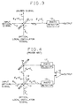
- the simplest known optical mixer configuration is disclosed in, for example, the book "Laser Communication Systems” by W. K. Pratt, John Wiley & Sons, Inc., 1969, and is shown in FIG. 3.
- a received optical signal from a remote source propagating along path 10
- an optical local oscillator signal propagating along path 11 impinge an optical beam-splitter 12.
- Each of the two optical outputs from beam-splitter 12 comprise both a component of the received signal and a component of the local oscillator signal from paths 10 and 11, respectively, which combined components propagate along paths 13 and 14.
- a more efficient mixer is provided by a balanced-mixer configuration shown in FIG. 4 and disclosed, for example, in the article by G. L. Abbes et al. in the Globecom ' 83 Conference Record , Vol. 1, San Diego, Calif., November 28-December 1, 1983, at pages 12.5.1-15.5.6.
- FIG. 4 the basic elements 10-15 of FIG. 3 are shown and function as described hereinabove.
- the signals propagating along path 14, however, are redirected by a device 16 to a second photodetector 17.
- the received signal and the local oscillator signal are both combined and then divided equally by beam-splitter 12 into first and-second beams propagating along paths 13 and 14 which beams are directed to photodetectors 15 and 17, respectively.
- An Image Rejection Mixer (IRM) using a local oscillator (L.O.) signal of frequency f L.O . provides the means to detect simultaneously the two frequencies f L.O. - f IF 1 and f L.O. + f IF 2 and yields the two Intermediate Frequency (IF) signals of frequencies f IF 1 and f IF 2 in first and second outputs, respectively.
- An optical mixer having this feature is highly desirable for optical Local Area Network (LAN) applications and communication systems using Wavelength Division Multiplex (WDM) techniques.
- Implementation of an IRM is simple at microwave frequencies using, for example, the arrangement shown in FIG. 5, or image separation mixers as disclosed in the book "Theory Of Resistive Mixers" by A. A. M.
- the received signal is separated into two equal portions by a 3 dB High Frequency (HF) coupler 20 for propagation along separate paths 21 and 22.
- Individual mixers 23 and 24 combine a local oscillator signal with the received signal portions in paths 21 and 22, respectively, which signals are filtered by respective IF filters 25 and 26.
- a 3 dB IF coupler 27 functions to add the resulting signals on paths 21 and 22 with one coupler output providing the IF signal and the other output providing the IF signal at the image frequency.
- transposition of this circuit to optical frequencies is impractical because the optical dimensions of the circuit must be adjusted to a small fraction of an optical wavelength.
- the Buhrer receiver uses four plane polarisers, a beam splitter, a quarter-wave plate for delaying one of the two orthogonally polarized signals passing therethrough by ⁇ 2 radians and at least one photocell. Where only one photocell is used additional prisms are needed, while when two photocells are required, then an additional ⁇ 2 phase shifter and summing network is required.
- This disclosure forms the basis for the preamble of claim 1.
- the problem remaining in the prior art is to provide an optical image rejection heterodyne mixer which uses substantially all of the received signal and, thereby, provides excellent performance and simple design.
- Patent Abstracts of Japan, vol 8, no. 243 (E-277)[1680], 8th November 1984 (and JP-A-59 122 140) discloses apparatus for obtaining heterodyne detection of an optical signal of indeterminate polarization.
- the signal is first merged with a circularly polarized local oscillator signal.
- the merged signal is then split into two branches having mutually orthogonal polarizations.
- the signal in each branch is then converted into an electrical signal and a base-band signal is derived.
- the base-band signals from the two branches are added to produce the output signal.
- the object is to attain a stable detecting characteristic independently of the polarization state of the input signal.
- optical heterodyne mixers providing image-frequency rejection which comprise a beam-splitter for adding a received optical signal to an optical local oscillator signal.
- the merged beam then enters a polarizing beam-splitter which separates the two orthogonal polarization components of the merged beam.
- Each of the two exiting beams from the polarizing beam-splitter is detected separately by an associated photodetector.
- the resulting two IF currents are added by means of a 3 dB 90 degree IF coupler, where one of the coupler outputs provides the IF signal and the other output yields the IF signal of the image frequency.
- the received optical signal(s) is linearly polarized at 45 degrees relative to the polarization axes of the polarizing beam-splitter, while the optical local oscillator signal is circularly polarized, or vice versa.
- FIG. 1 An arrangement of an optical heterodyne mixer providing image-frequency rejection in accordance with the present invention is shown in FIG. 1.
- a received optical signal and an optical local oscillator (L.O.) signal are received at separate inputs and directed at an optical merging means such as a beam splitter 30 which adds the received signal to the L.O. signal.
- an optical merging means such as a beam splitter 30 which adds the received signal to the L.O. signal.
- one of the input signals either the received signal or the L.O. signal, is linearly polarized, while the other input signal is circularly polarized.
- the received signal can comprise one or more optical signals at different frequencies, where each optical carrier is modulated by a separate information signal.
- the merged beam at the output of beam splitter 30 comprises components of both the received and the L.O. signals and enters a directing means such as and enters a polarizing beam splitter 31 which functions to separate the horizontal and vertical polarization components of the merged beam.
- polarizing beam splitter 31 should be oriented with its polarization axes at 45 degrees relative to the polarization direction of the input signal which is linearly polarized. Such orientation permits the power of the linearly polarized input signal to be equally divided between the transparent and reflective outputs of polarizing beam splitter 31, such that equal components of the linearly polarized input signal in the merged beam enter branches 32 and 33 at the output of beam splitter 31.
- polarizing beam splitter 31 also causes equal components of the circularly polarized input signal in the merged beam to enter branches 32 and 33 concurrent with the above-mentioned components of the linearly polarized input signal.
- the arrangement of FIG. 1 provides the means to maintain the required phase relationships between the in-phase and quadrature signal components independently of the optical path dimensions of the circuit because the L.O. signal and the received signal follow the same optical paths.
- Each of the two exiting beams, comprising components of both the linearly and circularly polarized input signals, in branches 32 and 33 is detected separately in photodetectors 34 and 35, respectively.
- the two resulting Intermediate Frequency (IF) currents from photodetectors 34 and 35 are separately filtered in optional IF filters 36 and 37, respectively, to pass only the IF frequencies, before being added by means of a 3 dB 90 degree IF coupler 38.
- One of the coupler outputs, e.g., output 39 provides, for example, the IF signal while the other output, e.g., output 40, provides, for example, the IF signal of the image frequency.
- Each of the output signals can then be processed by separate receivers as desired.
- IF filters 36 and 37 may not be necessary when the received signal only comprises one optical signal. but may be necessary where more than one optical signal is included in the received signal.
- the received signal is composed of two components; one of radial frequency ⁇ 1 ⁇ ⁇ o and power P 1, the other of radial frequency ⁇ 2 > ⁇ o and power P 2.
- the beam splitter 30, used for adding the signals is assumed to be lossless and nearly transparent to the received signals.
- the x-polarization component traversing polarizing beam splitter 31 arrives at photodiode
- the phase shift introduced by L is thus the same for the two polarization components when the propagation medium is isotropic.
- the two other distances D x and D y represent the remaining path lengths for the beams given by Equations (6) and (7) to reach their respective photodiodes 34 and 35.
- the distances D z and D y are assumed to be nearly equal when measured relative to an IF wavelength but may differ by many optical wavelengths. The first of these two conditions is similarly required in a conventional IRM at microwave frequencies.
- the quantities ⁇ T' and ⁇ R' represent phase shifts caused by polarizing beam splitter 31.
- Equation (8) Planck's constant
- ⁇ the quantum efficiency of the photodiodes 34 and 35, assumed to be the same for the two diodes.
- the last signal processing step consists of adding the currents given by the Equation (8) and (9) by means of a 3 dB 90 degree IF coupler 38 which is assumed to be lossless. Therefore, to satisfy energy conservation, the coupler 38 transforms the input currents into the output signals and The result yields and showing that the IF signals corresponding to the two received optical carriers can be recovered independently.
- beam splitter 30 passes most of the received signal therethrough to polarizing beam splitter 31 but reflects only a small part of the L.O. signal towards polarizing beam splitter 31. Such arrangement, therefore, uses the power supplied by the L.O. source at less than peak efficiency.
- the arrangement of FIG. 2 resolves this minor shortcoming of the arrangement of FIG. 1 by (a) using a 3 dB beam splitter 50 instead of a nearly transparent beam splitter 30, and (b) by adding a polarization rotator 51 in one of the paths provided by 3 dB beam splitter 50 to change the direction of polarization in the signal propagating therethrough by ⁇ 2 radians and thereby use all of the power supplied by the L.O. source.
- 3 dB beam splitter 50 functions to add the received and L.O. signals and transmit equal portions thereof along a first and second output path 53 and 54.
- the polarization rotator 51 is disposed in the second output path 54 of beam splitter 50, as shown in FIG. 2, and not in the first output path 53 of beam splitter 50.
- optional redirecting means 55 and 56 can be disposed in one of the two paths 53 or 54 to redirect the beam in the associated path into the appropriate direction when arriving at polarizing beam splitter 31.
- Optional redirecting means 55 and 56 can each comprise any suitable device such as a mirror, a prism, or a reflecting device.
- Polarizing beam splitter 31 functions as described hereinbefore, which is to be transparent to components in the arriving merged beams in paths 53 and 54, which include a first polarization direction that is parallel to the polarization axis of beam splitter 31 and reflects components in the arriving merged beams that include a second polarization direction which is orthogonal to the polarization axis of polarizing beam splitter 31.
- polarization rotator 51 rotates the beam in path 54 so that its polarization direction is now perpendicular to the beam propagating in path 53 when arriving at polarizing beam splitter 31, the horizontally polarized components from the beam in path 53 and the vertically polarized components from the beam in path 54 are coaxially aligned by polarizing beam splitter 31 for propagation along branch 32 and detection by photodetector 34.
- the vertically polarized components of the beam propagating in path 53 and the horizontally polarized components of the beam propagating along path 54 are coaxially aligned by polarizing beam splitter 31 for propagation along branch 33 and detection by photodetector 35.
- the output from photodetectors 34 and 35 and filters 36 and 37 yields two IF outputs that can be designated by and where L 1 and L 2 are the lengths of the two paths followed by the beams between 3 dB beam splitter 30 and polarizing beam splitter 31 as shown by the dashed lines in FIG. 2.
- Maximum signal is obtained when L 2 and L 1 are selected to satisfy the conditions and This can be achieved if the two IF frequencies are close enough.
- the IF signal powers of Equations (18) and (19) become proportional to the entire power P o' supplied by the L.O. source instead of the fraction P o previously available.
- an L.O. source of lower power is required to achieve quantum noise-limited performance.
- a polarizing beam splitter 31 oriented with its polarization axis at 45 degrees relative to the orientation of the linearly polarized input signal, and the common path being used for the two merged input signals to the input of the polarizing beam splitter, permits proper amplitudes and phases of the polarization components and the outputs of polarizing beam splitter 31 to be obtained. Because of such arrangement, any path length differences occurring between polarizing beam splitter 31 and each of photodetectors 34 and 35 produces only a negligible effect in the output of the two photodetectors because any phase error that may be produced is only proportional to the IF frequency and not to the optical frequency of the received signals.
- the present heterodyne mixers are insensitive to any fluctuations in the optical dimensions of the circuit. It is to be understood, however, that the use of linear and circular polarizations for the L. O. and received input signals is preferred, but that any other polarization combinations in the two input signals which will provide the same phase and amplitude relationships at the photodetector levels will provide the same image rejection performance and also be insensitive to optical dimensions of the circuit.
- 3 dB beam splitter 50 can comprise any suitable device such as, for example. an optical coupling device which will merge the received and L.O. signals and then the divide the merged beam into substantially equal output signals.
- the ⁇ 2 polarization rotator 51 can be included in path 53 rather than in path 54. With this latter arrangement, the signals normally received by photodetector 34 in the arrangement shown in FIG. 2 would be received by photodetector 35 and vice versa, with associated results at the output of IF coupler 38.
Landscapes
- Physics & Mathematics (AREA)
- Electromagnetism (AREA)
- Engineering & Computer Science (AREA)
- Computer Networks & Wireless Communication (AREA)
- Signal Processing (AREA)
- Optical Communication System (AREA)
Claims (5)
- Un mélangeur hétérodyne optique procurant une réjection des fréquences images, comprenant :
une première borne d'entrée destinée à recevoir un signal d'entrée d'oscillateur local optique ayant une polarisation prédéterminée, et une seconde borne d'entrée destinée à recevoir un signal d'entrée d'information optique à une fréquence prédéterminée au-dessus ou au-dessous du signal d'oscillateur local, et ayant une polarisation prédéterminée différente;
des moyens pour combiner les signaux d'entrée pour produire des signaux qui sont dirigés dans une première branche (32) et une seconde branche (33), de façon que :(A) un premier de ces signaux d'entrée produise des signaux dans les branches qui ont des amplitudes et des phases égales, et(B) l'autre des signaux d'entrée produise des signaux dans les branches qui ont des amplitudes égales et ont des phases en quadrature;des premiers et seconds moyens de détection optiques (34, 35), disposés respectivement dans les première et seconde branches, pour détecter les signaux optiques associés respectifs et pour générer respectivement des premier et second signaux de sortie électriques à fréquence intermédiaire (FI); et
des moyens de couplage (38) pour additionner les premier et second signaux de sortie FI, et pour générer (a) un signal FI désiré sur une première sortie de ces moyens (39), et (b) un signal FI à la fréquence image du signal FI désiré sur une seconde sortie de ces moyens (40),
CARACTERISE EN CE QUE les moyens de combinaison comprennent des moyens (30) qui sont destinés à combiner les signaux d'entrée pour qu'ils se propagent le long d'un chemin commun, et
des moyens destinés à recevoir le signal combiné et à diriger vers la première branche des composantes ayant une première direction de polarisation, et vers la seconde branche des composantes ayant une seconde direction de polarisation orthogonale à la première direction de polarisation, ces directions de polarisation et les polarisations prédéterminées des signaux d'entrée étant de nature à satisfaire les conditions (A) et (B). - Un mélangeur hétérodyne optique selon la revendication 1, dans lequel
le premier des premier et second signaux d'entrée polarisés combinés, à la sortie des moyens de combinaison, a une polarisation linéaire qui est orientée à 45 degrés par rapport à l'axe de polarisation des moyens dirigeant les composantes, et le second des premier et second signaux d'entrée combinés, à la sortie des moyens de combinaison, a une polarisation circulaire. - Un mélangeur hétérodyne optique selon la revendication 1 ou 2, dans lequel les moyens recevant le signal combiné et dirigeant les composantes sont constitués par un diviseur de faisceau polarisant.
- Un mélangeur hétérodyne optique selon l'une quelconque des revendications précédentes, dans lequel les moyens de combinaison sont constitués par un diviseur de faisceau optique.
- Un mélangeur hétérodyne optique selon l'une quelconque des revendications précédentes, dans lequel
les moyens de combinaison sont conçus de façon à produire un second signal de sortie se propageant le long d'un second chemin de sortie (54), chacun des premier et second signaux de sortie comprenant des composantes pratiquement égales du signal reçu et du signal d'oscillateur local combinés, et les premier (53) et second (54) chemins de sortie aboutissent à des entrées séparées des moyens recevant le signal combiné et dirigeant les composantes; et
des moyens de rotation (51) sont disposés dans l'un ou l'autre des premier et second chemins de sortie des moyens de combinaison, pour faire tourner de
Applications Claiming Priority (2)
| Application Number | Priority Date | Filing Date | Title |
|---|---|---|---|
| US06/860,825 US4723317A (en) | 1986-05-08 | 1986-05-08 | Optical heterodyne mixers providing image-frequency rejection |
| US860825 | 1986-05-08 |
Publications (3)
| Publication Number | Publication Date |
|---|---|
| EP0245026A2 EP0245026A2 (fr) | 1987-11-11 |
| EP0245026A3 EP0245026A3 (en) | 1989-06-07 |
| EP0245026B1 true EP0245026B1 (fr) | 1993-07-07 |
Family
ID=25334112
Family Applications (1)
| Application Number | Title | Priority Date | Filing Date |
|---|---|---|---|
| EP87303853A Expired - Lifetime EP0245026B1 (fr) | 1986-05-08 | 1987-04-30 | Mélangeur optique hétérodyne procurant une réjection des fréquences-images |
Country Status (5)
| Country | Link |
|---|---|
| US (1) | US4723317A (fr) |
| EP (1) | EP0245026B1 (fr) |
| JP (1) | JPS62272234A (fr) |
| CA (1) | CA1256501A (fr) |
| DE (1) | DE3786418T2 (fr) |
Families Citing this family (16)
| Publication number | Priority date | Publication date | Assignee | Title |
|---|---|---|---|---|
| US4697284A (en) * | 1986-05-08 | 1987-09-29 | American Telephone And Telegraph Company, At&T Bell Laboratories | Single-photodiode optical heterodyne mixers |
| US4723316A (en) * | 1986-05-08 | 1988-02-02 | American Telephone & Telegraph Company, At&T Bell Laboratories | Polarization independent coherent optical heterodyne receivers |
| US4794351A (en) * | 1986-09-29 | 1988-12-27 | American Telephone And Telegraph Company, At&T Bell Laboratories | Optical mixer for upconverting or downconverting an optical signal |
| JPH0734080B2 (ja) * | 1988-10-20 | 1995-04-12 | 富士通株式会社 | コヒーレント光通信用ヘテロダイン検波受信装置 |
| EP0393373A3 (fr) * | 1989-04-21 | 1992-03-11 | Siemens Aktiengesellschaft | Récepteur hétérodyne optique |
| US5115332A (en) * | 1989-07-20 | 1992-05-19 | Fujitsu Limited | Receiver for coherent optical communication |
| US4989212A (en) * | 1990-04-09 | 1991-01-29 | Trw, Inc. | Laser diode phase modulation technique |
| US5027436A (en) * | 1990-04-27 | 1991-06-25 | At&T Bell Laboratories | Optical hybrid for coherent detection systems |
| GB2245117B (en) * | 1990-06-14 | 1994-04-06 | Stc Plc | Optical mixing for heterodyne detection |
| EP0485812B1 (fr) * | 1990-11-15 | 1995-06-21 | Alcatel SEL Aktiengesellschaft | Dispositif pour la réception optique hétérodyne de signaux |
| US5214796A (en) * | 1991-03-29 | 1993-05-25 | Motorola, Inc. | Image separation mixer |
| DK153791A (da) * | 1991-09-02 | 1993-03-03 | Nkt Res Center As | Fremgangsmaade til undertrykkelse af rin i kohaerente optiske systemer, saasom kommunikationsmodtagere |
| US5410743A (en) * | 1993-06-14 | 1995-04-25 | Motorola, Inc. | Active image separation mixer |
| EP0831604B1 (fr) * | 1996-09-22 | 1999-07-21 | Oerlikon Contraves AG | Procédé et dispositif de contrÔle de position de deux ondes lumineuses en cas de réception hétérodyne cohérente |
| US7466929B2 (en) * | 2004-03-11 | 2008-12-16 | Agilent Technologies, Inc. | Method and system for superheterodyne detection of an optical input signal |
| KR101687118B1 (ko) * | 2015-10-12 | 2016-12-28 | 한국과학기술원 | 광섬유 지연 라인을 이용한 펨토초 레이저의 반복률 위상 잡음 측정 및 억제 방법 |
Family Cites Families (10)
| Publication number | Priority date | Publication date | Assignee | Title |
|---|---|---|---|---|
| US3215840A (en) * | 1962-11-23 | 1965-11-02 | Gen Telephone & Elect | Image rejecting optical superheterodyne receiver |
| US3975628A (en) * | 1975-04-02 | 1976-08-17 | Hughes Aircraft Company | Optical heterodyne receiver with phase or frequency lock |
| US3970838A (en) * | 1975-08-29 | 1976-07-20 | Hughes Aircraft Company | Dual channel phase locked optical homodyne receiver |
| JPS59122140A (ja) * | 1982-12-28 | 1984-07-14 | Nec Corp | 光ヘテロダイン検波装置 |
| JPS6057824A (ja) * | 1983-09-10 | 1985-04-03 | Fujitsu Ltd | ヘテロダイン光通信方式 |
| JPH0618348B2 (ja) * | 1984-02-06 | 1994-03-09 | 日本電信電話株式会社 | 光受信回路制御装置 |
| JPS60242435A (ja) * | 1984-05-17 | 1985-12-02 | Nec Corp | 偏波ダイバ−シテイ光受信装置 |
| JPS6123121A (ja) * | 1984-07-12 | 1986-01-31 | Nec Corp | 光ヘテロダイン受信方法 |
| US4723316A (en) * | 1986-05-08 | 1988-02-02 | American Telephone & Telegraph Company, At&T Bell Laboratories | Polarization independent coherent optical heterodyne receivers |
| US4697284A (en) * | 1986-05-08 | 1987-09-29 | American Telephone And Telegraph Company, At&T Bell Laboratories | Single-photodiode optical heterodyne mixers |
-
1986
- 1986-05-08 US US06/860,825 patent/US4723317A/en not_active Expired - Lifetime
-
1987
- 1987-04-29 CA CA000535969A patent/CA1256501A/fr not_active Expired
- 1987-04-30 DE DE87303853T patent/DE3786418T2/de not_active Expired - Fee Related
- 1987-04-30 EP EP87303853A patent/EP0245026B1/fr not_active Expired - Lifetime
- 1987-05-08 JP JP62110931A patent/JPS62272234A/ja active Pending
Also Published As
| Publication number | Publication date |
|---|---|
| DE3786418T2 (de) | 1993-10-21 |
| CA1256501A (fr) | 1989-06-27 |
| JPS62272234A (ja) | 1987-11-26 |
| US4723317A (en) | 1988-02-02 |
| EP0245026A3 (en) | 1989-06-07 |
| EP0245026A2 (fr) | 1987-11-11 |
| DE3786418D1 (de) | 1993-08-12 |
Similar Documents
| Publication | Publication Date | Title |
|---|---|---|
| EP0245026B1 (fr) | Mélangeur optique hétérodyne procurant une réjection des fréquences-images | |
| US5060312A (en) | Polarization independent coherent lightwave detection arrangement | |
| CA1250897A (fr) | Systeme de transmission a fibres optiques a modulation de polarisation et a detection heterodyne coherente | |
| EP0247738B1 (fr) | Récepteur optique cohérent à hétérodynage indépendant de la polarisation | |
| EP0409260B1 (fr) | Récepteur pour communication optique cohérente | |
| Cole et al. | Synthetic-heterodyne interferometric demodulation | |
| EP0352747B1 (fr) | Procédé de stabilisation d'une séparation de fréquence pour communication optique hétérodyne ou homodyne | |
| US5102222A (en) | Light wave polarization determination using a hybrid system | |
| EP0529617A2 (fr) | Circuit optique pour un récepteur à diversité de polarisation | |
| US4723315A (en) | Polarization matching mixer | |
| EP0246004B1 (fr) | Mélangeurs optiques hétérodynes à photodiode unique | |
| CA1308440C (fr) | Methode de communication optique a diversite de polarisation et appareil utilisant cette methode | |
| US4063084A (en) | Dual channel optical homodyne receiver | |
| US3970838A (en) | Dual channel phase locked optical homodyne receiver | |
| EP0260745A1 (fr) | Dispositif de détection optique hétérodyne d'un signal optique et système de transmission optique muni d'un tel dispositif | |
| US6043921A (en) | Fading-free optical phase rate receiver | |
| JPS59122140A (ja) | 光ヘテロダイン検波装置 | |
| GB2214381A (en) | Optical phase-diversity receivers | |
| JPH07281229A (ja) | 光偏波制御装置 | |
| JPS6123121A (ja) | 光ヘテロダイン受信方法 | |
| JPS63224427A (ja) | 偏波ダイバシテイ光受信方法及びその装置 | |
| CA1263445A (fr) | Modulation de phase differentielle dans un systeme de communication a fibres optiques | |
| JPS62245741A (ja) | 偏波ダイバ−シチ光受信装置 | |
| GB2215549A (en) | Optical fibre sensor | |
| JPH05127125A (ja) | コヒーレント光波通信用光受信機 |
Legal Events
| Date | Code | Title | Description |
|---|---|---|---|
| PUAI | Public reference made under article 153(3) epc to a published international application that has entered the european phase |
Free format text: ORIGINAL CODE: 0009012 |
|
| AK | Designated contracting states |
Kind code of ref document: A2 Designated state(s): DE FR GB IT |
|
| PUAL | Search report despatched |
Free format text: ORIGINAL CODE: 0009013 |
|
| AK | Designated contracting states |
Kind code of ref document: A3 Designated state(s): DE FR GB IT |
|
| 17P | Request for examination filed |
Effective date: 19891129 |
|
| 17Q | First examination report despatched |
Effective date: 19911129 |
|
| GRAA | (expected) grant |
Free format text: ORIGINAL CODE: 0009210 |
|
| AK | Designated contracting states |
Kind code of ref document: B1 Designated state(s): DE FR GB IT |
|
| REF | Corresponds to: |
Ref document number: 3786418 Country of ref document: DE Date of ref document: 19930812 |
|
| ET | Fr: translation filed | ||
| ITF | It: translation for a ep patent filed | ||
| PLBE | No opposition filed within time limit |
Free format text: ORIGINAL CODE: 0009261 |
|
| STAA | Information on the status of an ep patent application or granted ep patent |
Free format text: STATUS: NO OPPOSITION FILED WITHIN TIME LIMIT |
|
| RAP4 | Party data changed (patent owner data changed or rights of a patent transferred) |
Owner name: AT&T CORP. |
|
| 26N | No opposition filed | ||
| PGFP | Annual fee paid to national office [announced via postgrant information from national office to epo] |
Ref country code: FR Payment date: 20010322 Year of fee payment: 15 |
|
| PGFP | Annual fee paid to national office [announced via postgrant information from national office to epo] |
Ref country code: GB Payment date: 20010326 Year of fee payment: 15 |
|
| PGFP | Annual fee paid to national office [announced via postgrant information from national office to epo] |
Ref country code: DE Payment date: 20010629 Year of fee payment: 15 |
|
| REG | Reference to a national code |
Ref country code: GB Ref legal event code: IF02 |
|
| PG25 | Lapsed in a contracting state [announced via postgrant information from national office to epo] |
Ref country code: GB Free format text: LAPSE BECAUSE OF NON-PAYMENT OF DUE FEES Effective date: 20020430 |
|
| PG25 | Lapsed in a contracting state [announced via postgrant information from national office to epo] |
Ref country code: DE Free format text: LAPSE BECAUSE OF NON-PAYMENT OF DUE FEES Effective date: 20021101 |
|
| GBPC | Gb: european patent ceased through non-payment of renewal fee |
Effective date: 20020430 |
|
| PG25 | Lapsed in a contracting state [announced via postgrant information from national office to epo] |
Ref country code: FR Free format text: LAPSE BECAUSE OF NON-PAYMENT OF DUE FEES Effective date: 20021231 |
|
| REG | Reference to a national code |
Ref country code: FR Ref legal event code: ST |
|
| PG25 | Lapsed in a contracting state [announced via postgrant information from national office to epo] |
Ref country code: IT Free format text: LAPSE BECAUSE OF NON-PAYMENT OF DUE FEES Effective date: 20050430 |