EP0245608A2 - Vorrichtung zur Zusammenführung von Laserstrahlen - Google Patents
Vorrichtung zur Zusammenführung von Laserstrahlen Download PDFInfo
- Publication number
- EP0245608A2 EP0245608A2 EP87103695A EP87103695A EP0245608A2 EP 0245608 A2 EP0245608 A2 EP 0245608A2 EP 87103695 A EP87103695 A EP 87103695A EP 87103695 A EP87103695 A EP 87103695A EP 0245608 A2 EP0245608 A2 EP 0245608A2
- Authority
- EP
- European Patent Office
- Prior art keywords
- laser
- laser beam
- mirror
- housing
- line
- Prior art date
- Legal status (The legal status is an assumption and is not a legal conclusion. Google has not performed a legal analysis and makes no representation as to the accuracy of the status listed.)
- Granted
Links
Images


Classifications
-
- B—PERFORMING OPERATIONS; TRANSPORTING
- B23—MACHINE TOOLS; METAL-WORKING NOT OTHERWISE PROVIDED FOR
- B23K—SOLDERING OR UNSOLDERING; WELDING; CLADDING OR PLATING BY SOLDERING OR WELDING; CUTTING BY APPLYING HEAT LOCALLY, e.g. FLAME CUTTING; WORKING BY LASER BEAM
- B23K26/00—Working by laser beam, e.g. welding, cutting or boring
- B23K26/08—Devices involving relative movement between laser beam and workpiece
- B23K26/0869—Devices involving movement of the laser head in at least one axial direction
- B23K26/0876—Devices involving movement of the laser head in at least one axial direction in at least two axial directions
- B23K26/0884—Devices involving movement of the laser head in at least one axial direction in at least two axial directions in at least three axial directions, e.g. manipulators, robots
-
- B—PERFORMING OPERATIONS; TRANSPORTING
- B23—MACHINE TOOLS; METAL-WORKING NOT OTHERWISE PROVIDED FOR
- B23K—SOLDERING OR UNSOLDERING; WELDING; CLADDING OR PLATING BY SOLDERING OR WELDING; CUTTING BY APPLYING HEAT LOCALLY, e.g. FLAME CUTTING; WORKING BY LASER BEAM
- B23K26/00—Working by laser beam, e.g. welding, cutting or boring
- B23K26/02—Positioning or observing the workpiece, e.g. with respect to the point of impact; Aligning, aiming or focusing the laser beam
-
- B—PERFORMING OPERATIONS; TRANSPORTING
- B23—MACHINE TOOLS; METAL-WORKING NOT OTHERWISE PROVIDED FOR
- B23K—SOLDERING OR UNSOLDERING; WELDING; CLADDING OR PLATING BY SOLDERING OR WELDING; CUTTING BY APPLYING HEAT LOCALLY, e.g. FLAME CUTTING; WORKING BY LASER BEAM
- B23K26/00—Working by laser beam, e.g. welding, cutting or boring
- B23K26/02—Positioning or observing the workpiece, e.g. with respect to the point of impact; Aligning, aiming or focusing the laser beam
- B23K26/035—Aligning the laser beam
-
- G—PHYSICS
- G02—OPTICS
- G02B—OPTICAL ELEMENTS, SYSTEMS OR APPARATUS
- G02B27/00—Optical systems or apparatus not provided for by any of the groups G02B1/00 - G02B26/00, G02B30/00
- G02B27/10—Beam splitting or combining systems
- G02B27/1006—Beam splitting or combining systems for splitting or combining different wavelengths
-
- G—PHYSICS
- G02—OPTICS
- G02B—OPTICAL ELEMENTS, SYSTEMS OR APPARATUS
- G02B27/00—Optical systems or apparatus not provided for by any of the groups G02B1/00 - G02B26/00, G02B30/00
- G02B27/10—Beam splitting or combining systems
- G02B27/1073—Beam splitting or combining systems characterized by manufacturing or alignment methods
-
- G—PHYSICS
- G02—OPTICS
- G02B—OPTICAL ELEMENTS, SYSTEMS OR APPARATUS
- G02B27/00—Optical systems or apparatus not provided for by any of the groups G02B1/00 - G02B26/00, G02B30/00
- G02B27/10—Beam splitting or combining systems
- G02B27/14—Beam splitting or combining systems operating by reflection only
- G02B27/141—Beam splitting or combining systems operating by reflection only using dichroic mirrors
Definitions
- the invention relates to laser beam distribution systems, and in particular, the invention relates to laser systems where it is desirable to align the laser distribution tubes and mirrors by means of a low power, visible laser beam.
- a laser beam distribution system which generally originates at the outlet of a laser generator, it is necessary to align the laser distribution conduits, generally referred to as "light pipes” and reflectively joint mirrors linking the light pipes.
- Many systems of short length can be aligned by simple measurement and placement of light pipes, but, for complicated and long distance, it is desirable to align the system by means of a lower power visible laser beam such as that provided by a helium-neon laser (HeNe).
- HeNe helium-neon laser
- the HeNe laser is the heart of a system, as in certain measuring systems, but, where the principal lasing unit forms an invisible beam, such as that found in a C0 2 laser, and, where certain high power (1.5kw) lasers may have an unfocused beam diameter of 5/8 inch, for example, it is necessary to very accurately align the central, principal losing beam with the light pipe system, by means of other than the principal losing beam.
- the principal lasing unit forms an invisible beam, such as that found in a C0 2 laser
- certain high power (1.5kw) lasers may have an unfocused beam diameter of 5/8 inch, for example, it is necessary to very accurately align the central, principal losing beam with the light pipe system, by means of other than the principal losing beam.
- a laser beam combiner comprising:
- the housing is box-like, and advantageously said second laser inlet aperture is located transversely to said first laser beam path.
- Preferably said second laser beam path is non-linear.
- the laser beam combiner further comprises a second mirror mounted in said housing, said second mirror being located with respect to said second laser inlet aperture and said laser mirror so that said second laser beam path is coextensive with a line of incidence and a line of reflection of said second mirror, and said line of incidence of said laser mirror is colinear with said line of reflection of said second mirror.
- the laser beam combiner comprises a removable member located centrally within said loser outlet aperture, said removable member having a central hole substantially smaller than said laser outlet aperture.
- said housing is hermetically sealed, and further includes means for supply a conditional environment fluid (such as a cooling gas) to the interior of the housing.
- a conditional environment fluid such as a cooling gas
- the laser beam combiner further comprises, or has secured thereto, means for generating first and second laser beams corresponding to said first and second laser inlet apertures, said second laser beam comprising laser light in the visible spectrum.
- the laser mirror is transparent to the first laser beam but is at least partially reflected to the second laser beam.
- Figure I of the drawings illustrates a right side elevational view of a laser robot 10 having a laser generating unit II mounted on a floor nearby.
- the laser generator unit II may be any of a variety of industrial lasing units manufactured by companies such Coherent General Company, Spectra-Physiscs etc.
- the preferred laser generator unit II for many- power applications is an invisible C0 2 gas laser, emitting a laser beam 12 along a horizontal path from the exit end 13 of the unit II.
- the beam 12 is directed into a beam combiner 14, exiting through a light pipe 15 which is a hollow tube connected to the beam combiner 14 and to a path-direction changing unit such as the corner mirror assembly 16 shown.
- the beam combiner 14 will be fully discussed in conjunction with Figures 2 and 3, to describe how the robot is cooled and how the beam 12 is aligned.
- the mirror assembly 16 directs the beam 12 downward along a vertical path through a light pipe 17 to a second mirror assembly 16 which redirects the beam 12 along a horizontal path through a light tube 18 into a base 19 of the robot 10.
- the light pipe 18 may be continuous in many applications, but for the preferred embodiment the pipe 18 may be replaced by two pipe sections 18a, 18b with a beam switching box 20 located therebetween.
- the switching box 20 does not form a part of the present invention.
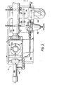
- the laser beam combiner 14 of Figure I is shown affixed to a mounting plate 400 mounted to the front, or exit end 13 of the laser generator unit II.
- the beam combiner 14 is of welded construction, having a baseplate 401 extending past side flanges 402, 403 secured by a cap screw 404.
- the baseplate 401 has a central horizontal hole 405 with clearance around the flange 406 of a laser entry tube 407, flange-mounted with screws 408 against the baseplate 400.
- the tube 407 has a central bore 409 for the passage of the high power laser beam 12 emanating from the laser generator unit II.
- the beam combiner 14 has a side plate 410 extending parallel to the laser beam 12, and an end plate 41 is aligned at 90° to the side plate 410.
- the end plate 411 has a threaded collar 412 secured thereto, sealed with an 0-ring 413, and the first light pipe 15 is threadably received in the collar 412.
- the side plate 410 has a hole 414 and spot face 415 covered by a transparent window 416 which is gasketed and held in position with buttonhead screws 417.
- a relatively low-power laser generator unit 418 - for example, a helium neon (HeHe) laser, which emits a red visible light beam - is mounted at 90° to the side plate 410 on a mounting bracket 419 fastened to the mounting plate 400.
- HeHe helium neon
- the laser unit 418 is aligned so that the incoming beam 420 will form a right triangle with the axis 421 of the light pipe 15, In order to do so, a base angle alpha is selected and the apex angle delta would then be 90° minus alpha.
- a reflecting mirror 422 is positioned at the base corner 423 of the triangle, normal to a line 424 bisecting angle alpha. The mirror 422 is held against the end of a positioning plug 425 by a retaining cap 426 threadably received on the plug 425.
- the positioning plug 425 has a pilot diameter 427 received in a close-fitting bore 428 in a thick, angled side wall 429 of the box 14, and a flange 430 is recieved against a fitting washer 431 to adjustably position the mirror 423.
- the pilot 427 is sealed with a 0-ring 432, and the plug 425 is held in position by cap screws 433 received through the flange 430.
- the end 434 of the laser entry tube 407 is machined flat, normal to a line 435 bisecting angle delta, and a shallow counterbore 436 in the surface 434 receives a reflecting mirror 437 which is retained by a retaining ring 438 and screws 439.
- the mirror 437 is made of a material such as gallium arsenide (GaAs), or zinc selenide (ZnSe), which is transparent to the working (C0 2 ) beam, but at least partially reflective to the alignment (HeNe) beam - due to the difference in wavelength of the two beams.
- a tooling plug 440 is inserted to a close-fitting bore 441 in the end plate 411 of the box 14.
- the plug 440 has a knurled outer diameter and has a small centered aperture 442 and a counter-drilled clearance hole 443.
- This beam 420 is utilised for aligning the various mirrors on the robot 10, since the higher-power main loser beam 12 is invisible to the eye.
- the tooling plug 440 is removed, and the low-power laser unit 418 may, optionally, be turned off, or left on to track the larger-diameter, high-power beam 12.
- the entry box 14 has an additional side plate 444 enclosing the structure, having a welded circular flange 445 and a clearance hole 446 therethrough.
- a thin mounting plate 447 is gasketed and secured to the flange 445 by cap screws 448, and the mounting plate 447, in turn, support a vortex tube 449 by means of a threaded end 450 passing through the plate 447 and secured with a locknut 451.
- the vortex tube 449 is of the type available from the Vortec Company, Cincinnati, Ohio, wherein compressed air enters through a side inlet 452 at a first reference temperature. Through a vortex/spinning action, cold air will exit one tube end 450 and hot air will exit the other end 453.
- the cold air flows through the box 14 and down through the light pipe 15 to cool the various laser components and to slightly pressurise the system so as to prevent the entry of airborne contaminants from the atmosphere.
- the laser mounting bracket 419 also carries an air filter 454 and pressure regulator 455 tubed in series with the vortex tube 449 to regulate and clean the air received from an air pressure source (not shown).
- the device may be provided with cooling fluids other than air, for example, inert, low cost, gaseous nitrogen.
- a box like housing has a principal laser beam inlet aperture aligned with a laser outlet aperture to define a first laser beam path, and a second laser beam inlet aperture is located in the housing transversely to the first laser beam path.
- a laser mirror is mounted in said housing, said mirror having a reflective face obliquely intercepting the first laser beam path and the face is angled with respect to the second laser inlet aperture to define a second non-linear laser beam path comprising a line of incidence and a line of reflection with respect to the laser mirror, the line of reflection being colinear with at least a portion of the first laser beam path through the laser outlet aperture.
- a principal losing beam for example a C0 2 laser beam, is aligned with the first laser beam path through the housing, and a secondary, low-power laser beam, in the visible spectrum, is alinged with the second laser beam path to provide a reference for aligning the light pipe distribution system and accompanying reflectng.mirrors.
Landscapes
- Physics & Mathematics (AREA)
- Optics & Photonics (AREA)
- Engineering & Computer Science (AREA)
- Plasma & Fusion (AREA)
- Mechanical Engineering (AREA)
- General Physics & Mathematics (AREA)
- Robotics (AREA)
- Manufacturing & Machinery (AREA)
- Lasers (AREA)
- Laser Beam Processing (AREA)
- Mounting And Adjusting Of Optical Elements (AREA)
Applications Claiming Priority (2)
| Application Number | Priority Date | Filing Date | Title |
|---|---|---|---|
| US06/840,238 US4722591A (en) | 1986-03-17 | 1986-03-17 | Laser beam combiner |
| US840238 | 1992-02-24 |
Publications (3)
| Publication Number | Publication Date |
|---|---|
| EP0245608A2 true EP0245608A2 (de) | 1987-11-19 |
| EP0245608A3 EP0245608A3 (en) | 1988-11-02 |
| EP0245608B1 EP0245608B1 (de) | 1991-11-06 |
Family
ID=25281809
Family Applications (1)
| Application Number | Title | Priority Date | Filing Date |
|---|---|---|---|
| EP87103695A Expired - Lifetime EP0245608B1 (de) | 1986-03-17 | 1987-03-13 | Vorrichtung zur Zusammenführung von Laserstrahlen |
Country Status (4)
| Country | Link |
|---|---|
| US (1) | US4722591A (de) |
| EP (1) | EP0245608B1 (de) |
| JP (1) | JPS62272576A (de) |
| DE (1) | DE3774324D1 (de) |
Cited By (1)
| Publication number | Priority date | Publication date | Assignee | Title |
|---|---|---|---|---|
| CN102403647A (zh) * | 2011-11-22 | 2012-04-04 | 无锡庆源激光科技有限公司 | 铝合金单元金腔谐振激光器 |
Families Citing this family (32)
| Publication number | Priority date | Publication date | Assignee | Title |
|---|---|---|---|---|
| US5048911A (en) * | 1988-11-15 | 1991-09-17 | Universiti Malaya | Coupling of multiple laser beams to a single optical fiber |
| US6266359B1 (en) | 1999-09-02 | 2001-07-24 | Alphamicron, Inc. | Splicing asymmetric reflective array for combining high power laser beams |
| US7361171B2 (en) * | 2003-05-20 | 2008-04-22 | Raydiance, Inc. | Man-portable optical ablation system |
| US20050035097A1 (en) * | 2003-08-11 | 2005-02-17 | Richard Stoltz | Altering the emission of an ablation beam for safety or control |
| US9022037B2 (en) * | 2003-08-11 | 2015-05-05 | Raydiance, Inc. | Laser ablation method and apparatus having a feedback loop and control unit |
| US20050038487A1 (en) * | 2003-08-11 | 2005-02-17 | Richard Stoltz | Controlling pulse energy of an optical amplifier by controlling pump diode current |
| US8173929B1 (en) | 2003-08-11 | 2012-05-08 | Raydiance, Inc. | Methods and systems for trimming circuits |
| US7115514B2 (en) * | 2003-10-02 | 2006-10-03 | Raydiance, Inc. | Semiconductor manufacturing using optical ablation |
| US7143769B2 (en) * | 2003-08-11 | 2006-12-05 | Richard Stoltz | Controlling pulse energy of an optical amplifier by controlling pump diode current |
| US20050065502A1 (en) * | 2003-08-11 | 2005-03-24 | Richard Stoltz | Enabling or blocking the emission of an ablation beam based on color of target |
| US8921733B2 (en) | 2003-08-11 | 2014-12-30 | Raydiance, Inc. | Methods and systems for trimming circuits |
| US7413847B2 (en) * | 2004-02-09 | 2008-08-19 | Raydiance, Inc. | Semiconductor-type processing for solid-state lasers |
| US8135050B1 (en) | 2005-07-19 | 2012-03-13 | Raydiance, Inc. | Automated polarization correction |
| US7245419B2 (en) * | 2005-09-22 | 2007-07-17 | Raydiance, Inc. | Wavelength-stabilized pump diodes for pumping gain media in an ultrashort pulsed laser system |
| US7308171B2 (en) * | 2005-11-16 | 2007-12-11 | Raydiance, Inc. | Method and apparatus for optical isolation in high power fiber-optic systems |
| US7436866B2 (en) | 2005-11-30 | 2008-10-14 | Raydiance, Inc. | Combination optical isolator and pulse compressor |
| US8232687B2 (en) | 2006-04-26 | 2012-07-31 | Raydiance, Inc. | Intelligent laser interlock system |
| US8189971B1 (en) | 2006-01-23 | 2012-05-29 | Raydiance, Inc. | Dispersion compensation in a chirped pulse amplification system |
| US7444049B1 (en) * | 2006-01-23 | 2008-10-28 | Raydiance, Inc. | Pulse stretcher and compressor including a multi-pass Bragg grating |
| US7822347B1 (en) | 2006-03-28 | 2010-10-26 | Raydiance, Inc. | Active tuning of temporal dispersion in an ultrashort pulse laser system |
| US8432943B2 (en) | 2007-02-22 | 2013-04-30 | The Boeing Company | Monolithic fiber laser beam combiner |
| JP2009006350A (ja) * | 2007-06-27 | 2009-01-15 | Sony Corp | レーザ加工装置とその加工方法、デブリ回収機構とその回収方法、並びに表示パネルの製造方法 |
| US8975572B2 (en) | 2008-04-04 | 2015-03-10 | Cvi Laser, Llc | Compact, thermally stable fiber-optic array mountable to flow cell |
| US9413130B2 (en) | 2012-12-12 | 2016-08-09 | Cvi Laser, Llc | Optical systems |
| US7903706B2 (en) * | 2008-04-04 | 2011-03-08 | O'shaughnessy John | Compact, thermally stable multi-laser engine |
| US10114213B2 (en) | 2008-04-04 | 2018-10-30 | Cvi Laser, Llc | Laser systems and optical devices for manipulating laser beams |
| US20090289382A1 (en) * | 2008-05-22 | 2009-11-26 | Raydiance, Inc. | System and method for modifying characteristics of a contact lens utilizing an ultra-short pulsed laser |
| US8125704B2 (en) * | 2008-08-18 | 2012-02-28 | Raydiance, Inc. | Systems and methods for controlling a pulsed laser by combining laser signals |
| US8554037B2 (en) | 2010-09-30 | 2013-10-08 | Raydiance, Inc. | Hybrid waveguide device in powerful laser systems |
| US11378808B2 (en) | 2018-07-18 | 2022-07-05 | Idex Health & Science Llc | Laser systems and optical devices for laser beam shaping |
| US12292566B2 (en) | 2020-07-31 | 2025-05-06 | Idex Health & Science Llc | Laser systems and optical devices for laser beam shaping |
| US12270703B2 (en) | 2022-04-28 | 2025-04-08 | Idex Health & Science Llc | Illumination systems and optical devices for laser beam shaping |
Family Cites Families (3)
| Publication number | Priority date | Publication date | Assignee | Title |
|---|---|---|---|---|
| GB2074343B (en) * | 1980-04-18 | 1984-01-25 | Inst Of Ophthalmology | Laser ophthalmic surgery apparatus |
| US4402574A (en) * | 1981-04-20 | 1983-09-06 | Weyerhaeuser Company | Method and apparatus for refracting a laser beam |
| US4532400A (en) * | 1982-10-01 | 1985-07-30 | Nippon Infrared Industries Co., Ltd. | Laser irradiating apparatus |
-
1986
- 1986-03-17 US US06/840,238 patent/US4722591A/en not_active Expired - Fee Related
-
1987
- 1987-03-13 DE DE8787103695T patent/DE3774324D1/de not_active Expired - Fee Related
- 1987-03-13 EP EP87103695A patent/EP0245608B1/de not_active Expired - Lifetime
- 1987-03-17 JP JP62062328A patent/JPS62272576A/ja active Pending
Cited By (2)
| Publication number | Priority date | Publication date | Assignee | Title |
|---|---|---|---|---|
| CN102403647A (zh) * | 2011-11-22 | 2012-04-04 | 无锡庆源激光科技有限公司 | 铝合金单元金腔谐振激光器 |
| CN102403647B (zh) * | 2011-11-22 | 2013-01-30 | 无锡庆源激光科技有限公司 | 铝合金单元金腔谐振激光器 |
Also Published As
| Publication number | Publication date |
|---|---|
| EP0245608A3 (en) | 1988-11-02 |
| JPS62272576A (ja) | 1987-11-26 |
| EP0245608B1 (de) | 1991-11-06 |
| DE3774324D1 (de) | 1991-12-12 |
| US4722591A (en) | 1988-02-02 |
Similar Documents
| Publication | Publication Date | Title |
|---|---|---|
| EP0245608B1 (de) | Vorrichtung zur Zusammenführung von Laserstrahlen | |
| JP2863872B2 (ja) | 動的レーザ標印 | |
| US5221823A (en) | Laser machining apparatus for welding and cutting | |
| US6531680B2 (en) | Cube corner laser beam retroreflector apparatus for a laser equipped machine tool | |
| US4575610A (en) | Laser shielding device | |
| JPS6156634B2 (de) | ||
| US5323269A (en) | System for transmitting and monitoring laser light and method for optical monitoring of a transmission path | |
| KR20040012719A (ko) | 레이저 기계가공에 있어서 초점 제어를 위한 방법 및 장치 | |
| ES2035642T3 (es) | Sistema y metodo de control de soldadura con laser. | |
| US20230057548A1 (en) | Laser cutting head for a machine tool | |
| EP0238307B1 (de) | Gelenk und Vorderarm für Roboterarm | |
| ATE51443T1 (de) | Auswaehlbar in einem buendel oder einer ebene projizierender laser und ausrichtsystem. | |
| CA1265206A (en) | Laser apparatus with a focus control unit | |
| CA2253976A1 (en) | Mirror failure detector for high power lasers | |
| EP0238309B1 (de) | Gelenk- und Unterarmgruppe eines Roboters | |
| EP4612767A1 (de) | Optischer verstärker | |
| US5991015A (en) | Beam monitoring assembly | |
| CA1189576A (en) | Laser cutting apparatus and method | |
| CN111958104A (zh) | 激光切割和雕刻标记一体机 | |
| SE9801590D0 (sv) | Anordning för att bestämma fokalpunktens läge i ett laserbearbetningssystem | |
| CN218361098U (zh) | 复合激光清洗头 | |
| US20240391026A1 (en) | Liquid Jet Laser Tool Utilizing An Off-Axis Laser Beam | |
| CN212384815U (zh) | 激光切割和雕刻标记一体机 | |
| ATE203946T1 (de) | Roboterhand für die bearbeitung von werkstücken mit laserstrahlung | |
| EP0241722A2 (de) | Schaltgerät für Laserbündel |
Legal Events
| Date | Code | Title | Description |
|---|---|---|---|
| PUAI | Public reference made under article 153(3) epc to a published international application that has entered the european phase |
Free format text: ORIGINAL CODE: 0009012 |
|
| AK | Designated contracting states |
Kind code of ref document: A2 Designated state(s): DE FR GB IT SE |
|
| ITCL | It: translation for ep claims filed |
Representative=s name: JACOBACCI CASETTA & PERANI S.P.A. |
|
| EL | Fr: translation of claims filed | ||
| PUAL | Search report despatched |
Free format text: ORIGINAL CODE: 0009013 |
|
| AK | Designated contracting states |
Kind code of ref document: A3 Designated state(s): DE FR GB IT SE |
|
| 17P | Request for examination filed |
Effective date: 19890116 |
|
| 17Q | First examination report despatched |
Effective date: 19900625 |
|
| GRAA | (expected) grant |
Free format text: ORIGINAL CODE: 0009210 |
|
| AK | Designated contracting states |
Kind code of ref document: B1 Designated state(s): DE FR GB IT SE |
|
| ITF | It: translation for a ep patent filed | ||
| REF | Corresponds to: |
Ref document number: 3774324 Country of ref document: DE Date of ref document: 19911212 |
|
| ET | Fr: translation filed | ||
| PLBE | No opposition filed within time limit |
Free format text: ORIGINAL CODE: 0009261 |
|
| STAA | Information on the status of an ep patent application or granted ep patent |
Free format text: STATUS: NO OPPOSITION FILED WITHIN TIME LIMIT |
|
| 26N | No opposition filed | ||
| PGFP | Annual fee paid to national office [announced via postgrant information from national office to epo] |
Ref country code: GB Payment date: 19940303 Year of fee payment: 8 |
|
| PGFP | Annual fee paid to national office [announced via postgrant information from national office to epo] |
Ref country code: FR Payment date: 19940310 Year of fee payment: 8 Ref country code: DE Payment date: 19940310 Year of fee payment: 8 |
|
| PGFP | Annual fee paid to national office [announced via postgrant information from national office to epo] |
Ref country code: SE Payment date: 19940316 Year of fee payment: 8 |
|
| EAL | Se: european patent in force in sweden |
Ref document number: 87103695.0 |
|
| PG25 | Lapsed in a contracting state [announced via postgrant information from national office to epo] |
Ref country code: GB Effective date: 19950313 |
|
| PG25 | Lapsed in a contracting state [announced via postgrant information from national office to epo] |
Ref country code: SE Effective date: 19950314 |
|
| GBPC | Gb: european patent ceased through non-payment of renewal fee |
Effective date: 19950313 |
|
| PG25 | Lapsed in a contracting state [announced via postgrant information from national office to epo] |
Ref country code: FR Free format text: LAPSE BECAUSE OF NON-PAYMENT OF DUE FEES Effective date: 19951130 |
|
| PG25 | Lapsed in a contracting state [announced via postgrant information from national office to epo] |
Ref country code: DE Effective date: 19951201 |
|
| EUG | Se: european patent has lapsed |
Ref document number: 87103695.0 |
|
| REG | Reference to a national code |
Ref country code: FR Ref legal event code: ST |
|
| PG25 | Lapsed in a contracting state [announced via postgrant information from national office to epo] |
Ref country code: IT Free format text: LAPSE BECAUSE OF NON-PAYMENT OF DUE FEES;WARNING: LAPSES OF ITALIAN PATENTS WITH EFFECTIVE DATE BEFORE 2007 MAY HAVE OCCURRED AT ANY TIME BEFORE 2007. THE CORRECT EFFECTIVE DATE MAY BE DIFFERENT FROM THE ONE RECORDED. Effective date: 20050313 |