EP0245666A2 - Dreh- und Kipptisch - Google Patents
Dreh- und Kipptisch Download PDFInfo
- Publication number
- EP0245666A2 EP0245666A2 EP87105486A EP87105486A EP0245666A2 EP 0245666 A2 EP0245666 A2 EP 0245666A2 EP 87105486 A EP87105486 A EP 87105486A EP 87105486 A EP87105486 A EP 87105486A EP 0245666 A2 EP0245666 A2 EP 0245666A2
- Authority
- EP
- European Patent Office
- Prior art keywords
- vehicle
- ramp
- horizontal
- platform
- rotating
- Prior art date
- Legal status (The legal status is an assumption and is not a legal conclusion. Google has not performed a legal analysis and makes no representation as to the accuracy of the status listed.)
- Granted
Links
Images


Classifications
-
- F—MECHANICAL ENGINEERING; LIGHTING; HEATING; WEAPONS; BLASTING
- F41—WEAPONS
- F41A—FUNCTIONAL FEATURES OR DETAILS COMMON TO BOTH SMALLARMS AND ORDNANCE, e.g. CANNONS; MOUNTINGS FOR SMALLARMS OR ORDNANCE
- F41A23/00—Gun mountings, e.g. on vehicles; Disposition of guns on vehicles
- F41A23/26—Mountings for transport only; Loading or unloading arrangements for guns for use with carrier vehicles
-
- B—PERFORMING OPERATIONS; TRANSPORTING
- B66—HOISTING; LIFTING; HAULING
- B66F—HOISTING, LIFTING, HAULING OR PUSHING, NOT OTHERWISE PROVIDED FOR, e.g. DEVICES WHICH APPLY A LIFTING OR PUSHING FORCE DIRECTLY TO THE SURFACE OF A LOAD
- B66F7/00—Lifting frames, e.g. for lifting vehicles; Platform lifts
- B66F7/22—Lifting frames, e.g. for lifting vehicles; Platform lifts with tiltable platforms
-
- B—PERFORMING OPERATIONS; TRANSPORTING
- B66—HOISTING; LIFTING; HAULING
- B66F—HOISTING, LIFTING, HAULING OR PUSHING, NOT OTHERWISE PROVIDED FOR, e.g. DEVICES WHICH APPLY A LIFTING OR PUSHING FORCE DIRECTLY TO THE SURFACE OF A LOAD
- B66F7/00—Lifting frames, e.g. for lifting vehicles; Platform lifts
- B66F7/24—Lifting frames, e.g. for lifting vehicles; Platform lifts for raising or lowering vehicles by their own power
- B66F7/243—Ramps
Definitions
- the present invention relates to a turn tilt table on a self propelled vehicle, and more particularly relates to such a turn tilt table for rotating objects such as a military vehicle through 360° while tilting the military vehicle between a horizontal position and 45° from the horizontal.
- the turn tilt table of the present invention is intended to support a test vehicle (hereinafter termed a military vehicle) weighing up to about 70 tons, and to rotate the table and military vehicle to any of a plurality of positions within 360°, and to tilt the table and military vehicle thereon between a horizontal position and a position that is tilted between 0° and 45° from the horizontal.
- the turn tilt table with the military vehicle rigidly secured to the table is positioned in a test area including a control tower from which a line of sight to the vehicle may be taken which line of sight includes a radar beam or other beam directed at the test vehicle.
- the military vehicle is rotated and tilted to present all detectable upright and top surfaces to the beam for the purpose of determining which surface finish or configuration is best to prevent an enemy from detecting the vehicle during combat by radar or the like, or determining the vehicle radar signatures.
- the turn tilt table vehicle is moved to different locations at the test area so that the effectiveness of the surface finish can be determined at different horizontal and vertical angles from the tower and also at ranges up to at least three kilometers. If the military vehicle being tested is relatively light, such as a one-half ton vehicle or an Mll3 personnel carrier, the turn tilt table vehicle may be driven to different locations in the test area while carrying the military vehicle at a time when the turn tilt table is in a horizontal position.
- the turn tilt vehicle may carry the military vehicle to different locations in the test area provided the vehicle supporting surface has a density sufficient to support the load.
- Towable ramps are also provided for connection to the turn tilt table thereby enabling the military vehicle to be driven up the ramps onto the turn tilt table.
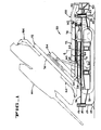
- the turn tilt table vehicle 20 (Figs. l, 2, 4 and 5) of the present invention comprises a pair of tread members or tracks 22,24 each having hydraulic motors 26,28 (Fig. 2) for driving the tracks.
- the tracks are connected to a leveling frame 36 by tubular connectors 34 which may be removed from the leveling frame 36 to reduce the overall width of the leveling frame when the vehicle is broken down into several components for shipment by truck or by rail to different locations.
- the leveling frame 36 is rigidly connected to outrigger beams 40,42.
- Hydraulically actuated jack cylinders 46 having pontoons 48 on the lower ends of piston rods 49 are mounted on the ends of the outrigger beams 40,42 for leveling the frame 36 and components supported thereon when in testing position on the test area.
- An engine 50 and hydraulic pumps 52 are supported on the leveling frame 36 to provide hydraulic power to the track motors 26,28; to the leveling jack cylinders 46 and to other hydraulic components to be described hereinafter.
- a tilting frame 54 is pivotally attached to lugs 56 on the leveling frame 36 by pins 58.
- the tilting frame is pivoted between a horizontal position and a tilted position of up to about 45° by a pair of hydraulic tilt cylinders 60 that are pivotally connected between the leveling frame 36 and the tilting frame 54 as best shown in Figure l.
- the tilting frame 54 supports a large diameter turntable bearing 64 having an upper rotatable portion 66 with gear teeth on its outer periphery which engage a pinion gear 68 (Fig. l) driven by a hydraulic motor and reducer 70.
- a pinion gear 68 Fig. l
- a rotating platform 72 (Figs. l-3) is rigidly secured to the rotatable portion 66 of the turntable bearing 64.
- the rotating platform 72 includes a track or wheel engaging bed 74 upon which the military vehicle MV to be tested is supported.
- the bed 74 is secured to a plurality of longitudinally extending beams (not shown) and a plurality of transverse beams 76 (Fig. l) which support the track or wheel engaging bed 74 upon the upper rotatable portion 66 of the turntable bearing 64.
- an operator station 80 is provided at the rear of the vehicle 20.
- the operator station includes framework 82 defining an operator's box 84 having an opening on its left side to permit an operator to enter and exit the box.
- the box 84 is pivotally supported on the rear outrigger beam 42 by a pivot pin 86.
- a latching rod 88 is removed from the lugs 90,92 on the outrigger beam 42 and the box 84 allowing the box to be pivoted to the phantom line position in Figure 2 thus simplifying the break down and transportation procedure.
- Conventional engine gauges, switches, and controls include; an ignition/starter button, a throttle lever, travel control and emergency shutdown controls mounted at the operator's station 80.
- Two live-dead switches are provided at the operator's station 80 with the first live-dead switch providing and denying power to hydraulic functions, i.e., swing, tilt, and outrigger jack controls.
- the second live-dead switch provides or denies power to the travel circuit thus insuring that the vehicle cannot travel during tests or when improperly positioned.
- a two section towable mobile loading ramp l00 (Figs. 6-l3) is provided to permit the military vehicle MV being tested to drive up the ramp l00 onto the rotating platform 72 and be parked with the center of gravity of the military vehicle being substantially centered on the vertical axis of rotation A of the rotating platform 72 and tilting frame 54 when horizontal.
- Each section l00a,l00b of the ramp l00 is identical, and is in the form of a relatively narrow two wheel trailer which is independently towed to and connected in its operative position as indicated in Figures 9-l2. Accordingly, only the ramp section l00a will be described in detail.
- the ramp section l00a comprises an inclined portion l02 having a tongue l03 bolted on its lower end and connected to a towing vehicle l04 by a connector l06.
- the upper end of the inclined portion is rigidly connected to a generally horizontal portion l08.
- a pair of wheels l09 (Fig. l3) are journaled on an axle ll0, and the axle is rigidly secured to arms ll2 that are connected to the inclined portion l02 of the ramp l00a for pivotal movement about axis C.
- the arms ll2 are strengthened by diagonal members ll3.
- a hydraulic cylinder ll4 is pivotally connected between the axle ll0 and the inclined portion l02 and may be controlled to raise or lower the ramp section l00a relative to the ground.
- traction bars ll6 (Fig. 7) and angle guide rails ll8 are welded to the inclined portion l02 and to the horizontal portion l08 of the ramp section l00a.
- a pair of legs l20 are welded to the inclined portion l02 of the ramp section l00a and cooperate with bumpers l22 welded to the axle ll0 to support the ramp section l00a on the axle when the hydraulic cylinder ll4 is fully retracted and is disconnected from its source of hydraulic fluid.
- the cylinder ll4 receives its hydraulic fluid through quick connect conduit l23, connected to the hydraulic circuit nearly centered between rear outrigger jacks 46.
- an associated vertical plate l24 (Figs. 8 and l4) is welded to and projects downwardly and rearwardly from the horizontal portion l08 and is guided between a pair of spaced V-shaped plates l26,l28 (Fig. 3).
- the spaced plates are welded to the rear wall of the rotating platform 72 and are reinforced by gussets l30,l32 having slots l34 therein.
- a hole l36 in the vertical plate l24 is aligned with the slots l34 when the ramp section l00a is in position to be attached to the rotating platform 72 and receives a pin l38 which is held in place by cotter pins or the like.
- a pair of bars l40 are welded to the rear end of the horizontal portion l08 of the ramp section l00a and operatively engage and are supported by a pair of hooks l42 on the rotating platform 72 to transfer the weight of a portion of the ramp section l00a and the military vehicle MV thereon to the rear end of the rotating platform 72 when the pin l38 connects the rotating platform to the ramp section l00a.
- a pair of pedestals l50 (Figs. 8 and l5) and shims l52 are bolted to the leveling frame 36.
- the upper end of each pedestal l50 removably receives a pin l53 to which a pair of links l54 are attached and held in place by cotter pins or the like.
- the upper ends of the links l54 are removably received on a second pin l56 which is slidably received in a collar l57 welded to the rotary platform 72 and is held in place by connectors such as cotter pins.
- a plurality of hold down arms l64 are bolted to the rotatable platform 72 in appropriate positions to supportively attach the particular type of vehicle being tested to the rotating platform 72.
- each hold down arm l64 When handling the illustrated military vehicle MV, each hold down arm l64 includes a sturdy box beam body l65 bolted to the rotating platform 72 and has an upturned end portion l66. Vehicle connecting brackets l68,l70 are connected to lugs (not shown) on the vehicle MV as by pinning or bolting. The brackets l68,l70 and a required number of shims l72,l74 are then bolted to the upturned end portion l66 of the associated hold down arm l64. Secured in this way, the vehicle MV may be turned and tilted to a plurality of positions, including those positions illustrated in Figures l, 4 and 5.
- the hydraulic components for driving the tracks 22,24 are conventional in the art being the same as that used in Assignee's LS-7400A Crawler Hydraulic Excavator.
- a simplified hydraulic circuit 200 is provided to support the claims, and is illustrated in Figure l6 as providing means for operating the turn table vehicle 20. It will be understood that certain protective circuits, check valves, and other conventional hydraulic circuitry have been omitted from the illustrated hydraulic circuit for simplicity.
- the circuit 200 includes a pump P driven by the engine and gearcase 50 which directs high pressure hydraulic fluid through main conduit HP and returns the fluid to a tank T through low pressure conduit LP.
- a pilot operated relief valve 202 opens and returns the fluid to tank T in the event the pressure in line HP exceeds a predetermined pressure.
- a plurality of manually or electrically operated valves Vl-V8 are connected to the high pressure and low pressure conduits, and are returned to their illustrated neutral positions by spring 204.
- the track drive motors 26 and 28 are preferably hydrostatic motors driven by hydrostatic pumps controlled by an operator with conventional controls.
- the turntable motor 70 rotates the platform 72 in o ne direction when the valve Vl is shifted to its parallel passage position, and in the opposite direction when shifted to the cross passage position When the valve Vl is in its illustrated central position, the motor 70 is hydraulically locked in fixed position.
- the four hydraulic jacks 46 are independently raised when valves V2-V5 are independently moved to the parallel passage position, and are lowered when the associated valves V2-V5 are moved to the cross passage position.
- the tilt cylinders 60 are raised when the valve V6 is moved to the parallel passage position and are lowered when the valve V6 is moved to the cross passage position.
- the two ramp cylinders ll4 for the two ramps l00 are independently retraated when the associated valves V7,V8 are in their parallel passage position, and are independently extended when the valves V7,V8 are moved to the cross passage position.
- a control tower 206 (Fig. l7) is placed in a test area 208 within which the turn tilt table vehicle 20, with a test object such as the military vehicle MV secured thereto, is driven to a plurality of different test locations.
- a radar beam 2l0 or the like is directed from the tower 206 at the test vehicle MV when in said plurality of locations to determine vehicle radar signatures or the like.
- the test vehicle may be spaced 3 kilometers away from the tower 206 or at any desired position closer to the tower. While at each test position the test vehicle MV may be tilted to any position between horizontal and the 45° position, and may be rotated to any desired position within the 360° range of rotation.
- a shield 2l4 may be placed between the tower and a major portion of the turn tilt table vehicle 20 thus exposing only the military vehicle to the beam.
- the self propelled turn tilt table vehicle of the present invention is capable of driving to different locations and supporting an article to be tested such as a military vehicle weighing up to about 70 tons.
- a loading ramp may be connected to the turn tilt table vehicle for allowing a test vehicle to be driven onto or off the turn tilt table vehicle.
- the turn tilt vehicle is capable of tilting a rotating platform to which the test vehicle is rigidly secured to anywhere between a horizontal position and a position tilting the vehicle up to about 45° from horizontal. While in the horizontal position, or any one of the tilted positions, the rotating platform and the test article or vehicle attached thereto may be rotated through 360° to test the surface finish of the article or vehicle for determining vehicle radar signatures or the like.
Landscapes
- Engineering & Computer Science (AREA)
- Life Sciences & Earth Sciences (AREA)
- Geology (AREA)
- Mechanical Engineering (AREA)
- Structural Engineering (AREA)
- General Engineering & Computer Science (AREA)
- Vehicle Cleaning, Maintenance, Repair, Refitting, And Outriggers (AREA)
- Geophysics And Detection Of Objects (AREA)
- Handcart (AREA)
Applications Claiming Priority (2)
| Application Number | Priority Date | Filing Date | Title |
|---|---|---|---|
| US851762 | 1986-04-14 | ||
| US06/851,762 US4796029A (en) | 1986-04-14 | 1986-04-14 | Turn tilt table |
Publications (3)
| Publication Number | Publication Date |
|---|---|
| EP0245666A2 true EP0245666A2 (de) | 1987-11-19 |
| EP0245666A3 EP0245666A3 (en) | 1990-01-24 |
| EP0245666B1 EP0245666B1 (de) | 1992-07-08 |
Family
ID=25311619
Family Applications (1)
| Application Number | Title | Priority Date | Filing Date |
|---|---|---|---|
| EP87105486A Expired EP0245666B1 (de) | 1986-04-14 | 1987-04-14 | Dreh- und Kipptisch |
Country Status (6)
| Country | Link |
|---|---|
| US (1) | US4796029A (de) |
| EP (1) | EP0245666B1 (de) |
| CA (1) | CA1303601C (de) |
| DE (1) | DE3780209T2 (de) |
| ES (1) | ES2033253T3 (de) |
| IL (2) | IL95573A0 (de) |
Cited By (9)
| Publication number | Priority date | Publication date | Assignee | Title |
|---|---|---|---|---|
| WO1993004974A1 (en) * | 1991-09-12 | 1993-03-18 | Isabella Domenica Marziale | A robotised rotoacrobatic exhibitor for operative technical or commercial advertising purposes, to show locomotion and generally transportation means |
| FR2685911A1 (fr) * | 1992-01-03 | 1993-07-09 | Bretagne Concept Sarl | Dispositif de manipulation d'articles encombrants et lourds se presentant sous la forme de rouleaux. |
| WO2002066362A3 (de) * | 2001-02-21 | 2002-11-21 | Siemens Ag | Kraftfahrzeug-prüfstand mit einer kippvorrichtung |
| FR2929919A1 (fr) * | 2008-04-14 | 2009-10-16 | Nexter Systems Sa | Procede de retournement d'une structure et outillage associe a un tel procede. |
| CN104444939A (zh) * | 2014-12-26 | 2015-03-25 | 徐学翠 | 一种大型卡车检查系统 |
| CN112268542A (zh) * | 2020-10-23 | 2021-01-26 | 湖南砼联科技有限责任公司 | 一种风电机组塔筒倾斜角的检测方法及测量装置 |
| CN113375500A (zh) * | 2020-03-10 | 2021-09-10 | 中国科学院沈阳自动化研究所 | 一种军工装备翻转测试装置 |
| CN115947279A (zh) * | 2022-12-03 | 2023-04-11 | 北京航天发射技术研究所 | 起竖装置 |
| EP4186811A1 (de) * | 2021-11-29 | 2023-05-31 | Transports Publics Neuchâtelois SA | Device for handling a railway vehicle coupling and associated method |
Families Citing this family (14)
| Publication number | Priority date | Publication date | Assignee | Title |
|---|---|---|---|---|
| US5096365A (en) * | 1990-10-24 | 1992-03-17 | Shoals American Industries, Inc. | Apparatus and method for lifting, rotating, and stacking trailer chassis |
| US5524188A (en) * | 1993-03-01 | 1996-06-04 | Halpern Software, Inc. | Viewing three dimensional objects by rotational wobble about multiple axes |
| US5400720A (en) * | 1993-04-07 | 1995-03-28 | Vestil Manufacturing Company | Lift and tilt table |
| US5681033A (en) * | 1996-02-01 | 1997-10-28 | Northrop Grumman Corporation | Workpiece pick-up jig and positioning tool |
| US20040120799A1 (en) * | 2002-12-20 | 2004-06-24 | Kessler Jack C. | Trailer with rotating bed |
| NL1022479C1 (nl) * | 2003-01-23 | 2003-02-25 | Gerhardus Henricus Mari Albers | Presentatietafel. |
| US20050173601A1 (en) * | 2003-10-28 | 2005-08-11 | Hestand Larry D. | System for displaying a motor vehicle, apparatus and related methods |
| US7427183B2 (en) * | 2005-02-18 | 2008-09-23 | Gary L. Stabeno | Reversible transport trailer |
| CN103354911A (zh) * | 2010-08-16 | 2013-10-16 | 地面探测器有限公司 | 作业区域监视器 |
| CA2810606A1 (en) * | 2012-04-10 | 2013-10-10 | CAA South Central Ontario | Method and kit for providing a training course for operating a towing device |
| CN103630163B (zh) * | 2013-12-12 | 2015-10-21 | 深圳出入境检验检疫局玩具检测技术中心 | 玩具倾翻测试仪及其测试方法 |
| US10472216B2 (en) * | 2015-07-17 | 2019-11-12 | Arnco Solutions | Railcar vibrator lifter |
| ITUB20155900A1 (it) * | 2015-11-25 | 2017-05-25 | Magni Telescopic Handlers S R L | Piattaforma aerea semovente |
| SE545226C2 (en) * | 2020-02-17 | 2023-05-30 | Bae Systems Haegglunds Ab | A military vehicle comprising an aiming device and an aiming operation arrangement for a vehicle operator to operate the aiming device |
Family Cites Families (15)
| Publication number | Priority date | Publication date | Assignee | Title |
|---|---|---|---|---|
| US1534364A (en) * | 1922-10-16 | 1925-04-21 | Francisco Fabricio Y Diaz | Apparatus for raising vehicles |
| US1973803A (en) * | 1934-04-27 | 1934-09-18 | John A Frauen | Elevating apparatus |
| US2572776A (en) * | 1948-08-03 | 1951-10-23 | Harry T Smith | Subgrade and shouldering machine |
| US2884242A (en) * | 1955-09-20 | 1959-04-28 | British Oxygen Co Ltd | Welding positioners |
| US3156108A (en) * | 1959-10-13 | 1964-11-10 | North American Aviation Inc | Missile attitude positioner |
| US3228546A (en) * | 1963-11-15 | 1966-01-11 | Harry J Bunch | Tractor-trailer hitch |
| NL6715907A (de) * | 1967-11-23 | 1969-05-28 | ||
| US3536214A (en) * | 1968-12-11 | 1970-10-27 | Robert P Sorg | Turntable trailer apparatus |
| US3670903A (en) * | 1969-12-03 | 1972-06-20 | Otis L Hamilton | Skid inverting device |
| US3931895A (en) * | 1974-11-01 | 1976-01-13 | Samuel Grimaldo | Collapsible trailer hoist |
| DE2634937C2 (de) * | 1976-08-04 | 1978-11-09 | Kloeckner-Werke Ag, 4100 Duisburg | Bettungsplattform zur Erprobung von Waffen und Munition |
| US4134501A (en) * | 1977-05-10 | 1979-01-16 | Tune Shearer E | Tilting service lift for automotive equipment with folding lift unit |
| US4132323A (en) * | 1977-10-25 | 1979-01-02 | Simmons Lovel R | Combination tank transporter and general cargo trailer |
| IT7868297A0 (it) * | 1978-06-06 | 1978-06-06 | Migliorati Pier Ippolito | Banco ponte auto |
| DE3260515D1 (en) * | 1981-03-06 | 1984-09-13 | Voest Alpine Ag | Test stand for high-trajectory firearms |
-
1986
- 1986-04-14 US US06/851,762 patent/US4796029A/en not_active Expired - Fee Related
-
1987
- 1987-03-17 CA CA000532205A patent/CA1303601C/en not_active Expired - Lifetime
- 1987-03-25 IL IL9095573A patent/IL95573A0/xx not_active IP Right Cessation
- 1987-03-25 IL IL8782012A patent/IL82012A/xx unknown
- 1987-04-14 EP EP87105486A patent/EP0245666B1/de not_active Expired
- 1987-04-14 DE DE8787105486T patent/DE3780209T2/de not_active Expired - Lifetime
- 1987-04-14 ES ES198787105486T patent/ES2033253T3/es not_active Expired - Lifetime
Cited By (14)
| Publication number | Priority date | Publication date | Assignee | Title |
|---|---|---|---|---|
| WO1993004974A1 (en) * | 1991-09-12 | 1993-03-18 | Isabella Domenica Marziale | A robotised rotoacrobatic exhibitor for operative technical or commercial advertising purposes, to show locomotion and generally transportation means |
| FR2685911A1 (fr) * | 1992-01-03 | 1993-07-09 | Bretagne Concept Sarl | Dispositif de manipulation d'articles encombrants et lourds se presentant sous la forme de rouleaux. |
| WO2002066362A3 (de) * | 2001-02-21 | 2002-11-21 | Siemens Ag | Kraftfahrzeug-prüfstand mit einer kippvorrichtung |
| US7316158B2 (en) | 2001-02-21 | 2008-01-08 | Siemens Aktiengesellschaft | Test stand with tipping device for motor vehicles |
| US8177472B2 (en) | 2008-04-14 | 2012-05-15 | Nexter Systems | Process to invert a structure and the associated tooling to such a process |
| EP2110297A1 (de) * | 2008-04-14 | 2009-10-21 | NEXTER Systems | Strukturschwenk-Verfahren und -Vorrichtung |
| FR2929919A1 (fr) * | 2008-04-14 | 2009-10-16 | Nexter Systems Sa | Procede de retournement d'une structure et outillage associe a un tel procede. |
| CN104444939A (zh) * | 2014-12-26 | 2015-03-25 | 徐学翠 | 一种大型卡车检查系统 |
| CN113375500A (zh) * | 2020-03-10 | 2021-09-10 | 中国科学院沈阳自动化研究所 | 一种军工装备翻转测试装置 |
| CN113375500B (zh) * | 2020-03-10 | 2022-06-28 | 中国科学院沈阳自动化研究所 | 一种军工装备翻转测试装置 |
| CN112268542A (zh) * | 2020-10-23 | 2021-01-26 | 湖南砼联科技有限责任公司 | 一种风电机组塔筒倾斜角的检测方法及测量装置 |
| CN112268542B (zh) * | 2020-10-23 | 2022-11-08 | 湖南砼联科技有限责任公司 | 一种风电机组塔筒倾斜角的检测方法及测量装置 |
| EP4186811A1 (de) * | 2021-11-29 | 2023-05-31 | Transports Publics Neuchâtelois SA | Device for handling a railway vehicle coupling and associated method |
| CN115947279A (zh) * | 2022-12-03 | 2023-04-11 | 北京航天发射技术研究所 | 起竖装置 |
Also Published As
| Publication number | Publication date |
|---|---|
| DE3780209T2 (de) | 1992-12-24 |
| EP0245666B1 (de) | 1992-07-08 |
| IL82012A0 (en) | 1987-10-20 |
| IL82012A (en) | 1991-06-10 |
| CA1303601C (en) | 1992-06-16 |
| EP0245666A3 (en) | 1990-01-24 |
| DE3780209D1 (de) | 1992-08-13 |
| IL95573A0 (en) | 1991-06-30 |
| IL95573A (en) | 1991-06-10 |
| ES2033253T3 (es) | 1993-03-16 |
| US4796029A (en) | 1989-01-03 |
Similar Documents
| Publication | Publication Date | Title |
|---|---|---|
| EP0245666A2 (de) | Dreh- und Kipptisch | |
| US5529454A (en) | Transporting apparatus and method | |
| AU2001288248B2 (en) | Mobile aircraft launcher | |
| US4143781A (en) | Hoisting mechanism for straddle carrier spreader and straddle carrier steering system | |
| US5080541A (en) | Articulated car carrier convoy with individual carrying platforms capable of compound movements | |
| US3954193A (en) | Apparatus and method for transferring a crane boom assembly from a crane carrier to an independent transport vehicle | |
| US3784035A (en) | Vehicle mounted loading hoist | |
| US4660731A (en) | Telescopic crane for heavy loads | |
| US4111314A (en) | Transportable silo | |
| FI63546B (fi) | Transportfordon med en bakaot oeppen u-formad ram | |
| US3467268A (en) | Apparatus for handling and transport of heavy bulky containers | |
| CA2058042A1 (en) | Transport trailer structure for supporting canoes and other vehicles and loads, and methods of using such trailer structures | |
| US5562388A (en) | Vehicle for transporting an aircraft on the ground | |
| EP0153187B1 (de) | Bergungs- und Abschleppfahrzeug | |
| US3909057A (en) | Combination camper and boat trailer mechanism | |
| US5332345A (en) | Vehicle carrier | |
| US4830562A (en) | Apparatus for loading and unloading railroad gondola cars | |
| CA1302456C (en) | Convertible boat and vehicle trailer | |
| EP0132072A1 (de) | Kraftfahrzeugabschleppvorrichtung | |
| US4723886A (en) | Method and apparatus for loading and unloading railroad gondola cars | |
| JP2001122599A (ja) | 高所作業車 | |
| CA1199308A (en) | Carrying platform for receiving a goods van or container and provided with means for its adaptation to transport by road, rail and sea | |
| US20060104771A1 (en) | Portable device for inspection of vehicles | |
| US3449010A (en) | Load transporting vehicles | |
| US11597435B2 (en) | Drilling rig |
Legal Events
| Date | Code | Title | Description |
|---|---|---|---|
| PUAI | Public reference made under article 153(3) epc to a published international application that has entered the european phase |
Free format text: ORIGINAL CODE: 0009012 |
|
| AK | Designated contracting states |
Kind code of ref document: A2 Designated state(s): DE ES FR GB IT SE |
|
| 17P | Request for examination filed |
Effective date: 19880412 |
|
| PUAL | Search report despatched |
Free format text: ORIGINAL CODE: 0009013 |
|
| AK | Designated contracting states |
Kind code of ref document: A3 Designated state(s): DE ES FR GB IT SE |
|
| 17Q | First examination report despatched |
Effective date: 19910930 |
|
| ITF | It: translation for a ep patent filed | ||
| GRAA | (expected) grant |
Free format text: ORIGINAL CODE: 0009210 |
|
| AK | Designated contracting states |
Kind code of ref document: B1 Designated state(s): DE ES FR GB IT SE |
|
| REF | Corresponds to: |
Ref document number: 3780209 Country of ref document: DE Date of ref document: 19920813 |
|
| ET | Fr: translation filed | ||
| REG | Reference to a national code |
Ref country code: ES Ref legal event code: FG2A Ref document number: 2033253 Country of ref document: ES Kind code of ref document: T3 |
|
| PG25 | Lapsed in a contracting state [announced via postgrant information from national office to epo] |
Ref country code: GB Effective date: 19930414 |
|
| PG25 | Lapsed in a contracting state [announced via postgrant information from national office to epo] |
Ref country code: SE Effective date: 19930415 Ref country code: ES Free format text: LAPSE BECAUSE OF NON-PAYMENT OF DUE FEES Effective date: 19930415 |
|
| PLBE | No opposition filed within time limit |
Free format text: ORIGINAL CODE: 0009261 |
|
| STAA | Information on the status of an ep patent application or granted ep patent |
Free format text: STATUS: NO OPPOSITION FILED WITHIN TIME LIMIT |
|
| 26N | No opposition filed | ||
| GBPC | Gb: european patent ceased through non-payment of renewal fee |
Effective date: 19930414 |
|
| PG25 | Lapsed in a contracting state [announced via postgrant information from national office to epo] |
Ref country code: FR Effective date: 19931229 |
|
| PG25 | Lapsed in a contracting state [announced via postgrant information from national office to epo] |
Ref country code: DE Effective date: 19940101 |
|
| REG | Reference to a national code |
Ref country code: FR Ref legal event code: ST |
|
| EUG | Se: european patent has lapsed |
Ref document number: 87105486.2 Effective date: 19931110 |
|
| REG | Reference to a national code |
Ref country code: ES Ref legal event code: FD2A Effective date: 19990201 |
|
| PG25 | Lapsed in a contracting state [announced via postgrant information from national office to epo] |
Ref country code: IT Free format text: LAPSE BECAUSE OF NON-PAYMENT OF DUE FEES;WARNING: LAPSES OF ITALIAN PATENTS WITH EFFECTIVE DATE BEFORE 2007 MAY HAVE OCCURRED AT ANY TIME BEFORE 2007. THE CORRECT EFFECTIVE DATE MAY BE DIFFERENT FROM THE ONE RECORDED. Effective date: 20050414 |