EP0245720A2 - Transmission planétaire à quatre vitesses - Google Patents
Transmission planétaire à quatre vitesses Download PDFInfo
- Publication number
- EP0245720A2 EP0245720A2 EP87106332A EP87106332A EP0245720A2 EP 0245720 A2 EP0245720 A2 EP 0245720A2 EP 87106332 A EP87106332 A EP 87106332A EP 87106332 A EP87106332 A EP 87106332A EP 0245720 A2 EP0245720 A2 EP 0245720A2
- Authority
- EP
- European Patent Office
- Prior art keywords
- gear
- sun
- gears
- housing
- planetary gear
- Prior art date
- Legal status (The legal status is an assumption and is not a legal conclusion. Google has not performed a legal analysis and makes no representation as to the accuracy of the status listed.)
- Withdrawn
Links
- 230000008878 coupling Effects 0.000 claims description 8
- 238000010168 coupling process Methods 0.000 claims description 8
- 238000005859 coupling reaction Methods 0.000 claims description 8
- 238000006073 displacement reaction Methods 0.000 claims description 2
- 230000005540 biological transmission Effects 0.000 abstract description 21
- 238000010276 construction Methods 0.000 description 4
- 238000010586 diagram Methods 0.000 description 2
- 238000013519 translation Methods 0.000 description 2
- 230000014616 translation Effects 0.000 description 2
- 239000010720 hydraulic oil Substances 0.000 description 1
- 230000004048 modification Effects 0.000 description 1
- 238000012986 modification Methods 0.000 description 1
Images

Classifications
-
- F—MECHANICAL ENGINEERING; LIGHTING; HEATING; WEAPONS; BLASTING
- F16—ENGINEERING ELEMENTS AND UNITS; GENERAL MEASURES FOR PRODUCING AND MAINTAINING EFFECTIVE FUNCTIONING OF MACHINES OR INSTALLATIONS; THERMAL INSULATION IN GENERAL
- F16H—GEARING
- F16H3/00—Toothed gearings for conveying rotary motion with variable gear ratio or for reversing rotary motion
- F16H3/44—Toothed gearings for conveying rotary motion with variable gear ratio or for reversing rotary motion using gears having orbital motion
- F16H3/62—Gearings having three or more central gears
- F16H3/66—Gearings having three or more central gears composed of a number of gear trains without drive passing from one train to another
-
- F—MECHANICAL ENGINEERING; LIGHTING; HEATING; WEAPONS; BLASTING
- F16—ENGINEERING ELEMENTS AND UNITS; GENERAL MEASURES FOR PRODUCING AND MAINTAINING EFFECTIVE FUNCTIONING OF MACHINES OR INSTALLATIONS; THERMAL INSULATION IN GENERAL
- F16H—GEARING
- F16H2200/00—Transmissions for multiple ratios
- F16H2200/003—Transmissions for multiple ratios characterised by the number of forward speeds
- F16H2200/0043—Transmissions for multiple ratios characterised by the number of forward speeds the gear ratios comprising four forward speeds
Definitions
- the invention relates to a four-speed epicyclic gear with two axially successively arranged planetary gears, each of which has a gear part which can be connected to the housing or another gear part by means of clutches for shifting the gears.
- Such a four-speed epicyclic gearbox is known, for example, from Bussien: "Automobiltechnisches Handbuch", 18th edition, 1965, page 240, picture 18 and page 306, diagram 130.
- this known transmission has a hydrodynamic clutch which is connected between the two planetary gear sets. With its clutches, this transmission has a very large construction volume and therefore a space requirement that is no longer available in modern motor vehicles.
- the invention has for its object to improve the structure of such a transmission so that a high degree of efficiency is achieved with a compact design, so that such a transmission can also be used when there is little space available and still high power is transmitted have to. So it should be particularly suitable as a quadruple load switch splitter for commercial vehicles.
- the sun gears of both planetary gears can be connected either to the housing or the associated input shaft or output shaft, that the input shaft with the land of the first planetary gear set and the output shaft either with the ring gear or also with the land of is connected to the second planetary gear set and that the ring gear of the first planetary gear set is connected to the web in the first case and to the ring gear of the second planetary gear set in the second case.
- the sun gears of both planetary gears either with the housing or the assigned input or. Connecting the output shaft becomes a symmetrical structure possible of the gearbox, which can be used for a special compact structure.
- a preferred embodiment of the invention provides that the clutches are arranged axially in front of or behind the associated planetary gear set and the couplings connecting the sun gears to the shafts are each arranged within the couplings connecting the sun gears to the housing.
- the sun gears can then each be connected to a ring, on the outer and inner sides of which clutch plates are arranged, which interact with clutch plates fixed to the housing or with clutch plates attached to the associated shaft.
- This design of the transmission further advantageously offers the possibility that the clutches are provided with hydraulic pistons acting on the clutch plates in the axial direction. It is particularly advantageous if a hydraulic piston only acts on the clutch plates producing the connection between the sun gear and the housing, whereas the clutch plates producing the connection between the sun gear and the associated shaft are loaded by a spring. This arrangement can then be made such that the closing of the coupling that establishes the connection to the housing causes a displacement the clutch plates on the rim of the sun gear, by means of which the connection between the sun gear and the associated shaft is released against the force of the spring.
- the spring used here can advantageously be a plate spring.
- the last-described embodiment of the invention has the particular advantage that a hydraulic piston only has to be arranged in the fixed housing, so that no pistons have to be arranged in rotating gear or clutch parts and have to be supplied with a pressure medium.
- Another advantage is that even in the event of failure of the pressure medium required to shift the transmission, in particular a hydraulic system, the connection between the sun gears and the associated shafts producing clutches are closed, so that a defined connection via the transmission between the input and Output shaft is preserved.
- a translation is preferably selected here which still allows driving, so that a vehicle provided with such a transmission can reach a workshop under its own power.
- an input shaft 2 and an output shaft 3 are mounted coaxially to one another in a housing 1.
- Each of these two waves 2, 3 is assigned a planetary gear set.
- the planetary gear set associated with the input shaft 2 comprises a sun gear 4, planetary gears 5 and a ring gear 6.
- the planet gears 5 are mounted in a web 7 which is fastened to the end of the input shaft 2 and are located on the outside thereof facing the input shaft 2.
- the sun gear 4 is located on an essentially disk-shaped carrier 8, which adjoins the web 7 with the planet gears 5 to the outside.
- the planetary gear set associated with the output shaft 3 also includes a sun gear 11, planetary gears 12 and a ring gear 13.
- the ring gear 13 is located on the edge of a disk 14 which is arranged at the end of the output shaft 3 close to the web 7 attached to the end of the input shaft 2.
- the planet gears 12 are located on the outside of the disk 14 facing the output shaft 3 and are supported by a web 15 which is connected to the ring gear 6 of the planetary gear set assigned to the input shaft 2 by a connecting piece 16 encompassing the ring gear 13 of the other planetary gear set.
- the sun gear 11 is in turn attached to the inner edge of a disk-shaped carrier 17 which is arranged on the outside of the web 15.
- the sun gears 4 and 11 can optionally be connected to the input shaft 2 or output shaft 3 or the housing 1 by means of couplings.
- the clutches for the two sun gears 4 and 11 are constructed mirror-symmetrically, so that only the clutches assigned to one of these sun gears need to be described.
- the clutch arrangement which belongs to the planetary gear set which is assigned to the input shaft 2 is therefore described in detail below.
- the components of the clutch arrangement which are assigned to the planetary gear set of the output shaft 3 are provided with the same, but deleted reference numerals as the corresponding components of the clutch arrangement which belongs to the planetary gear set assigned to the input shaft 2.
- the disk-shaped carrier 8 of the sun gear 4 is provided on its outer edge with an outwardly extending ring 21, on the outer and inner sides of which non-rotatably but axially displaceably held clutch plates 22, 23 are arranged.
- the radially outer clutch plate 22 engages between two clutch plates 24, 25, which are also held in the housing 1 in the axial direction, but are non-rotatably.
- the piston 26 If the piston 26 is pressurized with a pressure medium, it moves against the friction clutch formed by the clutch plates 24, 22, 25 and clamps the clutch plate 22 connected to the sun gear 4 between the clutch plates 24, 25 connected to the housing, of which one on one stop ring fixed to the housing 28 system.
- the piston 26 is loaded by a plate spring 29 which is supported in the housing 1 and tends to return the piston 26 to a rest position in which the clutch connecting the sun gear 4 to the housing 1 is released when the chamber 27 behind the piston 26 is ventilated.
- the clutch plate 23 arranged on the inside of the ring 21 interacts with a clutch plate 31, which is mounted on the input shaft 2 in a rotationally fixed manner by means of an intermediate piece 32, but is displaceable in the axial direction of the shaft.
- a plate spring 33 is arranged, which strives to press the clutch plate 23 against the clutch plate 31, which is arranged on the input shaft 2 in a rotationally fixed manner, and against an abutment 34 which is rotatably mounted in the housing 1 and which is also provided with the collar 21 is connected in a rotationally fixed manner to the support 8 and is fixed in the axial direction with respect to the support by a stop ring 35.
- the plate spring 33 presses the clutch plate 23, which is connected to the sun gear 4 assigned to the input shaft 2, against the clutch plate 31 connected to the input shaft 2 and this clutch plate against the abutment, which is also connected to the sun wheel 4 in a rotationally fixed manner 34.
- a rotationally fixed connection between the sun gear 4 and the input shaft 2 is produced, which leads to a rigid connection between the sun gear 4 and the web 7 connected to the input shaft 2.
- the planet gears 5 are rotationally fixed, so that the ring gear 6 belonging to the planetary gear set associated with the input shaft together with the Input shaft 2 rotates.
- the clutch plate 31 ' which is non-rotatably connected to the output shaft 3, is firmly clamped between the abutment 34' and the clutch plate 23 ', which is connected to the sun gear 11 via the carrier 17 and is loaded by the plate spring 33'.
- the non-positive connection between the output shaft 3 and the sun gear 11 has the result that the sun gear 11 and the ring gear 13 connected to the output shaft 3 via the disk 14 have the same speed, so that the arranged between the sun gear 11 and the ring gear 13 Planet gears 12 can not perform a rotational movement. Accordingly, the web 15 carrying the planet gears 12 rotates at the same speed as the output shaft 3. Since the web 15 is connected via the connecting piece 16 to the ring gear 6 of the planetary gear set on the input side, there is a direct coupling between the input shaft 2 and the output shaft 3.
- the clutch plate 22 guided in the collar 21 simultaneously presses axially against the radially inner clutch plate 23 and lifts this clutch plate against the force of the plate spring 33 from the clutch plate 31 connected to the input shaft 2 via the intermediate piece 32 from, so that the connection of the sun gear 4 with the input shaft 2 is released and the sun gear is non-positively connected to the housing 1.
- the sun gear 4 is stationary, so that the planet gears 5 carried along by the web 7 from the input shaft 2 roll on the sun gear 4.
- This rotary movement is then transmitted to the ring gear 6, the speed of which now deviates from the speed of the input shaft 2 from the ratio of the number of teeth of the sun gear 4 and the ring gear 6.
- the sun gear 11 assigned to the output shaft 3 can be non-positively connected to the housing 1, while at the same time the previously existing connection to the output shaft 3 is released.
- the planet gears 12 driven by the rotating web 15 roll on the stationary sun gear 11, so that the ring gear 13 is set in rotation at a speed corresponding to the ratio of the number of teeth of the sun gear 11 and the ring gear 13 from the speed of the Web 15 deviates.
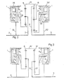
- F ig. 2 shows the construction of the transmission shown in FIG. 1 again schematically.
- the clutches K1, K3 located on the outside with respect to the rings 21, 21 'bring about a non-positive connection of the associated sun gear 4 and 11 to the housing 1 when the piston 26 and 26' is acted upon by a pressure medium. If, however, the pistons 26, 26 'are relieved, the clutches K2, K4, which are located radially on the inside with respect to the ring 21 and 21', are closed by the force of the plate spring 33 and 33 ', so that the sun gears 4, 11th are non-positively connected to the input shaft 2 and the output shaft 3 via the intermediate pieces 32, 32 '.
- Fig. 3 shows a variant of the epicyclic gearbox explained with reference to FIGS. 1 and 2, which only consists in the fact that in the case of the output-side planetary gear set with the output shaft 103 it is not the ring gear, but also the planetary gear as with the input-side planetary gear set the 12 'bearing web 15' is connected to the output shaft 3. Accordingly, the connecting piece 16 'also connects the ring gear 6 on the input side to the ring gear 13' on the output side. In this case, a sequence of four gears with the ratios 1.179 - 1.0 - 0.847 - 0.718 results with the same number of teeth.
Landscapes
- Engineering & Computer Science (AREA)
- General Engineering & Computer Science (AREA)
- Mechanical Engineering (AREA)
- Structure Of Transmissions (AREA)
- Retarders (AREA)
Applications Claiming Priority (2)
| Application Number | Priority Date | Filing Date | Title |
|---|---|---|---|
| DE19863615367 DE3615367A1 (de) | 1986-05-06 | 1986-05-06 | Viergang-umlaufgetriebe |
| DE3615367 | 1986-05-06 |
Publications (2)
| Publication Number | Publication Date |
|---|---|
| EP0245720A2 true EP0245720A2 (fr) | 1987-11-19 |
| EP0245720A3 EP0245720A3 (fr) | 1988-09-14 |
Family
ID=6300302
Family Applications (1)
| Application Number | Title | Priority Date | Filing Date |
|---|---|---|---|
| EP87106332A Withdrawn EP0245720A3 (fr) | 1986-05-06 | 1987-05-01 | Transmission planétaire à quatre vitesses |
Country Status (3)
| Country | Link |
|---|---|
| EP (1) | EP0245720A3 (fr) |
| JP (1) | JPS62270850A (fr) |
| DE (1) | DE3615367A1 (fr) |
Cited By (1)
| Publication number | Priority date | Publication date | Assignee | Title |
|---|---|---|---|---|
| EP0370298A1 (fr) * | 1988-11-08 | 1990-05-30 | Klöckner-Humboldt-Deutz Aktiengesellschaft | Changement de vitesse à rapports multiples pour un véhicule automobile |
Families Citing this family (3)
| Publication number | Priority date | Publication date | Assignee | Title |
|---|---|---|---|---|
| JP2785325B2 (ja) * | 1989-05-10 | 1998-08-13 | トヨタ自動車株式会社 | 遊星歯車装置のハブ接続構造 |
| DE10223780C1 (de) † | 2002-05-29 | 2003-10-16 | Porsche Ag | Gangschaltgetriebe für ein Kraftfahrzeug mit hydraulisch betätigbarer Mehrfachkupplung |
| DE102015119195A1 (de) * | 2015-11-09 | 2017-05-11 | Josef Häringer | Getriebe und Kupplungsystem für Getriebe |
Family Cites Families (7)
| Publication number | Priority date | Publication date | Assignee | Title |
|---|---|---|---|---|
| BE454801A (fr) * | ||||
| DE2020634A1 (de) * | 1970-04-28 | 1971-11-25 | Zahnradfabrik Friedrichshafen | Zweisteg-Vierwellenumlaufraedergetriebe |
| US4237749A (en) * | 1979-05-11 | 1980-12-09 | General Motors Corporation | Multi-speed power transmission |
| GB2051977B (en) * | 1979-05-15 | 1983-01-19 | Brown Gear Ind | Power transmission mechanism |
| DE2944884C2 (de) * | 1979-11-07 | 1984-08-30 | Daimler-Benz Ag, 7000 Stuttgart | Planetenräderwechselgetriebe für Kraftfahrzeuge |
| DE3118565C2 (de) * | 1981-05-11 | 1984-11-29 | Zahnradfabrik Friedrichshafen Ag, 7990 Friedrichshafen | Lamellenkupplung |
| JPS5977152A (ja) * | 1983-09-14 | 1984-05-02 | Toyota Motor Corp | 自動車用駆動装置 |
-
1986
- 1986-05-06 DE DE19863615367 patent/DE3615367A1/de active Granted
-
1987
- 1987-04-24 JP JP62100220A patent/JPS62270850A/ja active Pending
- 1987-05-01 EP EP87106332A patent/EP0245720A3/fr not_active Withdrawn
Cited By (1)
| Publication number | Priority date | Publication date | Assignee | Title |
|---|---|---|---|---|
| EP0370298A1 (fr) * | 1988-11-08 | 1990-05-30 | Klöckner-Humboldt-Deutz Aktiengesellschaft | Changement de vitesse à rapports multiples pour un véhicule automobile |
Also Published As
| Publication number | Publication date |
|---|---|
| JPS62270850A (ja) | 1987-11-25 |
| EP0245720A3 (fr) | 1988-09-14 |
| DE3615367A1 (de) | 1987-11-12 |
| DE3615367C2 (fr) | 1989-12-28 |
Similar Documents
| Publication | Publication Date | Title |
|---|---|---|
| DE3521932C2 (de) | Zahnräderwechselgetriebe | |
| DE3203252C2 (de) | Automatisches Getriebe, insbesondere für Kraftfahrzeuge | |
| EP0480955B1 (fr) | Boite de vitesses a pignons et a etages multiples | |
| DE69007469T2 (de) | Getriebeanordnung von radfahrzeugen. | |
| DE2621775C2 (de) | Hydrodynamisch-mechanisches Leistungsverzweigungsgetriebe in Umlaufräderbauart für Kraftfahrzeuge | |
| DE2344305C2 (de) | Planetenräderwechselgetriebe, insbesondere für Kraftfahrzeuge | |
| DE10040039A1 (de) | Wechselgetriebe-Anordnung | |
| DE2816777C2 (fr) | ||
| EP0248899B1 (fr) | Boite de changement a echelonnement multiple de vitesses | |
| DE2327471B2 (de) | Hydrodynamisch - mechanisches Getriebe für Kraftfahrzeuge | |
| DE2802368C2 (de) | Getriebe | |
| DE19755612B4 (de) | Getriebeanordnung | |
| EP0038968A2 (fr) | Engrenage inverseur pour une transmission à élément de traction et à réglage continu pour un véhicule | |
| DE1185883B (de) | Getriebeanordnung mit Leistungsverzweigung | |
| EP0245720A2 (fr) | Transmission planétaire à quatre vitesses | |
| DE4222115C2 (de) | Getriebeanordnung für Fahrzeuge | |
| DE4327435B4 (de) | Getriebeanordnung für Fahrzeuge | |
| EP0026853B1 (fr) | Engrenage planétaire, notamment pour véhicules automobiles | |
| DE1455722A1 (de) | Fahrzeugtriebwerk | |
| DE69707774T2 (de) | Getriebe mit Kriechübersetzung | |
| DE1113621B (de) | Umlaufraedergetriebe mit Leistungsverzweigung in mechanische und hydrostatische Zweige | |
| DE19510914C2 (de) | Hydromechanisches Antriebsaggregat | |
| DE3527401A1 (de) | Stufenschaltgetriebe, insbesondere fuer kraftfahrzeuge | |
| EP0246511A2 (fr) | Transmission planétaire | |
| DE814705C (de) | Turbogetriebe, insbesondere fuer Kraftfahrzeuge |
Legal Events
| Date | Code | Title | Description |
|---|---|---|---|
| PUAI | Public reference made under article 153(3) epc to a published international application that has entered the european phase |
Free format text: ORIGINAL CODE: 0009012 |
|
| AK | Designated contracting states |
Kind code of ref document: A2 Designated state(s): AT BE FR IT |
|
| PUAL | Search report despatched |
Free format text: ORIGINAL CODE: 0009013 |
|
| AK | Designated contracting states |
Kind code of ref document: A3 Designated state(s): AT BE FR IT |
|
| STAA | Information on the status of an ep patent application or granted ep patent |
Free format text: STATUS: THE APPLICATION IS DEEMED TO BE WITHDRAWN |
|
| 18D | Application deemed to be withdrawn |
Effective date: 19890315 |
|
| RIN1 | Information on inventor provided before grant (corrected) |
Inventor name: RACK, MONIKA Inventor name: RUEHLE, GUENTER |