EP0245865A2 - Procédé de pose d'une goupille d'ancrage dans un trou foré d'un support et goupille d'ancrage à utiliser avec ce procédé - Google Patents
Procédé de pose d'une goupille d'ancrage dans un trou foré d'un support et goupille d'ancrage à utiliser avec ce procédé Download PDFInfo
- Publication number
- EP0245865A2 EP0245865A2 EP87107025A EP87107025A EP0245865A2 EP 0245865 A2 EP0245865 A2 EP 0245865A2 EP 87107025 A EP87107025 A EP 87107025A EP 87107025 A EP87107025 A EP 87107025A EP 0245865 A2 EP0245865 A2 EP 0245865A2
- Authority
- EP
- European Patent Office
- Prior art keywords
- shaft
- expansion sleeve
- anchor bolt
- expansion
- sleeve
- Prior art date
- Legal status (The legal status is an assumption and is not a legal conclusion. Google has not performed a legal analysis and makes no representation as to the accuracy of the status listed.)
- Granted
Links
Images


Classifications
-
- F—MECHANICAL ENGINEERING; LIGHTING; HEATING; WEAPONS; BLASTING
- F16—ENGINEERING ELEMENTS AND UNITS; GENERAL MEASURES FOR PRODUCING AND MAINTAINING EFFECTIVE FUNCTIONING OF MACHINES OR INSTALLATIONS; THERMAL INSULATION IN GENERAL
- F16B—DEVICES FOR FASTENING OR SECURING CONSTRUCTIONAL ELEMENTS OR MACHINE PARTS TOGETHER, e.g. NAILS, BOLTS, CIRCLIPS, CLAMPS, CLIPS OR WEDGES; JOINTS OR JOINTING
- F16B35/00—Screw-bolts; Stay-bolts; Screw-threaded studs; Screws; Set screws
- F16B35/04—Screw-bolts; Stay-bolts; Screw-threaded studs; Screws; Set screws with specially-shaped head or shaft in order to fix the bolt on or in an object
- F16B35/041—Specially-shaped shafts
- F16B35/044—Specially-shaped ends
-
- F—MECHANICAL ENGINEERING; LIGHTING; HEATING; WEAPONS; BLASTING
- F16—ENGINEERING ELEMENTS AND UNITS; GENERAL MEASURES FOR PRODUCING AND MAINTAINING EFFECTIVE FUNCTIONING OF MACHINES OR INSTALLATIONS; THERMAL INSULATION IN GENERAL
- F16B—DEVICES FOR FASTENING OR SECURING CONSTRUCTIONAL ELEMENTS OR MACHINE PARTS TOGETHER, e.g. NAILS, BOLTS, CIRCLIPS, CLAMPS, CLIPS OR WEDGES; JOINTS OR JOINTING
- F16B13/00—Dowels or other devices fastened in walls or the like by inserting them in holes made therein for that purpose
- F16B13/002—Dowels or other devices fastened in walls or the like by inserting them in holes made therein for that purpose self-cutting
- F16B13/003—Dowels or other devices fastened in walls or the like by inserting them in holes made therein for that purpose self-cutting with a separate drilling bit attached to or surrounded by the dowel element
-
- F—MECHANICAL ENGINEERING; LIGHTING; HEATING; WEAPONS; BLASTING
- F16—ENGINEERING ELEMENTS AND UNITS; GENERAL MEASURES FOR PRODUCING AND MAINTAINING EFFECTIVE FUNCTIONING OF MACHINES OR INSTALLATIONS; THERMAL INSULATION IN GENERAL
- F16B—DEVICES FOR FASTENING OR SECURING CONSTRUCTIONAL ELEMENTS OR MACHINE PARTS TOGETHER, e.g. NAILS, BOLTS, CIRCLIPS, CLAMPS, CLIPS OR WEDGES; JOINTS OR JOINTING
- F16B13/00—Dowels or other devices fastened in walls or the like by inserting them in holes made therein for that purpose
- F16B13/12—Separate metal or non-separate or non-metal dowel sleeves fastened by inserting the screw, nail or the like
- F16B13/124—Separate metal or non-separate or non-metal dowel sleeves fastened by inserting the screw, nail or the like fastened by inserting a threaded element, e.g. screw or bolt
-
- F—MECHANICAL ENGINEERING; LIGHTING; HEATING; WEAPONS; BLASTING
- F16—ENGINEERING ELEMENTS AND UNITS; GENERAL MEASURES FOR PRODUCING AND MAINTAINING EFFECTIVE FUNCTIONING OF MACHINES OR INSTALLATIONS; THERMAL INSULATION IN GENERAL
- F16B—DEVICES FOR FASTENING OR SECURING CONSTRUCTIONAL ELEMENTS OR MACHINE PARTS TOGETHER, e.g. NAILS, BOLTS, CIRCLIPS, CLAMPS, CLIPS OR WEDGES; JOINTS OR JOINTING
- F16B13/00—Dowels or other devices fastened in walls or the like by inserting them in holes made therein for that purpose
- F16B13/12—Separate metal or non-separate or non-metal dowel sleeves fastened by inserting the screw, nail or the like
- F16B13/126—Separate metal or non-separate or non-metal dowel sleeves fastened by inserting the screw, nail or the like fastened by inserting an unthreaded element, e.g. pin or nail
Definitions
- the invention relates to a method for inserting an anchor bolt into a borehole of a fastening base according to the preamble of claim 1. Furthermore, the invention relates to an anchor bolt for such a method according to the preamble of claims 15, 25 and 32.
- a method of the type mentioned is known for example from DE-GBM 81 25 545 and DE-OS 35 09 624.
- an expansion sleeve is inserted with its rear end first into a borehole in the fastening base.
- the expansion sleeve has slots extending from a front annular end face and in the region of the lateral surface adjacent to this end face, protruding cutting elements.
- An internal thread is provided in the rear section of the expansion sleeve.
- the expansion sleeve By driving a tapered section at the rear end of a shank of a setting tool into the expansion sleeve by means of an axial and rotary movement, the expansion sleeve is spread and rotated, thereby producing an undercut in the borehole with a shoulder in front of the front end face of the expansion sleeve.
- the tapering section of the shaft is provided with a longitudinal profile or a positive connection acting in the direction of rotation is provided between the shaft and the expansion sleeve.
- the shaft carries projections which engage in the longitudinal grooves of the expansion sleeve.
- Anchors of this type can be designed without expansion pressure, the undercut in the borehole creates a support shoulder which is approximately transverse to the longitudinal axis of the bore and which absorbs the tensile load of the anchor bolt without wedge action for the subsoil, so that such anchors are particularly suitable for use in tensile zones of the fastening base which are at risk of cracking are.
- the cross-section of the bolt effective for the tensile load is determined by the diameter of the internal thread of the expansion sleeve, which is always substantially smaller than the diameter of the borehole in the fastening base in view of a sufficient material thickness of the expansion sleeve.
- an anchor bolt which has a cylindrical shaft and an enlarged diameter expandable head, at the rear end of which at least two radially opposite cutting elements designed as hard metal pins are arranged, which radially over the circumference of the Head protrude.
- the head also has an axially extending slot on the rear face into which an axially displaceable expanding wedge projects with its tapered end.
- the head is pushed over the expanding wedge standing up in the borehole.
- the cutting elements are pressed against the borehole wall by the expansion wedge in accordance with the expansion of the head, and an undercut which widens in a conical shape is produced.
- the transition from the shaft to the head of the anchor bolt can be designed in the form of a step-like extension, through which an annular shoulder is formed, which is supported against the mortar mass introduced by the mortar cartridge and thereby causes a small initial slippage.
- the anchor In general, if the anchor cracks in the area of the hole, it can no longer be supported by its shoulder on the mortar that has been introduced, as this will then no longer be able to withstand the stresses, but is pulled out until the splayed head comes into contact with the chamfered borehole wall is coming. This causes an inadmissible slip in many cases.
- An anchor bolt with a cylindrical shaft is known from US Pat. No. 3,848,506, the rear end of which contains a tapering section, onto which an expansion sleeve is fitted, which has slots extending from a front annular end face and contains protruding elements from its lateral surface.
- the tapered section at the end of the shaft is provided with an external thread and the expansion sleeve has an internal thread adapted to it.
- the expansion sleeve can consist of individual segments held together by a spring ring.
- the anchor bolt is inserted into a borehole of a fastening base and then, by rotating the shaft, the tapered section provided with the external thread is screwed into the expansion sleeve and the sleeve is spread and pressed against the inner wall of the borehole.
- the elements protruding from the outer surface, in conjunction with a small cone angle of the internal thread, ensure that it cannot rotate when the shaft is screwed in.
- the anchorage in the borehole of the fastening base takes place here via the expansion force of the sleeve.
- the cross-section effective for the tensile load is reduced here in a similar way to the anchoring described at the beginning.
- the object of the invention is to produce both the undercut in the borehole and to anchor the bolt in the expansion sleeve in a method of the type mentioned in the introduction by anchoring the shaft, that is to say to enable the setting of the anchor bolt with a single method step.
- Anchor bolts according to the invention are characterized by the features of claims 15, 25 and 32. Advantageous embodiments of these anchor bolts are specified in the remaining claims.
- connection between the shaft and the expansion sleeve is designed such that by a positive connection acting in the direction of rotation and / or by a frictional connection between the shaft and the expansion sleeve, these are at least temporarily rotated when the shaft is driven into the expansion sleeve and at the end of the expansion process between the expansion sleeve and the shaft, a form-fit acting in the pulling-out direction of the shaft is produced.
- This makes it possible to use the shaft at the same time as the bolt anchored in the expansion sleeve, so that the anchor bolt can be set in a single process step.
- a one-piece expansion sleeve if a shoulder-shaped engagement between the shaft and expansion sleeve is selected here for the positive engagement acting in the pull-out direction of the bolt, which engagement can be produced solely by the axial movement of the shaft with brief expansion and spring-back of the expansion sleeve.
- a saw formed by circumferential grooves is particularly suitable for this profile between shaft and expansion sleeve.
- driving pins can also be provided, which shear off due to an increasing rotational resistance when driving in and then allow a relative rotation between the shaft and the sleeve.
- the axial movement when driving the shaft into the expansion sleeve can be applied using the setting tool. It can also be derived from the rotary movement of the setting tool by screwing a threaded attachment present at the rear end of the shaft into a threaded section of the expansion sleeve.
- the expansion sleeve in the anchor bolt according to the invention is provided with longitudinal slots or longitudinal grooves which extend almost to the head end, then when the shaft penetrates, there is a greater spread in the front area of the expansion sleeve than in the rear area.
- the expansion sleeve can, however, also be formed from a plurality of segments which arise when the sleeve is axially cut at a plurality of points on the circumference. In this case, the segments must be held together by at least one spring ring. There are preferably two spring washers at the rear and at the front end of the expansion sleeve formed in this way.
- connection between the rear shaft end and the expansion sleeve is designed so that the expansion sleeve can be spread and rotated. If a non-positive fit is desired in the undercut, the expansion sleeve should be able to be expanded further by a predetermined amount after the undercut has been created. In addition, in the inserted state of the anchor bolt, it must be ensured that even if there is a crack in the area of the borehole, the shaft end cannot come loose from the expansion sleeve.
- the tapered end of the shaft is provided with an external thread over at least part of its length and the expansion sleeve has an internal thread adapted to it.
- the angle of inclination of the taper which can also change somewhat, and the pitch of the thread, it can be achieved that when the shaft end is screwed into the expansion sleeve, the latter is carried along and at the same time spreads and the undercut is thus produced.
- An additional axial pressure at the end of the undercutting process increases the friction between the drill base and the expansion sleeve, so that it is no longer carried along when the shaft is turned further, but is only expanded by a predetermined amount. Holding on can be promoted by projections provided on the rear end face of the expansion sleeve.
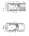
- the anchor bolt 1 partially shown in FIG. 1 contains a cylindrical shaft 2 and an expansion sleeve 4 placed on the rear end 3 of this shaft - in the illustration according to FIG. 1 it is the upper end.
- the cylindrical shaft 2 can, as shown, a smooth coat have surface, it can also be provided with a thread, in particular if use as a composite anchor is desired, in which a composite is produced by means of a mortar compound introduced into the borehole by means of a mortar cartridge.
- the front end of the shaft is adapted to the purpose of the anchor bolt and can have a profile section which is suitable for insertion into a drill or hammer drill.
- the rear end 3 of the shaft 2 tapers, in the case shown in the manner of a truncated cone which is provided with an external thread 5.
- the expansion sleeve 4 has an axial bore 6 which widens conically towards the front and is provided with an internal thread 7 which is adapted to the external thread (see FIG. 2).
- the expansion sleeve 4 In order to allow the expansion sleeve 4 to expand, it has longitudinal slots 8 which are evenly distributed around the circumference and which extend from the front end face 9 of the expansion sleeve so far to the rear that the desired expansion effect can be achieved.
- the rear end face of the expansion sleeve 4 is designated 10, it also forms the rear end of the anchor bolt.
- Cutting elements 11 protrude from the lateral surface of the expansion sleeve 4, by means of which the undercut is produced. These cutting elements 11 must be provided in particular in the area of the lateral surface of the expansion sleeve adjoining the front face 9, since a shoulder-shaped undercut is to be produced in this area as a contact surface for the front face 9 of the expansion sleeve. In the case shown, the cutting elements 11 are formed by cutting inserts. However, corresponding cutting edges could also be formed from the material of the expansion sleeve itself, for example by protruding cutting edges which are formed when the slots 8 are produced the.
- the outer diameter of the expansion sleeve 4 corresponds approximately to the outer diameter of the shaft 2 and the diameter of the envelope of the above cutting elements 11 corresponds approximately to the inner diameter of the predrilled hole into which the anchor bolt is to be inserted. It can also be slightly larger.
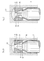
- Fig. 2 shows a longitudinal sectional view of the upper part of the anchor bolt 1 of Fig. 1 inserted into a borehole 12.
- This illustration also shows that the axial bore 6 is expanded conically towards the front (downwards in the drawing) and has the internal thread 7 .
- This bore is also enlarged at the rear in order to reduce the rigidity somewhat in this area in which the longitudinal slots 8 end.
- the anchor bolt is inserted into the pilot hole 12 until, as shown, the rear end face 10 of the expansion sleeve 4 abuts the bottom 13 of the borehole.
- the shaft is now rotated by means of a drilling machine so that the external thread 5 penetrates into the internal thread 7, the expansion sleeve is taken along and the state shown in FIG.
- the expansion sleeve is temporarily entrained in the direction of rotation due to a frictional connection between the external thread of the shaft and the internal thread of the expansion sleeve.
- the force that can be transmitted through the frictional connection must at times be greater than the holding force of the expansion sleeve in the borehole.
- the rotation of the expansion sleeve required for the undercut process when driving in the shaft depends not only on the size and frequency of the impact stress and the distribution of the cutting elements, but also on the angle of inclination of the tapered section and the angle of the tooth flanks of the thread, which are pressed against one another during the impact stress.
- the angle of inclination of the tapered section based on the central axis, is preferably between 10 and 30 °.
- a further control of the entrainment of the expansion sleeve when turning the shaft can also be achieved in that the slopes of the internal thread of the expansion sleeve and the external thread on the tapered section of the shaft are designed somewhat differently from one another. If this measure is provided in the rear area, then it is ensured that at the end of the expansion process of the sleeve, the sleeve rotates with it, so that the expansion sleeve can be seated in the borehole without expansion pressure.
- the threaded connection also forms the positive connection acting in the pulling-out direction of the shaft.
- the front tooth flanks of the external thread applied to the shaft that is to say the tooth flanks which are located on the side facing away from the rear shaft end, run approximately perpendicular to the shaft axis. If the angle of inclination of these tooth flanks with respect to the shaft axis is increased to values above 45 °, a sufficient form fit in the direction of extension of the shaft is no longer guaranteed.
- the cross section of the anchor bolt effective for the tensile load is increased compared to the known anchorages of the type mentioned in the introduction, since a tapered thread is used to anchor the bolt in the expansion sleeve and part of the expansion sleeve is forced into the undercut area of the borehole.
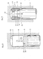
- the example of anchoring shown in FIGS. 4 and 5 differs from that of FIGS. 2 and 3 essentially in that the connection between the shaft and the expansion sleeve is not a saw profile formed by a thread, but a saw profile formed by circumferential grooves.
- the shaft 2 has in the tapering section at the rear end a saw profile 15 formed by circumferential grooves and the expansion sleeve 4 has a complementary saw profile 16.
- the angle of inclination of the rear tooth flanks as already described in the exemplary embodiment in FIGS.
- the measures for the undercut process can be carried out here irrespective of the measures for anchoring the shaft 2 in the expansion sleeve 4, and for example a rotational coupling between the shaft and the expansion sleeve is possible over the entire driving-in process of the shaft.
- a positive engagement acting in the direction of rotation could be provided as in the known methods described in the introduction, which allows the expansion sleeve to be taken along without slippage during the entire setting process.
- the shaft 2 carries, after the tapered section with a saw profile 15, a threaded shoulder 21 which engages in a threaded section 22 of the expansion sleeve 4.
- the expansion sleeve 4 has a circumferential groove approximately in the region in which the longitudinal slots 8 end 23, by means of which the rigidity of the expansion sleeve is reduced at this point and at the same time it is prevented that when the expansion sleeve is expanded in the lower region, the threaded section 22 is deformed to an unacceptable extent.
- This threaded section is provided in connection with the threaded shoulder 21 to provide the necessary axial advance of the shaft 2 during the driving-in movement in addition to or instead of a striking movement by the setting tool.
- the saw profiles 15 and 16 are designed in the same way as in the embodiment according to FIGS. 4 and 5 and also fulfill the same function. Otherwise, the threaded attachment 21 in connection with a threaded section 22 can also be used in an embodiment corresponding to FIGS. 2 and 3. In this case, however, the thread pitches of the thread provided on the tapered section of the shaft 2 and of the thread provided on the thread attachment must be adapted to one another.
- the shaft 2 has a projection 24 which engages in a groove 25 of the expansion sleeve 4 to form a positive connection acting in the direction of rotation.
- the projection 24 is attached to a cylindrical extension 26 of the shaft 2 and the arrangement and length of the groove 25 are selected such that the positive engagement acting in the direction of rotation is released in the rear region of the driving-in section.
- the expansion sleeve has a cutout 27 on the rear side, into which the projection 24 emerges at the end of the driving-in section and can rotate freely.
- the rotational connection does not have to be canceled if a saw profile formed by circumferential grooves is used as the connection between the shaft and the expansion sleeve.
- driver pins 28 are provided to produce a temporary rotation, which are dimensioned so that they shear off by a rotating resistance increasing when driving.
- driver pins of this type it is possible to control the temporary rotation of the expansion sleeve 4 during the undercut process.
- the undercut process can also be ensured if the frictional engagement between the thread flanks cannot be dimensioned sufficiently large.
- the expansion sleeve 4 is formed with at least one run-up edge against which the driver pins abut when the shaft is screwed into the expansion sleeve.
- the front annular end face or an edge of a longitudinal slot 8 can serve as the leading edge.
- a section 29 of the front end face of the expansion sleeve 4 is designed to increase in the circumferential direction, the pitch angle being selected to be somewhat smaller than that of the internal thread of the expansion sleeve, and this section is provided as a leading edge for the driving pins 28.
- the angle of inclination of the tapered portion of the shaft is reduced compared to the first embodiment, which also reduces the forces which can be transmitted by the frictional engagement.
- the shaft 2 is screwed into the sleeve 4, then this is initially spread while the expansion sleeve is held in the borehole until the driving pin 28 shown in FIG. 8 hits the leading edge 29.
- the expansion sleeve is carried along, the leading edge exerting a shear force on the driving pin.
- This shear force fluctuates with a striking load within wide limits if, as shown in the exemplary embodiment according to FIG. 8, a profile 30 is provided on the rear end face of the expansion sleeve 4, which suddenly strikes the holding force of the expansion sleeve in the borehole in the event of an impact load increases.
- the upper driving pin 28 is finally sheared off and, with the expansion sleeve 4 held in the borehole, the shaft 2 is further screwed in until the next driving pin 28 abuts an edge of the expansion sleeve 4 and, with suitable dimensioning, causes the expansion sleeve to be carried briefly while increasing the undercut.
- the expansion sleeve 4 is formed in two parts, one part is rotatably inserted into the borehole and is used to produce the positive connection required in the pull-out direction of the shaft, while the other part for producing the undercut during the driving-in movement of the shaft is also rotated.
- the expansion sleeve 4 consists of the front part 4a and the rear part 4b, which are rotatable relative to one another and are positively connected in the pull-out direction of the shaft.
- the front part 4a of the expansion sleeve is provided with a conical bore 31, the rear part contains a threaded section 22.
- the tapered section to be driven into the conical bore at the rear end of the shaft 2 is conical, the cone angle being approximately the angle of the conical Bore in the spread state of the front part 4a of the expansion sleeve 4 corresponds.
- the shaft 2 carries at the rear end a threaded projection 21 which engages in the threaded section 22 of the expansion sleeve 4 when the anchor bolt is set.
- Retaining pins 33 are provided on the rear end face of the rear part 4b of the expansion sleeve 4, which are intended to ensure that the rear part does not rotate when the shaft 2 is driven into the expansion sleeve.
- the shaft has projections which protrude from the conical surface and which protrude into the longitudinal slots 8 of the front part 4a of the expansion sleeve fen.
- the shaft is driven into the expansion sleeve 4 by means of a rotating movement.
- the rear part 4b is held by the retaining pins 33 in the borehole, while the front part 4a is rotated as a result of the engagement between the projections 34 and the slots 8.
- the front part 4a of the expansion sleeve is spread and the undercut is produced in the borehole by the axial movement which the shaft 2 carries out.
- the threaded shoulder 21 of the shaft 2 is screwed into the threaded section 22 of the expansion sleeve 4.
- This threaded connection then represents the positive connection acting in the pulling-out direction of the shaft.
- the front and the rear part of the expansion sleeve 4 can be two separate ring parts which, as shown in FIG. 9, are held on the shaft 2 in that one or two threads of the threaded projection 21 engage in the threaded section 22.
- connection between the shaft and the front part 4a of the expansion sleeve 4 is designed as a cone connection with a smooth outer surface.
- a threaded connection as in the first exemplary embodiment or a saw profile formed by circumferential grooves as in the second exemplary embodiment can also be selected here.
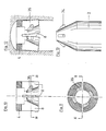
- FIG. 10 shows a longitudinal section of the expansion sleeve 4
- FIG. 11 shows the section XI-XI from FIG. 10
- FIG. 12 shows one of FIG. 10 corresponding representation of the expansion sleeve in the expanded state within the borehole and
- FIG. 13 the rear part of the shaft 2.
- Four projections 34 are provided on the shaft, each of which engages in an axially aligned groove, that is to say in the present case in a longitudinal slot 8 of the expansion sleeve 4.
- the expansion sleeve can be set in rotation when driving in via the rotary connection formed in this way.
- a circumferential groove 35 which is connected to the relevant axial groove 8, is assigned to each axially aligned groove 8 at the end of the driving-in section.
- the protrusions 34 are inserted into the circumferential grooves 35 by the stripping movement, thereby producing the positive connection between the shaft and the expansion sleeve that acts in the pull-out direction of the shaft.
- the shaft has been shown as a full shaft in the exemplary embodiments, it can also be hollow. Likewise, the slots of the expansion sleeve do not need to run parallel to the central axis of the expansion sleeve, but can be arranged obliquely.
- the bore of the expansion sleeve does not have to have the same taper angle as the tapered section of the shaft. It can also be cylindrical in the area receiving the tapering section.
- the complementary saw profile present in the expansion sleeve does not have to be exactly adapted to the tapering section of the shaft. It is essential that the functions described in this application be fulfilled. In view of this, it is more convenient if the profiles in the spread state are matched to each other than in the non-spread state.
- the shaft 2 is hollow, i.e. in the form of a sleeve and this has an internal thread.
- a connection in the form of a saw profile, preferably a threaded connection, similar to the example according to FIG. 1, is provided between the shaft and the expansion sleeve 4.
- the longitudinal slots 8 of the expansion sleeve 4 end shortly in front of the front end face 9, in order initially to achieve a higher frictional engagement when screwing the shaft 2 into the expansion sleeve 4.
- the thin connecting webs at the front end of the longitudinal slots 8 break and the expansion sleeve is expanded as described.
- Protruding cutting edges 11 arranged helically are provided here as cutting elements.
- the arrangement of the helical lines can be opposite in the case of a sleeve, as shown in FIG. 14. Otherwise, retaining strips 14 are provided on the rear end face, which correspond to the retaining pins 33 of the embodiment according to FIG. 9.
Landscapes
- Engineering & Computer Science (AREA)
- General Engineering & Computer Science (AREA)
- Mechanical Engineering (AREA)
- Dowels (AREA)
- Joining Of Building Structures In Genera (AREA)
Priority Applications (1)
| Application Number | Priority Date | Filing Date | Title |
|---|---|---|---|
| AT87107025T ATE45015T1 (de) | 1986-05-16 | 1987-05-14 | Verfahren zum einsetzen eines ankerbolzens in ein bohrloch eines befestigungsgrundes und ankerbolzen fuer dieses verfahren. |
Applications Claiming Priority (4)
| Application Number | Priority Date | Filing Date | Title |
|---|---|---|---|
| DE3616654 | 1986-05-16 | ||
| DE3616654 | 1986-05-16 | ||
| DE19873702336 DE3702336A1 (de) | 1986-05-16 | 1987-01-27 | Verfahren zum einsetzen eines ankerbolzens in ein bohrloch eines befestigungsgrundes und ankerbolzen fuer dieses verfahren |
| DE3702336 | 1987-01-27 |
Publications (3)
| Publication Number | Publication Date |
|---|---|
| EP0245865A2 true EP0245865A2 (fr) | 1987-11-19 |
| EP0245865A3 EP0245865A3 (en) | 1988-01-13 |
| EP0245865B1 EP0245865B1 (fr) | 1989-07-26 |
Family
ID=25843849
Family Applications (1)
| Application Number | Title | Priority Date | Filing Date |
|---|---|---|---|
| EP87107025A Expired EP0245865B1 (fr) | 1986-05-16 | 1987-05-14 | Procédé de pose d'une goupille d'ancrage dans un trou foré d'un support et goupille d'ancrage à utiliser avec ce procédé |
Country Status (2)
| Country | Link |
|---|---|
| EP (1) | EP0245865B1 (fr) |
| DE (2) | DE3702336A1 (fr) |
Cited By (3)
| Publication number | Priority date | Publication date | Assignee | Title |
|---|---|---|---|---|
| EP0331816A3 (en) * | 1988-02-27 | 1990-09-26 | Fischerwerke Artur Fischer Gmbh & Co. Kg | By impact expandible plug |
| KR101283444B1 (ko) * | 2012-03-22 | 2013-07-08 | 배정운 | 수평형 파워 led 소자 및 그 제조방법 |
| EP2927511A1 (fr) * | 2014-04-01 | 2015-10-07 | HILTI Aktiengesellschaft | Vis dotée d'un piston d'éjection de masse |
Families Citing this family (2)
| Publication number | Priority date | Publication date | Assignee | Title |
|---|---|---|---|---|
| DE3813877A1 (de) * | 1988-04-25 | 1989-11-02 | Karl Eischeid | Verankerungsvorrichtung eines gewindebauteils in einer hinterschnittbohrung |
| DE4010999A1 (de) * | 1989-07-04 | 1991-01-17 | Helmut Stoffel | Befestigungselement |
Family Cites Families (3)
| Publication number | Priority date | Publication date | Assignee | Title |
|---|---|---|---|---|
| DE1775064A1 (de) * | 1968-06-08 | 1971-05-19 | Artur Fischer | In einem Bohrloch einer Wand verankerbares Befestigungselement |
| DE8125545U1 (de) * | 1981-09-02 | 1982-04-15 | Upat Gmbh & Co, 7830 Emmendingen | Bohrkrone |
| DE3237059A1 (de) * | 1982-10-06 | 1984-04-12 | Hilti AG, 9494 Schaan | Spreizduebel mit gewindebolzen und spreizhuelse |
-
1987
- 1987-01-27 DE DE19873702336 patent/DE3702336A1/de not_active Withdrawn
- 1987-05-14 EP EP87107025A patent/EP0245865B1/fr not_active Expired
- 1987-05-14 DE DE8787107025T patent/DE3760375D1/de not_active Expired
Cited By (6)
| Publication number | Priority date | Publication date | Assignee | Title |
|---|---|---|---|---|
| EP0331816A3 (en) * | 1988-02-27 | 1990-09-26 | Fischerwerke Artur Fischer Gmbh & Co. Kg | By impact expandible plug |
| KR101283444B1 (ko) * | 2012-03-22 | 2013-07-08 | 배정운 | 수평형 파워 led 소자 및 그 제조방법 |
| EP2927511A1 (fr) * | 2014-04-01 | 2015-10-07 | HILTI Aktiengesellschaft | Vis dotée d'un piston d'éjection de masse |
| WO2015150351A1 (fr) * | 2014-04-01 | 2015-10-08 | Hilti Aktiengesellschaft | Vis munie d'un piston de refoulement de matière |
| CN106133340A (zh) * | 2014-04-01 | 2016-11-16 | 喜利得股份公司 | 具有物料挤出活塞的螺纹件 |
| CN106133340B (zh) * | 2014-04-01 | 2019-01-29 | 喜利得股份公司 | 具有物料挤出活塞的螺纹件及其安装方法 |
Also Published As
| Publication number | Publication date |
|---|---|
| DE3760375D1 (en) | 1989-08-31 |
| EP0245865B1 (fr) | 1989-07-26 |
| EP0245865A3 (en) | 1988-01-13 |
| DE3702336A1 (de) | 1987-11-19 |
Similar Documents
| Publication | Publication Date | Title |
|---|---|---|
| EP0068227B1 (fr) | Boulon d'ancrage | |
| DE2607338C2 (de) | Schlagdübel mit Spreizhülse und Spreizelement | |
| EP0308619B1 (fr) | Chéville à expansion | |
| DE69006170T2 (de) | Schraubdübel, insbesondere für weiches Material, und dafür geeignetes Werkzeug. | |
| EP1301719A1 (fr) | Element d'ancrage contre-depouille pouvant etre monte par liaison de forme | |
| EP0499580B1 (fr) | Outil d'extraction | |
| CH650064A5 (de) | Verfahren zum setzen eines ankerbolzens und ankerbolzen zu dessen durchfuehrung. | |
| EP3640487A1 (fr) | Vis à bois dotée d'une projection en forme d'arc entre les pas de vis | |
| EP0811775A1 (fr) | Cheville d'ancrage autocoupante | |
| DE69707088T2 (de) | Selbstbohrender ankerbolzen | |
| EP0375606B1 (fr) | Dispositif d'attache | |
| EP1235988A1 (fr) | Vis pour fixer avec un ecart, des panneaux de recouvrement ou des rails sur une infrastructure | |
| EP0824198A1 (fr) | Vis ayant une pointe autoperçante | |
| DE2718147A1 (de) | Spreizanker | |
| EP1412644B1 (fr) | Cheville a expansion | |
| DE3139174C2 (de) | Ankerbolzen | |
| EP0245865B1 (fr) | Procédé de pose d'une goupille d'ancrage dans un trou foré d'un support et goupille d'ancrage à utiliser avec ce procédé | |
| EP0406548A1 (fr) | Ancrage de boulon avec filetage au moyen d'une matière composite | |
| DE19607446A1 (de) | Schlagdübel | |
| DE3524284C2 (de) | Befestigungsvorrichtung | |
| EP0381678B1 (fr) | Cheville a contre-depouille | |
| DE3502607A1 (de) | Anker, insbesondere lastabhaengiger duebel | |
| CH630150A5 (de) | Duebel mit befestigungsschraube. | |
| DE19743054A1 (de) | Schraubanker | |
| EP0503677A2 (fr) | Ancre pour des charges lourdes |
Legal Events
| Date | Code | Title | Description |
|---|---|---|---|
| PUAI | Public reference made under article 153(3) epc to a published international application that has entered the european phase |
Free format text: ORIGINAL CODE: 0009012 |
|
| AK | Designated contracting states |
Kind code of ref document: A2 Designated state(s): AT BE CH DE FR GB IT LI NL SE |
|
| PUAL | Search report despatched |
Free format text: ORIGINAL CODE: 0009013 |
|
| AK | Designated contracting states |
Kind code of ref document: A3 Designated state(s): AT BE CH DE FR GB IT LI NL SE |
|
| 17P | Request for examination filed |
Effective date: 19880701 |
|
| 17Q | First examination report despatched |
Effective date: 19880912 |
|
| GRAA | (expected) grant |
Free format text: ORIGINAL CODE: 0009210 |
|
| AK | Designated contracting states |
Kind code of ref document: B1 Designated state(s): AT CH DE LI |
|
| REF | Corresponds to: |
Ref document number: 45015 Country of ref document: AT Date of ref document: 19890815 Kind code of ref document: T |
|
| REF | Corresponds to: |
Ref document number: 3760375 Country of ref document: DE Date of ref document: 19890831 |
|
| PLBE | No opposition filed within time limit |
Free format text: ORIGINAL CODE: 0009261 |
|
| STAA | Information on the status of an ep patent application or granted ep patent |
Free format text: STATUS: NO OPPOSITION FILED WITHIN TIME LIMIT |
|
| 26N | No opposition filed | ||
| PGFP | Annual fee paid to national office [announced via postgrant information from national office to epo] |
Ref country code: CH Payment date: 19920414 Year of fee payment: 6 |
|
| PGFP | Annual fee paid to national office [announced via postgrant information from national office to epo] |
Ref country code: AT Payment date: 19920416 Year of fee payment: 6 |
|
| PGFP | Annual fee paid to national office [announced via postgrant information from national office to epo] |
Ref country code: DE Payment date: 19920526 Year of fee payment: 6 |
|
| PG25 | Lapsed in a contracting state [announced via postgrant information from national office to epo] |
Ref country code: AT Effective date: 19930514 |
|
| PG25 | Lapsed in a contracting state [announced via postgrant information from national office to epo] |
Ref country code: LI Effective date: 19930531 Ref country code: CH Effective date: 19930531 |
|
| REG | Reference to a national code |
Ref country code: CH Ref legal event code: PL |
|
| PG25 | Lapsed in a contracting state [announced via postgrant information from national office to epo] |
Ref country code: DE Effective date: 19940201 |