EP0246036A1 - Filtrationssystem - Google Patents
Filtrationssystem Download PDFInfo
- Publication number
- EP0246036A1 EP0246036A1 EP87304101A EP87304101A EP0246036A1 EP 0246036 A1 EP0246036 A1 EP 0246036A1 EP 87304101 A EP87304101 A EP 87304101A EP 87304101 A EP87304101 A EP 87304101A EP 0246036 A1 EP0246036 A1 EP 0246036A1
- Authority
- EP
- European Patent Office
- Prior art keywords
- filter
- porous
- filter system
- liquid
- expanded polytetrafluoroethylene
- Prior art date
- Legal status (The legal status is an assumption and is not a legal conclusion. Google has not performed a legal analysis and makes no representation as to the accuracy of the status listed.)
- Withdrawn
Links
Images

Classifications
-
- B—PERFORMING OPERATIONS; TRANSPORTING
- B01—PHYSICAL OR CHEMICAL PROCESSES OR APPARATUS IN GENERAL
- B01D—SEPARATION
- B01D61/00—Processes of separation using semi-permeable membranes, e.g. dialysis, osmosis or ultrafiltration; Apparatus, accessories or auxiliary operations specially adapted therefor
- B01D61/14—Ultrafiltration; Microfiltration
- B01D61/147—Microfiltration
-
- B—PERFORMING OPERATIONS; TRANSPORTING
- B01—PHYSICAL OR CHEMICAL PROCESSES OR APPARATUS IN GENERAL
- B01D—SEPARATION
- B01D29/00—Filters with filtering elements stationary during filtration, e.g. pressure or suction filters, not covered by groups B01D24/00 - B01D27/00; Filtering elements therefor
- B01D29/11—Filters with filtering elements stationary during filtration, e.g. pressure or suction filters, not covered by groups B01D24/00 - B01D27/00; Filtering elements therefor with bag, cage, hose, tube, sleeve or like filtering elements
- B01D29/13—Supported filter elements
- B01D29/23—Supported filter elements arranged for outward flow filtration
-
- B—PERFORMING OPERATIONS; TRANSPORTING
- B01—PHYSICAL OR CHEMICAL PROCESSES OR APPARATUS IN GENERAL
- B01D—SEPARATION
- B01D29/00—Filters with filtering elements stationary during filtration, e.g. pressure or suction filters, not covered by groups B01D24/00 - B01D27/00; Filtering elements therefor
- B01D29/11—Filters with filtering elements stationary during filtration, e.g. pressure or suction filters, not covered by groups B01D24/00 - B01D27/00; Filtering elements therefor with bag, cage, hose, tube, sleeve or like filtering elements
- B01D29/13—Supported filter elements
- B01D29/23—Supported filter elements arranged for outward flow filtration
- B01D29/232—Supported filter elements arranged for outward flow filtration with corrugated, folded or wound sheets
-
- B—PERFORMING OPERATIONS; TRANSPORTING
- B01—PHYSICAL OR CHEMICAL PROCESSES OR APPARATUS IN GENERAL
- B01D—SEPARATION
- B01D35/00—Filtering devices having features not specifically covered by groups B01D24/00 - B01D33/00, or for applications not specifically covered by groups B01D24/00 - B01D33/00; Auxiliary devices for filtration; Filter housing constructions
- B01D35/02—Filters adapted for location in special places, e.g. pipe-lines, pumps, stop-cocks
- B01D35/027—Filters adapted for location in special places, e.g. pipe-lines, pumps, stop-cocks rigidly mounted in or on tanks or reservoirs
- B01D35/0273—Filtering elements with a horizontal or inclined rotation or symmetry axis submerged in tanks or reservoirs
-
- B—PERFORMING OPERATIONS; TRANSPORTING
- B01—PHYSICAL OR CHEMICAL PROCESSES OR APPARATUS IN GENERAL
- B01D—SEPARATION
- B01D61/00—Processes of separation using semi-permeable membranes, e.g. dialysis, osmosis or ultrafiltration; Apparatus, accessories or auxiliary operations specially adapted therefor
- B01D61/14—Ultrafiltration; Microfiltration
- B01D61/18—Apparatus therefor
-
- B—PERFORMING OPERATIONS; TRANSPORTING
- B01—PHYSICAL OR CHEMICAL PROCESSES OR APPARATUS IN GENERAL
- B01D—SEPARATION
- B01D63/00—Apparatus in general for separation processes using semi-permeable membranes
- B01D63/06—Tubular membrane modules
- B01D63/067—Tubular membrane modules with pleated membranes
-
- B—PERFORMING OPERATIONS; TRANSPORTING
- B01—PHYSICAL OR CHEMICAL PROCESSES OR APPARATUS IN GENERAL
- B01D—SEPARATION
- B01D63/00—Apparatus in general for separation processes using semi-permeable membranes
- B01D63/06—Tubular membrane modules
- B01D63/069—Tubular membrane modules comprising a bundle of tubular membranes
-
- B—PERFORMING OPERATIONS; TRANSPORTING
- B01—PHYSICAL OR CHEMICAL PROCESSES OR APPARATUS IN GENERAL
- B01D—SEPARATION
- B01D2201/00—Details relating to filtering apparatus
- B01D2201/04—Supports for the filtering elements
- B01D2201/0407—Perforated supports on both sides of the filtering element
Definitions
- the present invention concerns a filter system.
- a relatively low-cost filter system is provided which is easy to handle and control and which performs a reliable and precise filtering action.
- the present invention is particularly useful in filtering chemicals used in the field of semiconductor manufacture, in the food industry and in other fields.
- FIG 4 is a schematic partial sectional view of a filter system.
- the liquid 40 (chemical solution or water) that is to be purified is temporarily conducted out of the tank 43, purified by means of a pump 41 and filter 42, and then recirculated back into the tank 43.
- Various proposals have been made regarding the piping and connections involved, pumps and filters having good sealing properties, and methods for sealing internal cartridges in such filters.
- a filter system comprising a filter of porous, expanded polytetrafluoroethylene and means for flowing an impure liquid to be filtered through the filter, the filter system being entirely immersed in the impure liquid.
- the filter may be a hollow fiber of porous, expanded polytetrafluoroethylene, a tube of porous, expanded polytetrafluoroethylene or a supported film of porous, expanded polytetrafluoroethylene.
- the filter is a plurality of hollow fibers of porous, expanded polytetrafluoroethylene or a plurality of tubes of porous, expanded polytetrafluoroethylene.
- a filter system having a filter of porous, expanded polytetrafluoroethylene, means for flowing an impure liquid to be filtered through the filter, the filter system being entirely immersed in the impure liquid to be filtered.
- the filter - is preferably in the form of a plurality of hollow fibers, a plurality of tubes or a supported film.
- the filter system includes (a) a filter which has an internal cavity and (b) one or more headers which connect the ends of the aforementioned filter, the filter system being characterized in that the aforementioned filter is designed so that it can be used entirely immersed in the liquid to be filtered, without having any external tube or case requiring sealing properties.
- the filter is immersed in the liquid that is to be filtered, and filtration of the liquid is performed by causing the flow of the liquid through the filter by means of a pressure-feeding mechanism such as a pump.
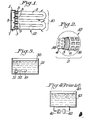
- a filter 10 having a header 1 which has a flow path 8 formed in its interior, and which has an inlet port 7 installed in the flow path 8. Both ends of filter tubes 2 are coupled to coupling ports 9 which are installed in the aforementioned header 1. These coupling ports are sealed by means of heat-shrink sealing tubes 3. The flow path through the filter 10 is in the direction indicated by the arrows.
- FIG. 2 One example of the structure of the aforementioned filter tubes 2 is shown in Figure 2 in an enlarged partial pictorial view of the read-out circle 12 of Figure 1.
- a porous filtering membrane 5 is mounted between a supporting inner tube 4 which has openings 14 formed in it, and a supporting outer tube 6 which similarly has openings 16 formed in it.
- a hollow tube-form membrane, a hollow fiber-form membrane, film-form membrane or tape-form membrane may be used for the aforementioned filtering membrane 5, and depending on the dimensional conditions, one or both of the supporting inner tube 4 and supporting outer tube 6 may be omitted.
- the tube used does not have pressure-resistant sealing properties (as in the case of the conventional mechanism shown in Figure 4); i.e. the tube need merely be sufficiently strong to maintain the shape of the filtering membrane 5.
- the tape-form membrane may be wrapped in a spiral form with partial overlapping around the outside of the aforementioned supporting inner tube 4.
- both ends of the filter tubes 2 are coupled to coupling ports 9.
- FIG. 3 The conditions of utilization of the filter system constructed as described above, are illustrated in Figure 3.
- a pump 31 which can be used immersed in a liquid 30, the discharge port of the pump 31 and the aforementioned inlet port 7 are appropriately connected by means of a connecting pipe 32 inside a tank 33 which contains the liquid 30 that is to be filtered.
- the filter system (which comprises the aforementioned header 1 and filter tubes 2 as shown in Figure 1) is set in the bottom of the aforementioned tank 33, and the pump 31 is driven. As a result, an effective filtering purification action is performed inside the tank 33.
- Dimensional conditions such as the material, thickness and pore size of the filtering membrane 5 can be selected as desired in accordance with the type of liquid that is to be treated and the purpose of filtration.
- porous materials made of fluororesins have wide applicability in terms of chemical resistance to the aforementioned strong acids and other compounds.
- a membrane manufactured from a polytetrafluoroethylene resin made porous by rolling and stretching as disclosed in U.S. Patent 3,953,566, with a membrane thickness of approximately 40 to 70 microns and a pore size of approximately 0.1 to 1.0 microns is desirable, and allows high-precision filtration to be achieved.
- the aforementioned supporting inner tube 4 and supporting outer tube 6 can be appropriately employed.
- a supporting body - filtering membrane - supporting body structure or a filtering membrane - supporting body structure can be used.
- the membrane in the case of such a film-form filtering membrane, the membrane can be pleated as shown pictorially and in cross-section in Figure 5, so that the filtration area is increased.
- the film in the case of a film-form membrane, the film may be clamped between supports 4A and 6A having openings, which supports may be nets or screens, on both sides, or may be laminated with a net which acts as a supporting body.
- pleats may be formed so that the tubes have a star-shaped cross-section as shown in Figure 5 or other cross-section.
- a header 1 such as that described above
- multiple filter tubes 2 are generally used.
- a part which is used as a header facing the header 1 shown in Figure 1 need not have a flow path formed in its interior. Such a part need merely be able to maintain the filter tubes 2 in their prescribed positions.
- the sheet-form membrane may be clamped between supporting parts lA and 1B on both sides, folded into pleats and thermally fused into a conduit form as shown in Figure 6, thus producing a structure 2B with the cross-section shown in Figure 7.
- the ends of such a conduit are attached to headers as shown in Figure 6. In addition to heat-shrink tubes 3, this attachment may be effected by thermal fusion.
- the filter system constructed as described above may be used entirely immersed in a tank such as an etching tank or washing tank, as shown in Figure 3. There is no escape of the liquid (chemical solution or water) due to leaks. Furthermore, the generation of impurities from the piping can be minimized. Thus, the tightly sealed outer tubes, caps or cases, which are used in conventional filter systems (as illustrated in Figure 4), can be completely omitted. Accordingly, the filter system is simple and inexpensive.
- filtration can be performed simply and inexpensively. Because the filter is used under conditions in which it is surrounded by the pressure of the liquid being filtered, there is no danger of the escape of the liquid (chemical solution or water) to the environment due to breakage of the filter. Filtration can be performed under conditions in which maintenance and control are safe and easy. Safe operation can be performed in which there is neither need for air extraction nor will any blocking by air occur. Thus, there are numerous improved features and great industrial merit.
Landscapes
- Chemical & Material Sciences (AREA)
- Chemical Kinetics & Catalysis (AREA)
- Engineering & Computer Science (AREA)
- Water Supply & Treatment (AREA)
- Separation Using Semi-Permeable Membranes (AREA)
- Filtration Of Liquid (AREA)
Applications Claiming Priority (2)
| Application Number | Priority Date | Filing Date | Title |
|---|---|---|---|
| JP61106590A JPS62266109A (ja) | 1986-05-12 | 1986-05-12 | フイルタ−機構 |
| JP106590/86 | 1986-05-12 |
Publications (1)
| Publication Number | Publication Date |
|---|---|
| EP0246036A1 true EP0246036A1 (de) | 1987-11-19 |
Family
ID=14437398
Family Applications (1)
| Application Number | Title | Priority Date | Filing Date |
|---|---|---|---|
| EP87304101A Withdrawn EP0246036A1 (de) | 1986-05-12 | 1987-05-08 | Filtrationssystem |
Country Status (4)
| Country | Link |
|---|---|
| EP (1) | EP0246036A1 (de) |
| JP (1) | JPS62266109A (de) |
| AU (1) | AU7254587A (de) |
| GB (1) | GB2190306A (de) |
Cited By (5)
| Publication number | Priority date | Publication date | Assignee | Title |
|---|---|---|---|---|
| GB2223690A (en) * | 1988-10-17 | 1990-04-18 | Roger Stanley White | Filter tubes |
| EP0562321A1 (de) * | 1992-03-25 | 1993-09-29 | Gütling Gmbh | Ölabscheider mit integrierter Mikrofiltrations-Einrichtung |
| EP0563646A1 (de) * | 1992-03-25 | 1993-10-06 | Gütling Gmbh | Querstromfiltrationsanlage mit Eintauch-Umwälzpumpe |
| GB2280388A (en) * | 1993-07-26 | 1995-02-01 | Numatic Int Ltd | Vacuum cleaner filter |
| DE19916880A1 (de) * | 1999-04-14 | 2000-10-19 | Isarbaustoff Gmbh & Co Kg | Mineralölabscheider |
Families Citing this family (2)
| Publication number | Priority date | Publication date | Assignee | Title |
|---|---|---|---|---|
| GB8903540D0 (en) * | 1989-02-16 | 1989-04-05 | Gore & Ass | A cross-flow filtration,or other,device having a porous tubular polytetrafluoroethylene membrane secured in an apertured wall,and the method of its manufacture |
| GB0906751D0 (en) * | 2009-04-18 | 2009-06-03 | Fairey Filtration Systems Ltd | Filter |
Citations (4)
| Publication number | Priority date | Publication date | Assignee | Title |
|---|---|---|---|---|
| US3108065A (en) * | 1959-09-29 | 1963-10-22 | Gen Motors Corp | Fuel tank strainer |
| CH375995A (de) * | 1960-01-23 | 1964-03-15 | Sulzer Ag | Rohwasserpumpwerk |
| US3813461A (en) * | 1971-02-03 | 1974-05-28 | Kureha Chemical Ind Co Ltd | Process for producing porous articles of polytetrafluoroethylene |
| US4187390A (en) * | 1970-05-21 | 1980-02-05 | W. L. Gore & Associates, Inc. | Porous products and process therefor |
Family Cites Families (8)
| Publication number | Priority date | Publication date | Assignee | Title |
|---|---|---|---|---|
| NL242918A (de) * | 1958-09-22 | |||
| DE2205277B2 (de) * | 1971-02-09 | 1979-06-28 | Canon K.K., Tokio | Elektrophotographisches Reproduktionsgerät |
| GB1385799A (en) * | 1972-02-15 | 1975-02-26 | Sp Konstr Ktorskoe Bjuro Gidro | Method and apparatus to refine melts from solid impurities |
| PL84385B1 (de) * | 1973-01-11 | 1976-03-31 | Polotechnika Wroclawska Breslau (Polen) | |
| DE2641023A1 (de) * | 1975-09-15 | 1977-03-24 | Orensten | Wasserbehandlungsvorrichtung |
| US4025679A (en) * | 1976-08-06 | 1977-05-24 | W. L. Gore & Associates, Inc. | Fibrillated polytetrafluoroethylene woven filter fabric |
| JPS5763103A (en) * | 1980-09-30 | 1982-04-16 | Yuasa Battery Co Ltd | Filter |
| GB2153247A (en) * | 1984-01-31 | 1985-08-21 | Baxter Travenol Lab | Filter |
-
1986
- 1986-05-12 JP JP61106590A patent/JPS62266109A/ja active Pending
-
1987
- 1987-05-06 AU AU72545/87A patent/AU7254587A/en not_active Abandoned
- 1987-05-08 GB GB08710987A patent/GB2190306A/en not_active Withdrawn
- 1987-05-08 EP EP87304101A patent/EP0246036A1/de not_active Withdrawn
Patent Citations (4)
| Publication number | Priority date | Publication date | Assignee | Title |
|---|---|---|---|---|
| US3108065A (en) * | 1959-09-29 | 1963-10-22 | Gen Motors Corp | Fuel tank strainer |
| CH375995A (de) * | 1960-01-23 | 1964-03-15 | Sulzer Ag | Rohwasserpumpwerk |
| US4187390A (en) * | 1970-05-21 | 1980-02-05 | W. L. Gore & Associates, Inc. | Porous products and process therefor |
| US3813461A (en) * | 1971-02-03 | 1974-05-28 | Kureha Chemical Ind Co Ltd | Process for producing porous articles of polytetrafluoroethylene |
Cited By (6)
| Publication number | Priority date | Publication date | Assignee | Title |
|---|---|---|---|---|
| GB2223690A (en) * | 1988-10-17 | 1990-04-18 | Roger Stanley White | Filter tubes |
| GB2223690B (en) * | 1988-10-17 | 1991-05-01 | Roger Stanley White | Filtration systems |
| EP0562321A1 (de) * | 1992-03-25 | 1993-09-29 | Gütling Gmbh | Ölabscheider mit integrierter Mikrofiltrations-Einrichtung |
| EP0563646A1 (de) * | 1992-03-25 | 1993-10-06 | Gütling Gmbh | Querstromfiltrationsanlage mit Eintauch-Umwälzpumpe |
| GB2280388A (en) * | 1993-07-26 | 1995-02-01 | Numatic Int Ltd | Vacuum cleaner filter |
| DE19916880A1 (de) * | 1999-04-14 | 2000-10-19 | Isarbaustoff Gmbh & Co Kg | Mineralölabscheider |
Also Published As
| Publication number | Publication date |
|---|---|
| JPS62266109A (ja) | 1987-11-18 |
| GB2190306A (en) | 1987-11-18 |
| AU7254587A (en) | 1987-11-19 |
| GB8710987D0 (en) | 1987-06-10 |
Similar Documents
| Publication | Publication Date | Title |
|---|---|---|
| US6702941B1 (en) | Fluid treatment elements adapted for cross flow treatment | |
| US4707268A (en) | Hollow fiber potted microfilter | |
| EP0207379B1 (de) | Hohlfaserfiltermodul und Filtrationsverfahren unter Verwendung desselben | |
| US4032454A (en) | Permselective membrane apparatus with porous support | |
| JPH1066836A (ja) | デッド容積の少ない使い捨て型の膜モジュール | |
| GB2134812A (en) | Liquid filter | |
| CN101925395B (zh) | 中空纤维膜元件、用于中空纤维膜元件的框架以及膜过滤装置 | |
| WO2007075862A2 (en) | Filtration assembly and methods for making and using same | |
| EP0246036A1 (de) | Filtrationssystem | |
| CN100361729C (zh) | 用于形成气体传递膜的褶式结构 | |
| KR102810633B1 (ko) | 관형 여과막 모듈 | |
| KR20050047230A (ko) | 침지형 중공사막 모듈 | |
| WO1984001522A1 (en) | Filter | |
| KR101557544B1 (ko) | 중공사막 모듈 | |
| JPH0768103A (ja) | 膜脱気方法 | |
| TWI861633B (zh) | 具有改良沖洗之過濾器的方法和系統 | |
| JP3272847B2 (ja) | 複数結合型中空糸膜モジュール | |
| US4704205A (en) | Tubular membrane module wherein liquid flows around stay bolt | |
| JPS6068007A (ja) | 流体の分離装置 | |
| CN212440281U (zh) | 一种可反冲洗的不锈钢管式多层烧结滤网精密过滤装置 | |
| EP1762293A2 (de) | Elemente und Verfahren zur Behandlung von Fluiden | |
| JPH0213069Y2 (de) | ||
| JP2728415B2 (ja) | 濾過フィルター | |
| JPH0213067Y2 (de) | ||
| JPH0123161B2 (de) |
Legal Events
| Date | Code | Title | Description |
|---|---|---|---|
| PUAI | Public reference made under article 153(3) epc to a published international application that has entered the european phase |
Free format text: ORIGINAL CODE: 0009012 |
|
| AK | Designated contracting states |
Kind code of ref document: A1 Designated state(s): AT BE CH DE ES FR GB GR IT LI LU NL SE |
|
| 17P | Request for examination filed |
Effective date: 19880415 |
|
| 17Q | First examination report despatched |
Effective date: 19890606 |
|
| STAA | Information on the status of an ep patent application or granted ep patent |
Free format text: STATUS: THE APPLICATION IS DEEMED TO BE WITHDRAWN |
|
| 18D | Application deemed to be withdrawn |
Effective date: 19891017 |
|
| RIN1 | Information on inventor provided before grant (corrected) |
Inventor name: SHIBATA, YOSHIHIKO Inventor name: ICHIYASU, SATOSHI |