EP0246191A2 - Behandlung fester Teilchen in einer Wirbelschicht mit Brenner - Google Patents
Behandlung fester Teilchen in einer Wirbelschicht mit Brenner Download PDFInfo
- Publication number
- EP0246191A2 EP0246191A2 EP87810289A EP87810289A EP0246191A2 EP 0246191 A2 EP0246191 A2 EP 0246191A2 EP 87810289 A EP87810289 A EP 87810289A EP 87810289 A EP87810289 A EP 87810289A EP 0246191 A2 EP0246191 A2 EP 0246191A2
- Authority
- EP
- European Patent Office
- Prior art keywords
- velocity
- oxidant
- fuel
- fluidized bed
- bed
- Prior art date
- Legal status (The legal status is an assumption and is not a legal conclusion. Google has not performed a legal analysis and makes no representation as to the accuracy of the status listed.)
- Withdrawn
Links
- 239000007787 solid Substances 0.000 title claims abstract description 97
- 239000002245 particle Substances 0.000 claims abstract description 75
- 238000000034 method Methods 0.000 claims abstract description 54
- 230000008569 process Effects 0.000 claims abstract description 53
- 238000007669 thermal treatment Methods 0.000 claims abstract description 18
- 239000012530 fluid Substances 0.000 claims abstract description 13
- 239000000446 fuel Substances 0.000 claims description 57
- 239000007800 oxidant agent Substances 0.000 claims description 44
- 230000001590 oxidative effect Effects 0.000 claims description 43
- 238000002156 mixing Methods 0.000 claims description 37
- 238000001354 calcination Methods 0.000 claims description 5
- 238000005054 agglomeration Methods 0.000 claims description 4
- 230000002776 aggregation Effects 0.000 claims description 4
- 230000003647 oxidation Effects 0.000 claims description 3
- 238000007254 oxidation reaction Methods 0.000 claims description 3
- 238000010438 heat treatment Methods 0.000 claims description 2
- 230000003134 recirculating effect Effects 0.000 claims description 2
- 238000007599 discharging Methods 0.000 claims 4
- 230000000452 restraining effect Effects 0.000 claims 1
- 230000009471 action Effects 0.000 abstract description 7
- 238000005243 fluidization Methods 0.000 abstract description 3
- 238000012423 maintenance Methods 0.000 abstract description 2
- 239000007789 gas Substances 0.000 description 46
- XEEYBQQBJWHFJM-UHFFFAOYSA-N Iron Chemical compound [Fe] XEEYBQQBJWHFJM-UHFFFAOYSA-N 0.000 description 12
- UQSXHKLRYXJYBZ-UHFFFAOYSA-N Iron oxide Chemical compound [Fe]=O UQSXHKLRYXJYBZ-UHFFFAOYSA-N 0.000 description 10
- VNWKTOKETHGBQD-UHFFFAOYSA-N methane Chemical compound C VNWKTOKETHGBQD-UHFFFAOYSA-N 0.000 description 9
- 238000002485 combustion reaction Methods 0.000 description 8
- 239000000203 mixture Substances 0.000 description 8
- VYPSYNLAJGMNEJ-UHFFFAOYSA-N Silicium dioxide Chemical compound O=[Si]=O VYPSYNLAJGMNEJ-UHFFFAOYSA-N 0.000 description 7
- 229910052742 iron Inorganic materials 0.000 description 6
- RYGMFSIKBFXOCR-UHFFFAOYSA-N Copper Chemical compound [Cu] RYGMFSIKBFXOCR-UHFFFAOYSA-N 0.000 description 5
- 229910052802 copper Inorganic materials 0.000 description 5
- 239000010949 copper Substances 0.000 description 5
- 239000004576 sand Substances 0.000 description 5
- 239000002699 waste material Substances 0.000 description 5
- 238000006243 chemical reaction Methods 0.000 description 4
- 230000001419 dependent effect Effects 0.000 description 4
- 239000007788 liquid Substances 0.000 description 4
- 239000003345 natural gas Substances 0.000 description 4
- 238000000926 separation method Methods 0.000 description 4
- 229910021646 siderite Inorganic materials 0.000 description 4
- 238000005245 sintering Methods 0.000 description 4
- 239000000571 coke Substances 0.000 description 3
- 238000004519 manufacturing process Methods 0.000 description 3
- 239000000463 material Substances 0.000 description 3
- 239000011368 organic material Substances 0.000 description 3
- 239000000376 reactant Substances 0.000 description 3
- NINIDFKCEFEMDL-UHFFFAOYSA-N Sulfur Chemical compound [S] NINIDFKCEFEMDL-UHFFFAOYSA-N 0.000 description 2
- RAHZWNYVWXNFOC-UHFFFAOYSA-N Sulphur dioxide Chemical compound O=S=O RAHZWNYVWXNFOC-UHFFFAOYSA-N 0.000 description 2
- 230000015572 biosynthetic process Effects 0.000 description 2
- 239000011248 coating agent Substances 0.000 description 2
- 238000000576 coating method Methods 0.000 description 2
- 230000000694 effects Effects 0.000 description 2
- 239000010419 fine particle Substances 0.000 description 2
- 238000002309 gasification Methods 0.000 description 2
- 229910003480 inorganic solid Inorganic materials 0.000 description 2
- 238000002844 melting Methods 0.000 description 2
- 230000008018 melting Effects 0.000 description 2
- 229910052717 sulfur Inorganic materials 0.000 description 2
- 239000011593 sulfur Substances 0.000 description 2
- 229910000831 Steel Inorganic materials 0.000 description 1
- QVGXLLKOCUKJST-UHFFFAOYSA-N atomic oxygen Chemical compound [O] QVGXLLKOCUKJST-UHFFFAOYSA-N 0.000 description 1
- 238000000889 atomisation Methods 0.000 description 1
- 239000012159 carrier gas Substances 0.000 description 1
- DVRDHUBQLOKMHZ-UHFFFAOYSA-N chalcopyrite Chemical compound [S-2].[S-2].[Fe+2].[Cu+2] DVRDHUBQLOKMHZ-UHFFFAOYSA-N 0.000 description 1
- 229910052951 chalcopyrite Inorganic materials 0.000 description 1
- 238000001311 chemical methods and process Methods 0.000 description 1
- 239000003245 coal Substances 0.000 description 1
- 239000000356 contaminant Substances 0.000 description 1
- IYRDVAUFQZOLSB-UHFFFAOYSA-N copper iron Chemical compound [Fe].[Cu] IYRDVAUFQZOLSB-UHFFFAOYSA-N 0.000 description 1
- 238000000354 decomposition reaction Methods 0.000 description 1
- 238000000151 deposition Methods 0.000 description 1
- 238000009792 diffusion process Methods 0.000 description 1
- 238000009826 distribution Methods 0.000 description 1
- 230000002708 enhancing effect Effects 0.000 description 1
- 230000004907 flux Effects 0.000 description 1
- 239000000295 fuel oil Substances 0.000 description 1
- 230000005484 gravity Effects 0.000 description 1
- 239000012535 impurity Substances 0.000 description 1
- 239000011261 inert gas Substances 0.000 description 1
- 238000002347 injection Methods 0.000 description 1
- 239000007924 injection Substances 0.000 description 1
- 229910052500 inorganic mineral Inorganic materials 0.000 description 1
- 229910000015 iron(II) carbonate Inorganic materials 0.000 description 1
- 239000002184 metal Substances 0.000 description 1
- 229910052751 metal Inorganic materials 0.000 description 1
- 239000011707 mineral Substances 0.000 description 1
- 229910052760 oxygen Inorganic materials 0.000 description 1
- 239000001301 oxygen Substances 0.000 description 1
- 238000004064 recycling Methods 0.000 description 1
- 238000007670 refining Methods 0.000 description 1
- 230000000284 resting effect Effects 0.000 description 1
- 239000000377 silicon dioxide Substances 0.000 description 1
- 239000010959 steel Substances 0.000 description 1
- 150000004763 sulfides Chemical class 0.000 description 1
Images
Classifications
-
- F—MECHANICAL ENGINEERING; LIGHTING; HEATING; WEAPONS; BLASTING
- F27—FURNACES; KILNS; OVENS; RETORTS
- F27B—FURNACES, KILNS, OVENS OR RETORTS IN GENERAL; OPEN SINTERING OR LIKE APPARATUS
- F27B15/00—Fluidised-bed furnaces; Other furnaces using or treating finely-divided materials in dispersion
- F27B15/02—Details, accessories or equipment specially adapted for furnaces of these types
- F27B15/08—Arrangements of devices for charging
-
- B—PERFORMING OPERATIONS; TRANSPORTING
- B01—PHYSICAL OR CHEMICAL PROCESSES OR APPARATUS IN GENERAL
- B01J—CHEMICAL OR PHYSICAL PROCESSES, e.g. CATALYSIS OR COLLOID CHEMISTRY; THEIR RELEVANT APPARATUS
- B01J8/00—Chemical or physical processes in general, conducted in the presence of fluids and solid particles; Apparatus for such processes
- B01J8/18—Chemical or physical processes in general, conducted in the presence of fluids and solid particles; Apparatus for such processes with fluidised particles
- B01J8/1836—Heating and cooling the reactor
-
- B—PERFORMING OPERATIONS; TRANSPORTING
- B01—PHYSICAL OR CHEMICAL PROCESSES OR APPARATUS IN GENERAL
- B01J—CHEMICAL OR PHYSICAL PROCESSES, e.g. CATALYSIS OR COLLOID CHEMISTRY; THEIR RELEVANT APPARATUS
- B01J8/00—Chemical or physical processes in general, conducted in the presence of fluids and solid particles; Apparatus for such processes
- B01J8/18—Chemical or physical processes in general, conducted in the presence of fluids and solid particles; Apparatus for such processes with fluidised particles
- B01J8/24—Chemical or physical processes in general, conducted in the presence of fluids and solid particles; Apparatus for such processes with fluidised particles according to "fluidised-bed" technique
-
- F—MECHANICAL ENGINEERING; LIGHTING; HEATING; WEAPONS; BLASTING
- F27—FURNACES; KILNS; OVENS; RETORTS
- F27B—FURNACES, KILNS, OVENS OR RETORTS IN GENERAL; OPEN SINTERING OR LIKE APPARATUS
- F27B15/00—Fluidised-bed furnaces; Other furnaces using or treating finely-divided materials in dispersion
- F27B15/02—Details, accessories or equipment specially adapted for furnaces of these types
- F27B15/14—Arrangements of heating devices
-
- B—PERFORMING OPERATIONS; TRANSPORTING
- B01—PHYSICAL OR CHEMICAL PROCESSES OR APPARATUS IN GENERAL
- B01J—CHEMICAL OR PHYSICAL PROCESSES, e.g. CATALYSIS OR COLLOID CHEMISTRY; THEIR RELEVANT APPARATUS
- B01J2208/00—Processes carried out in the presence of solid particles; Reactors therefor
- B01J2208/00008—Controlling the process
- B01J2208/00017—Controlling the temperature
- B01J2208/00504—Controlling the temperature by means of a burner
-
- B—PERFORMING OPERATIONS; TRANSPORTING
- B01—PHYSICAL OR CHEMICAL PROCESSES OR APPARATUS IN GENERAL
- B01J—CHEMICAL OR PHYSICAL PROCESSES, e.g. CATALYSIS OR COLLOID CHEMISTRY; THEIR RELEVANT APPARATUS
- B01J2208/00—Processes carried out in the presence of solid particles; Reactors therefor
- B01J2208/00008—Controlling the process
- B01J2208/00017—Controlling the temperature
- B01J2208/0053—Controlling multiple zones along the direction of flow, e.g. pre-heating and after-cooling
-
- B—PERFORMING OPERATIONS; TRANSPORTING
- B01—PHYSICAL OR CHEMICAL PROCESSES OR APPARATUS IN GENERAL
- B01J—CHEMICAL OR PHYSICAL PROCESSES, e.g. CATALYSIS OR COLLOID CHEMISTRY; THEIR RELEVANT APPARATUS
- B01J2208/00—Processes carried out in the presence of solid particles; Reactors therefor
- B01J2208/00743—Feeding or discharging of solids
- B01J2208/00761—Discharging
Definitions
- This invention relates to a process for thermal treatment of solid particles in a fluidized bed characterized by thermal treatment in multiple temperature zones forming a lighter weight fraction of solids or a gas or vapor and a heavier weight fraction of solids, relative to the average weight of contents in the bed.
- the solids are fed to a fluidized bed supported on a bed support having at least one region of opposing downwardly sloping portions which converge in their lower portions into the opening of a heavier particle discharge conduit.
- a discrete fluid fuel fed flame is maintained in the localized region above the heavier particle discharge conduit opening.
- the process of this invention provides for treatment of solid particles at multiple temperatures within a single fluidized bed and aids in the separation and withdrawal of solids of differing size-density relationships resulting from such thermal treatment.
- the process is particularly useful in incineration, calcining, solid particle reclamation, and metallic ore separation.
- Fluidized beds are used in a large number of chemical processes and in the gasification or liquefaction of various solids such as coal and shale. Sloping bed supports have previously been used in the ash agglomerating fluidized bed apparatus and processes, such as taught by U.S. Patent Nos. 4,229,289; 3,935,825; and 2,906,608.
- Burner nozzles having central fuel supply tubes and annular oxidant supplies are exemplified by U.S. Patent Nos. 3,972,690, 3,847,564; and 3,649,206.
- U.S. Patent 4,259,925 teaches a fluidized bed reactor having its total gas feed through a central tube with a plurality of ducts to effect laminar flow.
- This invention relates to thermal treatment of solid particles in a fluidized bed, the fluidized bed having a discrete fluid fuel fed flame maintained in a localized region above a-heavier particle discharge conduit opening.
- the solid particles are of a type which under thermal treatment with or without a reactant gas form a lighter weight fraction of solids or a gas or vapor and a heavier weight solids fraction, relative to the average weight of contents in the bed.
- heterogen weight fraction and “lighter weight fraction” we mean to include all components in the bed whether they are in the gas, solid or liquid state.
- the vaporous and gaseous organics become the lighter weight fraction, while uncontaminated inorganic solids become the heavier weight fraction; and in the case of metal ore being treated by the process of this invention, the metallic components become the heavier weight fraction of solids and the reaminder of the ore components become the lighter weight fraction of solids.
- weight we mean to include both the effects of density and particle size upon the mass of the particle.
- the solids are fed, preferably, to the central portion of the height of a fluidized bed supported on a bed support having at least one region of-opposing downwardly sloping portions which converge in their lower portions into the opening of a heavier particle discharge conduit, providing density/size particle classification for discharge. Gases and vapors may be withdrawn above the surface of the fluidized bed and lighter weight solid particles may be withdrawn from the upper portion of the fluidized bed itself.
- the discrete flame in the lower region of the fluidized bed according to the present invention provides a fluidized bed with a higher temperature zone including and surrounding the flame which is 40° to 200°C or more higher than the lower temperature of the remainder of the fluidized bed.
- Fluidizing gas jets in the fluidized bed support may be directed to encourage solid particle movement to the higher temperature region of the fluidized bed surrounding the flame and through the flame itself.
- the jetting action of the solids discharge gas flowing up the heavier solids discharge conduit surrounding the gas and oxidant supply to the discrete flame further induces recycling of the heavier solid particles through the flame and produces smoother more uniform agglomerates or heavier solids for selective discharge.
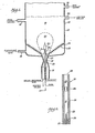
- Fig. 1 shows fluidized bed reactor 10 having containment vessel 11 with fluidized bed 19 supported on sloping bed support 14. Fluidization of the solid particles is maintained by fluidizing gas provided through fluidizing gas inlet 13 and passing through fluidizing gas jets 18 in fluidized bed support 14. Fluidized beds providing selective discharge of solid particles heavier than the average of the solid particles in the fluidized bed are known to the art. Solids discharge is controlled by passing a solids discharge gas upwardly through heavier solids discharge conduit 15 which has a necked region 16 and an opening 17 providing access from a lower portion of fluidized bed 19.
- the flow rate of solids discharge gas upwardly through the heavier solids discharge conduit necked region 16 is adjusted to permit the desired heavier solid particles to fall by gravity against the countercurrent gas flow through necked region 16 into the lower portion of heavier solids discharge conduit 15 while pushing the lighter solids upwardly and recirculating them to the fluidized bed, thereby providing the desired classification of particles.
- Suitable apparatus and processes for achieving the desired solid particle classification are known to the art, such as those taught by U.S. Patents 4,229,289; 3,935,825; and 2,906,608. Any of the fluidized bed apparatuses taught by these patents may be retrofitted or readily converted for use in the present invention.
- velocities of solids discharge gas upwardly through heavier solids discharge conduit necked region are about 4,5 to about 18 meter per second, preferably about 6 to about12 meter per second and velocities of fluidizing gas through fluidizing gas jets 18 are about 10 to about 30 meter per second, preferably about 12 to about 18 meter per second, providing a fluidizing gas velocity of about 0,3 to about 3 meter per second, dependent upon the density and particle size of the solids in the fluidized bed.
- the fluidizing gas injected through fluidizing gas jets 18 and/or the solids discharge gas injected through heavier solids discharge conduit 15 may be a reactant gas which may react with solids in the fluidized bed or with the fuel, such as additional oxidant gas, or it may be an inert gas solely for the purpose of solids fluidization and control of heavier solids discharge. Air is frequently used as both fluidizing gas and solids discharge gas.
- Prior fluidized beds have either used combustible solid particles or have been provided with combustible fuel generally throughout the fluidized bed to result in combustion throughout at least a large portion of the fluidized bed for generalized combustion and supply of desired reaction heat.
- Prior art fluidized beds have generally provided a relatively uniform temperature throughout the bed, or at least a gradual thermal gradient usually seeking to avoid differing temperature zones within the fluidized bed.
- An important aspect of the present invention is maintenance of two discrete temperature zones within a fluidized bed and to provide a localized discrete flame 45 above opening 17 of heavier solids discharge conduit 15 forming a higher temperature zone in flame 45 and surrounding volume 46.
- This higher temperature zone is at least about 40° to about 200°C, and preferably about 95° to about 150°C higher temperature than the remainderof the bed.
- Circulation of solids in the fluidized bed through and to the higher temperature region of flame 45 is increased by directing fluidizing gas jets 18 in such a manner as to direct particles in the fluidized bed toward flame 45.
- the solid particles may be passed through the higher temperature zone or through the flame itself several times for rapid heat up to higher temperatures.
- the jetting action of the upwards flowing solids discharge gas surrounding the flame aids in recirculation of solids through the higher temperature zone in and surrounding the flame facilitating more uniform reaction, such as more uniform size agglomerates.
- the discrete flame 45 is maintained within the fluidized bed by use of burner 30 extending through the central portion of heavier solids discharge conduit 15 and having its outlet 40 a short distance above heavier solids discharge conduit opening 17.
- Fig. 2 shows burner 30 in greater detail having burner housing 35 in which fluid fuel jet 31 with fuel orifice 33 is mounted by supports 34 to form annular oxidant passage 36. Downstream from fluid fuel jet orifice 33 burner housing 35 forms primary fuel/oxidant mixing chamber 37. Mixing orifice 38 is located at the downstream end of primary fuel/oxidant mixing chamber 37 and leads into secondary fuel/oxidant mixture mixing chamber 39 which extends to burner outlet 40. The secondary mixing chamber, downstream from the mixing orifice, establishes a uniform turbulent flow in the mixture before it enters the flame zone. The end of the gas inlet tube and the entrance and exit of the mixing orifice must be of tapered design to reduce formation of standing wakes which could cause ignition of the mixture.
- a discrete, stable flame may be maintained within the fluidized bed by any suitable means.
- the burner shown in Fig. 2 provides a discrete stable flame and may be operated with vaporized liquid or gaseous fuels as well known to the art.
- Any combustible fluid fuel may be used, such as vaporized fuel oil, natural gas, synthetic natural gas, medium Btu process gases, and other combustible gases.
- Natural gas is a typically preferred fuel.
- Suitable oxidants are well known to the art and include oxygen enriched gases and air. Thorough mixing of the fuel and oxidant is achieved by maintaining a ratio of fuel inlet velocity through fuel orifice 33 to the velocity of the oxidant introduced through annular oxidant passage 36 of about 5 to 10.
- Suitable fuel inlet velocities are in the order of about 30 to about 200 meter per second, preferably about'60 to about 150 meter per second, and suitable oxidant inlet velocities to primary fuel/oxidant mixing chamber 37 are about 6 to about 45 meter per second, preferably about 9 to about 30 meter per second.
- mixing orifice 38 increases the velocity of the fuel/oxidant mixture leaving primary mixing chamber 37 to about 30 to about 150 meter per second, preferably about 45 to about 90 meter per second.
- the velocity through the mixing orifice is about 3 to about 10 and more times the velocity in the primary mixing chamber, preferably about 3 to about 8 times.
- the accelerated, mixed fuel/oxidant mixture then passes through secondary mixing chamber 39 and passes through burner outlet 40 at a velocity of about 15 to about 60 meter per second, preferably about 18 to about 30 meter per second.
- the physical size of the burner components may vary with desired burner capacity and will be apparent in view of the parameters set out in this disclosure. These burner velocities together with the fluidizing gas and the solids discharge gas velocities as disclosed above, permit a discrete stable flame attached to the burner outlet 40.
- the fuel and oxidant may be preheated to a selected temperature dependent upon the fuel and oxidant used, for example, when using natural gas and air, generally the air is preheated to about 630° C Preheating may be achieved by any suitable method, such as thermal exchange with solids discharged from the process itself or by injection of steam.
- the fuel and the oxidant gas mix in the primary mixing chamber and the mixing orifice prevents flashback to the primary mixing chamber. This is due to the velocity through the mixing orifice being, preferably, about 3 to about 8 times the velocity in the primary mixing chamber.
- the discrete flame in the fluidized bed according to the apparatus and process of this invention provides formation of two temperature zones within a single fluidized bed improving the overall thermal efficiency and economics of many processes such as incineration of wastes, calcining of sand, roasting of ores, sintering of ores, concentration of ores, and the like, processes depending upon thermal treatment forming a heavier weight particle fraction of the solids in the fluidized bed.
- the temperature in the higher temperature zone in and surrounding the flame is about 720° to about 835°C while the temperature in the lower temperature zone encompassing the remainder of the fluidized bed is about 425° to about 615°C, dependent upon solids residence time in the fluidized bed and dependent upon the presence of inert heat transfer solids which may be added to the fluidized bed for enhanced heat transfer from the higher to the lower temperature zones of the fluidized bed.
- Feed solids to the fluidized bed may include any solids of particle size and nature which will maintain a fluidized bed and which with thermal and/or reactant gas treatment form a lighter weight gas and/or vapor and/or particle fraction and a heavier weight particle fraction, relative to the average bed contents.
- One process which is especially suited for the apparatus and process of the present invention is the sintering of fine particles of natural or concentrated iron ores for use as blast furnace feed for the production of iron and steel. It is most desirable to feed a blast furnace particles of a size of about 6 to 25 mm in diameter.
- Prior art sintering processes have achieved such sintering by depositing a mixture of iron ore, such as siderite (FeCO 3 ) fines and coke fines on a traveling grate.
- the traveling grate is shaped-similar to a conveyor belt forming a shallow trough with small holes in the bottom.
- the bed of materials on the grate is ignited by passing under an ignition burner that is fired with natural gas and air, and then as the grate moves slowly toward the discharge end, air is pulled down through the bed and as the coke fines burn in the bed, the siderite decomposes at about 425° Cto form iron oxide. As more coke burns, the heat generated increases the temperature of the entire mass to a temperature sufficient to sinter the iron oxide particles which are discharged and then crushed, cooled and screened to achieve the desired uniform feed size for the blast furnace. Fines produced in the process must be recycled.
- the process of the present invention integrates the decomposition of siderite to iron oxide and the production of controlled size agglomerates.
- iron ore fine particles may be fed directly to the lower temperature zone of a fluidized bed operated at a sufficiently high temperature (approximately 4250C) to convert the siderite to iron oxide.
- the higher temperature region in and surrounding the flame is operated at a temperature sufficiently high (approximately 725°0 ) to promote agglomeration of iron oxide formed in the lower temperature volume of the fluidized bed, the high velocity jetting action of the upward flowing solids discharge gas facilitating smoothening of the agglomerates.
- the size control of agglomerates disharged from the bottom of the bed is adjusted by the discharge gas velocity.
- the process of this invention in its application to production of blast furnace feed provides high process efficiency with continuous discharge of agglomerates ready for use as blast furnace feed.
- Another application of the process of this invention is the concentration of lower melting materials, such as copper, from higher melting impurities, such as sand or other oxides.
- copper ore such as chalcopyrite comprising a mixture of sulfides of copper, copper-iron and iron with gangue minerals, may be added directly to the lower temperature zone of a fluidized bed, the oxidant in the fluidizing gases removing sulfur by oxidation to sulfur dioxide.
- Iron would combine with silica, either from the gangue or added flux, in the higher temperature flame region of the fluidized bed and would be discharged as heavier weight agglomerates, while low sulfur, copper-rich material would be removed as lighter solids through lighter solids outlet 20 for copper refining processes.
- the solids waste material with no separation may be added to the fluidized bed where in the lower temperature portion, the combustible portions of the municipal solids waste will burn, and the higher temperature region and the discrete flame will provide agglomeration and discharge of non-organic components of the municipal solids waste.
- improved calcining may be achieved by virtue of the higher temperature region of the fluidized bed in the zone of the discrete flame.
- the apparatus and process of this invention has been used to burn off organic materials from used foundry sand to provide reusable clean foundry sands.
- the passage of contaminated solids through the higher temperature zone surrounding the discrete flame and multiple -passages through the flame itself provides rapid, thermally efficient separation of the organic materials by their gasification and removal through conduit 21.
- the sand being discharged is caused to undergo multiple passes through the higher temperature zone by the upward jetting action of solids discharge gas flowing upwardly through heavier solids discharge conduit 15 thereby assuring sand being discharged free from organic contaminants.
- the process and apparatus of this invention directly contrary to prior art fluidized beds, provide two temperature regions in a single fluidized bed.
- the apparatus and process of this invention by adjustment of the fluidizing gas jets may promote inward flow and recirculation of bed solids into and through the discrete flame enhancing rapid solids heating and providing additional fuel/oxidant mixing and enhancement of good combustion while the upward action of the solids discharge gas enhances multiple passage of the solids through the higher temperature region prior to discharge.
Landscapes
- Chemical & Material Sciences (AREA)
- Engineering & Computer Science (AREA)
- Combustion & Propulsion (AREA)
- Organic Chemistry (AREA)
- Chemical Kinetics & Catalysis (AREA)
- Dispersion Chemistry (AREA)
- Mechanical Engineering (AREA)
- General Engineering & Computer Science (AREA)
- Fluidized-Bed Combustion And Resonant Combustion (AREA)
- Devices And Processes Conducted In The Presence Of Fluids And Solid Particles (AREA)
- Crucibles And Fluidized-Bed Furnaces (AREA)
Applications Claiming Priority (2)
| Application Number | Priority Date | Filing Date | Title |
|---|---|---|---|
| US862325 | 1986-05-12 | ||
| US06/862,325 US4693682A (en) | 1986-05-12 | 1986-05-12 | Treatment of solids in fluidized bed burner |
Publications (2)
| Publication Number | Publication Date |
|---|---|
| EP0246191A2 true EP0246191A2 (de) | 1987-11-19 |
| EP0246191A3 EP0246191A3 (de) | 1990-06-20 |
Family
ID=25338221
Family Applications (1)
| Application Number | Title | Priority Date | Filing Date |
|---|---|---|---|
| EP87810289A Withdrawn EP0246191A3 (de) | 1986-05-12 | 1987-05-08 | Behandlung fester Teilchen in einer Wirbelschicht mit Brenner |
Country Status (4)
| Country | Link |
|---|---|
| US (1) | US4693682A (de) |
| EP (1) | EP0246191A3 (de) |
| JP (1) | JPS62284187A (de) |
| CA (1) | CA1262049A (de) |
Cited By (6)
| Publication number | Priority date | Publication date | Assignee | Title |
|---|---|---|---|---|
| DE10260737A1 (de) * | 2002-12-23 | 2004-07-15 | Outokumpu Oyj | Verfahren und Anlage zur Wärmebehandlung von titanhaltigen Feststoffen |
| DE10260735A1 (de) * | 2002-12-23 | 2004-07-15 | Outokumpu Oyj | Verfahren und Anlage zur Wärmebehandlung von sulfidischen Erzen |
| US7625422B2 (en) | 2002-12-23 | 2009-12-01 | Outotec Oyj | Method and plant for the heat treatment of solids containing iron oxide using a fluidized bed reactor |
| US7632334B2 (en) | 2002-12-23 | 2009-12-15 | Outotec Oyj | Method and plant for the heat treatment of solids containing iron oxide |
| US7803268B2 (en) | 2002-12-23 | 2010-09-28 | Outotec Oyj | Method and plant for producing low-temperature coke |
| US7854608B2 (en) | 2002-12-23 | 2010-12-21 | Outotec Oyj | Method and apparatus for heat treatment in a fluidized bed |
Families Citing this family (16)
| Publication number | Priority date | Publication date | Assignee | Title |
|---|---|---|---|---|
| JPS62200105A (ja) * | 1986-02-27 | 1987-09-03 | Yoji Honda | 焼却炉 |
| CA1285761C (en) * | 1986-04-01 | 1991-07-09 | Kawasaki Jukogyo Kabushiki Kaisha | Plant for manufacturing cement clinker |
| DE3725512A1 (de) * | 1987-07-29 | 1989-02-09 | Kettenbauer Gmbh & Co Verfahre | Schwebegas-reaktor |
| US4969404A (en) * | 1989-04-21 | 1990-11-13 | Dorr-Oliver Incorporated | Ash classifier-cooler-combustor |
| US5165888A (en) * | 1990-02-08 | 1992-11-24 | Rothschild John J | Gravity flow thermal process for reclaiming foundry sand |
| US5110288A (en) * | 1990-02-08 | 1992-05-05 | Rothschild John J | Gravity flow thermal process for reclaiming foundry sand |
| US5060584A (en) * | 1990-06-22 | 1991-10-29 | Energy Products Of Idaho | Fluidized bed combustion |
| US5101742A (en) * | 1990-06-22 | 1992-04-07 | Energy Products Of Idaho | Fluidized bed combustion |
| US5158449A (en) * | 1991-01-08 | 1992-10-27 | Institute Of Gas Technology | Thermal ash agglomeration process |
| US5143486A (en) * | 1991-03-01 | 1992-09-01 | Riley Stoker Corporation | Flow promoter for fluidized solids |
| GB2263535B (en) * | 1992-01-08 | 1995-07-12 | Richards Eng Ltd | Incineration apparatus |
| FR2784602B1 (fr) * | 1998-10-20 | 2002-04-12 | Eurecat Europ Retrait Catalys | Procede de traitement d'un catalyseur ou d'un adsorbant en lit fluidise |
| DE10260739B3 (de) | 2002-12-23 | 2004-09-16 | Outokumpu Oy | Verfahren und Anlage zur Herstellung von Metalloxid aus Metallverbindungen |
| US9272912B2 (en) | 2006-08-25 | 2016-03-01 | Robert A. Rossi | Process and system for producing commercial quality carbon dioxide from recausticizing process calcium carbonates |
| US20090114352A1 (en) * | 2006-08-25 | 2009-05-07 | Rossi Robert A | Process and system for calcination of high solids kraft paper pulp mill lime mud |
| ZA201801735B (en) * | 2018-03-14 | 2019-01-30 | Traxys Brix Pty Ltd | Sinter wessel technology |
Family Cites Families (18)
| Publication number | Priority date | Publication date | Assignee | Title |
|---|---|---|---|---|
| DD63611A (de) * | ||||
| BE554203A (de) * | 1956-01-19 | |||
| US3417978A (en) * | 1965-09-17 | 1968-12-24 | Ube Industries | Method and apparatus for the gasification and combustion of liquid fuel in a fluidized bed |
| US3954390A (en) * | 1974-06-28 | 1976-05-04 | Akhundov Alizakir Alikhady Ogl | Method for producing aggregate used in hardening compositions, predominantly concretes, a fluidized-bed kiln for calcining mineral stock by means of same method, and an aggregate produced by same method |
| US3935825A (en) * | 1975-02-24 | 1976-02-03 | Institute Of Gas Technology | Coal ash agglomeration device |
| US4017253A (en) * | 1975-09-16 | 1977-04-12 | The United States Of America As Represented By The United States Energy Research And Development Administration | Fluidized-bed calciner with combustion nozzle and shroud |
| GB1589566A (en) * | 1976-09-08 | 1981-05-13 | British Petroleum Co | Nozzle arrangement suitable for a fluidised bed furnace |
| US4102277A (en) * | 1977-01-03 | 1978-07-25 | Dorr-Oliver Incorporated | Incineration of lime-conditioned sewage sludge with high sulfur fuel |
| US4308806A (en) * | 1978-04-05 | 1982-01-05 | Babcock-Hitachi Kabushiki Kaisha | Incinerator for burning waste and a method of utilizing same |
| EP0008187B1 (de) * | 1978-08-04 | 1983-04-27 | The British Petroleum Company p.l.c. | Einspritzdüse und damit versehene Verteilerplatte |
| US4265615A (en) * | 1978-12-11 | 1981-05-05 | United Technologies Corporation | Fuel injection system for low emission burners |
| US4229289A (en) * | 1979-03-12 | 1980-10-21 | Institute Of Gas Technology | Fluidized bed apparatus and process |
| ZA801294B (en) * | 1979-03-14 | 1981-10-28 | British Petroleum Co | Fluidised bed combustor |
| JPS5620455A (en) * | 1979-07-31 | 1981-02-26 | Matsushita Electric Works Ltd | Air massager |
| US4400150A (en) * | 1980-10-20 | 1983-08-23 | Stone-Platt Fluidfire Limited | Fluidized bed combustor distributor plate assembly |
| US4493636A (en) * | 1981-03-05 | 1985-01-15 | The United States Of America As Represented By The United States Department Of Energy | Gasification system |
| JPS5839786A (ja) * | 1981-08-31 | 1983-03-08 | Chiyoda Kagaku Kenkyusho:Kk | 鉄系金属の防錆剤 |
| US4424766A (en) * | 1982-09-09 | 1984-01-10 | Boyle Bede Alfred | Hydro/pressurized fluidized bed combustor |
-
1986
- 1986-05-12 US US06/862,325 patent/US4693682A/en not_active Expired - Lifetime
-
1987
- 1987-05-08 EP EP87810289A patent/EP0246191A3/de not_active Withdrawn
- 1987-05-11 CA CA000536739A patent/CA1262049A/en not_active Expired
- 1987-05-12 JP JP62115711A patent/JPS62284187A/ja active Pending
Cited By (12)
| Publication number | Priority date | Publication date | Assignee | Title |
|---|---|---|---|---|
| DE10260737A1 (de) * | 2002-12-23 | 2004-07-15 | Outokumpu Oyj | Verfahren und Anlage zur Wärmebehandlung von titanhaltigen Feststoffen |
| DE10260735A1 (de) * | 2002-12-23 | 2004-07-15 | Outokumpu Oyj | Verfahren und Anlage zur Wärmebehandlung von sulfidischen Erzen |
| DE10260737B4 (de) * | 2002-12-23 | 2005-06-30 | Outokumpu Oyj | Verfahren und Anlage zur Wärmebehandlung von titanhaltigen Feststoffen |
| DE10260735B4 (de) * | 2002-12-23 | 2005-07-14 | Outokumpu Oyj | Verfahren und Anlage zur Wärmebehandlung von sulfidischen Erzen |
| US7625422B2 (en) | 2002-12-23 | 2009-12-01 | Outotec Oyj | Method and plant for the heat treatment of solids containing iron oxide using a fluidized bed reactor |
| US7632334B2 (en) | 2002-12-23 | 2009-12-15 | Outotec Oyj | Method and plant for the heat treatment of solids containing iron oxide |
| US7651547B2 (en) | 2002-12-23 | 2010-01-26 | Outotec Oyj | Fluidized bed method and plant for the heat treatment of solids containing titanium |
| US7803268B2 (en) | 2002-12-23 | 2010-09-28 | Outotec Oyj | Method and plant for producing low-temperature coke |
| US7854608B2 (en) | 2002-12-23 | 2010-12-21 | Outotec Oyj | Method and apparatus for heat treatment in a fluidized bed |
| US8021600B2 (en) | 2002-12-23 | 2011-09-20 | Outotec Oyj | Method and plant for the heat treatment of solids containing iron oxide |
| US8021601B2 (en) | 2002-12-23 | 2011-09-20 | Outotec Oyj | Plant for the heat treatment of solids containing titanium |
| US8025836B2 (en) | 2002-12-23 | 2011-09-27 | Outotec Oyi | Method and plant for the heat treatment of solids containing iron oxide |
Also Published As
| Publication number | Publication date |
|---|---|
| JPS62284187A (ja) | 1987-12-10 |
| CA1262049A (en) | 1989-10-03 |
| EP0246191A3 (de) | 1990-06-20 |
| US4693682A (en) | 1987-09-15 |
Similar Documents
| Publication | Publication Date | Title |
|---|---|---|
| US4693682A (en) | Treatment of solids in fluidized bed burner | |
| US4508040A (en) | Method and plant for conversion of waste material to stable final products | |
| US4684375A (en) | Method for gasifying a material using a circulating fluidized bed | |
| KR930004475B1 (ko) | 금속 산화물을 함유한 물질의 환원방법 및 장치 | |
| CN103502400B (zh) | 用于产生合成气的增强型等离子体气化器 | |
| JPS6013401B2 (ja) | 液状銑鉄及び還元ガスを発生させる方法及び装置 | |
| JPH0143799B2 (de) | ||
| KR100241616B1 (ko) | 용융 선철 또는 강 시제품의 제조방법 및 이를 수행하기 위한 플랜트 | |
| KR20130109991A (ko) | 화학적 순환식 연소 루프용 입자 분리 장치 | |
| JP5124073B2 (ja) | コバルト回収量の改良された鉄分に富むニッケル高含有マット製造用ニッケルマット連続転炉 | |
| US5006062A (en) | Treatment of solids in fluidized bed burner | |
| US4565139A (en) | Method and apparatus for obtaining energy | |
| US4291635A (en) | Apparatus for feeding fluidized bed incinerator, and method of autogenic operation of same | |
| US4969404A (en) | Ash classifier-cooler-combustor | |
| KR100641967B1 (ko) | 용융 선철 또는 1차 강 제품을 제조하는 방법 및 장치 | |
| US3119379A (en) | Apparatus for combustion of fuels | |
| KR100240810B1 (ko) | 용융선철 또는 강 시제품의 제조방법 및 이를 수행하기 위한 플랜트 | |
| US5158449A (en) | Thermal ash agglomeration process | |
| US3945810A (en) | Apparatus for disposal of plastics | |
| US5625119A (en) | Method for treating sludge and soil contaminated with hydrocarbons | |
| US5118288A (en) | Cement advanced furnace and process | |
| US5188668A (en) | Cement advanced furnace and process | |
| EP0059757B1 (de) | Vorrichtung zur kontinuierlichen verbrennung von teilchen in einem luftstrom in einem senkrechten ofen | |
| RU2323260C2 (ru) | Способ получения металлов, имеющих низкую температуру испарения | |
| CZ422098A3 (cs) | Tavící generátor pro výrobu roztaveného kovu |
Legal Events
| Date | Code | Title | Description |
|---|---|---|---|
| PUAI | Public reference made under article 153(3) epc to a published international application that has entered the european phase |
Free format text: ORIGINAL CODE: 0009012 |
|
| AK | Designated contracting states |
Kind code of ref document: A2 Designated state(s): BE DE FR GB IT LU NL SE |
|
| PUAL | Search report despatched |
Free format text: ORIGINAL CODE: 0009013 |
|
| AK | Designated contracting states |
Kind code of ref document: A3 Designated state(s): BE DE FR GB IT LU NL SE |
|
| 17P | Request for examination filed |
Effective date: 19900809 |
|
| 17Q | First examination report despatched |
Effective date: 19910725 |
|
| STAA | Information on the status of an ep patent application or granted ep patent |
Free format text: STATUS: THE APPLICATION IS DEEMED TO BE WITHDRAWN |
|
| 18D | Application deemed to be withdrawn |
Effective date: 19930501 |
|
| RIN1 | Information on inventor provided before grant (corrected) |
Inventor name: LEE, BERNARD S. Inventor name: PUNWANI, DHARAM V. Inventor name: TARMAN, PAUL S. |