EP0246405A1 - Robinetterie sanitaire - Google Patents
Robinetterie sanitaire Download PDFInfo
- Publication number
- EP0246405A1 EP0246405A1 EP87103400A EP87103400A EP0246405A1 EP 0246405 A1 EP0246405 A1 EP 0246405A1 EP 87103400 A EP87103400 A EP 87103400A EP 87103400 A EP87103400 A EP 87103400A EP 0246405 A1 EP0246405 A1 EP 0246405A1
- Authority
- EP
- European Patent Office
- Prior art keywords
- control valve
- opening
- flow control
- valve according
- water
- Prior art date
- Legal status (The legal status is an assumption and is not a legal conclusion. Google has not performed a legal analysis and makes no representation as to the accuracy of the status listed.)
- Granted
Links
- XLYOFNOQVPJJNP-UHFFFAOYSA-N water Substances O XLYOFNOQVPJJNP-UHFFFAOYSA-N 0.000 claims abstract description 43
- 238000009434 installation Methods 0.000 claims abstract description 13
- 230000001105 regulatory effect Effects 0.000 claims description 17
- 238000011144 upstream manufacturing Methods 0.000 abstract description 4
- 239000007787 solid Substances 0.000 abstract 4
- 238000010276 construction Methods 0.000 description 2
- 229910010293 ceramic material Inorganic materials 0.000 description 1
- 238000003754 machining Methods 0.000 description 1
- 238000004519 manufacturing process Methods 0.000 description 1
- 230000004048 modification Effects 0.000 description 1
- 238000012986 modification Methods 0.000 description 1
- 239000008399 tap water Substances 0.000 description 1
- 235000020679 tap water Nutrition 0.000 description 1
Images
Classifications
-
- F—MECHANICAL ENGINEERING; LIGHTING; HEATING; WEAPONS; BLASTING
- F16—ENGINEERING ELEMENTS AND UNITS; GENERAL MEASURES FOR PRODUCING AND MAINTAINING EFFECTIVE FUNCTIONING OF MACHINES OR INSTALLATIONS; THERMAL INSULATION IN GENERAL
- F16K—VALVES; TAPS; COCKS; ACTUATING-FLOATS; DEVICES FOR VENTING OR AERATING
- F16K11/00—Multiple-way valves, e.g. mixing valves; Pipe fittings incorporating such valves
- F16K11/02—Multiple-way valves, e.g. mixing valves; Pipe fittings incorporating such valves with all movable sealing faces moving as one unit
- F16K11/06—Multiple-way valves, e.g. mixing valves; Pipe fittings incorporating such valves with all movable sealing faces moving as one unit comprising only sliding valves, i.e. sliding closure elements
- F16K11/078—Multiple-way valves, e.g. mixing valves; Pipe fittings incorporating such valves with all movable sealing faces moving as one unit comprising only sliding valves, i.e. sliding closure elements with pivoted and linearly movable closure members
- F16K11/0782—Single-lever operated mixing valves with closure members having flat sealing faces
- F16K11/0787—Single-lever operated mixing valves with closure members having flat sealing faces with both the supply and the discharge passages being on the same side of the closure members
Definitions
- the invention relates to a flow control valve with the features specified in the preamble of claim 1.
- valves are used as mixing valves in sanitary fittings, with the actuator being able to set the water flow rate in a first degree of freedom and the mixing ratio of the incoming cold and hot water or the temperature of the exiting mixed water in a second degree of freedom.
- the invention has for its object to provide a valve with simple means with which a sensitive adjustment of the total flow or water supply and an optional connection or switching of inlet or outlet openings is possible.
- the invention offers the possibility of combining the sensitive quantity regulation with an optional switchover to, for example, two different maximum flow rates per time unit (normal position - economy position) or cold water can also be added to the incoming mixed water.
- the quantity regulating valve according to the invention can advantageously be arranged in the factory together with an upstream thermostatic mixing valve in an installation housing, as a result of which the installation on the construction site can be considerably simplified.
- the mixing valve with the temperature selection device and the quantity regulating valve with the actuating device are each expedient as a separate structural unit trained, which can be used and held separately at corresponding locations of the installation housing.
- the quantity control valve according to the invention thus offers increased user comfort with a high level of functional reliability and a long service life, a relatively simple installation on the construction site, in the bathroom, etc. being made possible.
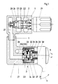
- an installation housing 1 shown schematically, is provided, in which a thermostatically controlled mixing valve 2 with a temperature selection device 21 and a quantity regulating valve 3 with an actuating handle 31 are arranged as a separate structural unit.
- a thermostatically controlled mixing valve 2 with a temperature selection device 21 and a quantity regulating valve 3 with an actuating handle 31 are arranged as a separate structural unit.
- connections for the cold water and hot water supply lines are provided on the installation housing 1 and are connected to annular chambers 22, 23 for the cold and warm water.
- the incoming cold and hot water is mixed by a double seat valve slide 25, which is connected to the temperature selection device 21 via an expansion element 24, to tempered water in a mixing chamber 26 and from here into a mixed water channel 27 of the installation housing 1 delivered, from where the tempered mixed water is fed to the flow control valve 3.
- the flow control valve 3 is encapsulated in a cartridge housing 32 and connected in a sealed manner to the inflow and outflow channels formed in the installation housing 1.
- a fixed disk 33 with an inlet opening 331 and two outlet openings 332, 333 in the form of a ring segment for one Bathtub water inlet and a water inlet for a shower provided.
- a regulating disk 34 with an overflow channel 341 for the incoming mixed water is attached to the fixed disk 33, which is held stationary in the cartridge housing 32.
- Both disks, fixed disk 33 and regulating disk 34 are made of a wear-resistant ceramic material and lie watertight against one another with their end faces, which have been smoothed by appropriate fine machining.
- the overflow channel 341 is formed in the regulating disk 34 as a smooth opening and is closed on the outer end face by a closure cap 35, which at the same time is positively connected to the regulating disk 34.
- the closure cap 35 On the opposite side of the slide, the closure cap 35 bears against a rotatable but axially fixed bush 37 for support.
- a double-armed adjusting lever 36 is arranged in the socket 37 on an axis of rotation 38, which on the one hand can be rotated together with the socket 37 about the axis of rotation 38 and on the other hand can be deflected about a pivot axis 39 lying perpendicular to the axis of rotation 38.
- the adjusting lever 36 is connected on the one hand to the closure cap 35 and on the other hand to the actuating handle 31.
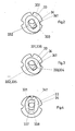
- the regulating disk 34 experiences a radial deflection to the fixed disk 33, as a result of which the inlet opening 331 can be connected to at least one outlet opening 332, 333 depending on the pivot position. With this actuating movement, the total flow rate or the tap water quantity per unit of time can be determined sensitively. If, on the other hand, the actuating handle 31 is rotated in the direction of an arrow 5 about the axis of rotation 38, the regulating disk 34 experiences, as in particular the drawing in FIG. 2 (Schematic top view of the superimposed fixed disc 33 and regulating disc 34) can be seen, a rotation to the fixed disc 33.
- FIG. 3 Another exemplary embodiment is shown in FIG. 3, the two valve disks, fixed disk 33 and regulating disk 34, being shown lying one on top of the other in a schematic illustration in plan view.
- the dimensions of the two disks correspond to the dimensions of the exemplary embodiment according to FIG. 2.
- a mixed water inlet 334 is connected to the ring segment-like opening 333 and a further cold water inlet 335 is connected to the opening 332, the opening 331 being a drain 336 is switched and is connected to a Kneipp shower, for example.
- the quantity can be regulated in the same way by pivoting the actuating handle 31, while when rotating in the direction of an arrow 5, either the mixed water outlet or the cold water outlet can be connected to the Kneipp shower is.
- FIG. 4 shows a further embodiment of the quantity regulating valve in a schematic manner.
- the mixed water is brought up in the same way as in the exemplary embodiment according to FIG. 2 through an opening 331.
- Two differently sized ring segment-like openings 337 and 338 are formed for the mixed water outlet.
- the opening 337 has a cross section, as is required for the nominal flow rate of the volume control valve, while the opening 338 is substantially reduced in cross section, which can be switched from normal to economy mode and vice versa by means of a rotary movement in the direction of an arrow 5.
- the quantity regulating valve 3 according to the invention with the thermostatically controlled mixing valve 2 is arranged in an installation housing 1, the mixed water generated being in a channel 27 and possibly a further channel for the feed of separate cold water are fed directly to the quantity regulating valve 3 and are formed in the outlet channels 28 with corresponding connection points for supply to the consumers.
- the flow control valve can also be installed separately on the building wall or on a sanitary unit and connected to a mixed water production device via corresponding pipelines.
Landscapes
- Engineering & Computer Science (AREA)
- General Engineering & Computer Science (AREA)
- Mechanical Engineering (AREA)
- Multiple-Way Valves (AREA)
- Domestic Plumbing Installations (AREA)
Applications Claiming Priority (2)
| Application Number | Priority Date | Filing Date | Title |
|---|---|---|---|
| DE19863609771 DE3609771A1 (de) | 1986-03-22 | 1986-03-22 | Mengenregulierventil |
| DE3609771 | 1986-03-22 |
Publications (2)
| Publication Number | Publication Date |
|---|---|
| EP0246405A1 true EP0246405A1 (fr) | 1987-11-25 |
| EP0246405B1 EP0246405B1 (fr) | 1990-05-09 |
Family
ID=6297067
Family Applications (1)
| Application Number | Title | Priority Date | Filing Date |
|---|---|---|---|
| EP87103400A Expired - Lifetime EP0246405B1 (fr) | 1986-03-22 | 1987-03-10 | Robinetterie sanitaire |
Country Status (4)
| Country | Link |
|---|---|
| EP (1) | EP0246405B1 (fr) |
| DE (2) | DE3609771A1 (fr) |
| DK (1) | DK164237C (fr) |
| ES (1) | ES2015904B3 (fr) |
Cited By (3)
| Publication number | Priority date | Publication date | Assignee | Title |
|---|---|---|---|---|
| DE19640509A1 (de) * | 1996-10-01 | 1998-04-02 | Grohe Kg Hans | Sanitärarmatur |
| DE19702038A1 (de) * | 1997-01-22 | 1998-07-23 | Grohe Kg Hans | Sanitärarmatur |
| WO2012089069A1 (fr) * | 2010-12-29 | 2012-07-05 | 厦门松霖科技有限公司 | Obturateur destiné à commuter des passages d'eau et à réguler le débit d'eau |
Families Citing this family (1)
| Publication number | Priority date | Publication date | Assignee | Title |
|---|---|---|---|---|
| DE202008012727U1 (de) * | 2008-09-24 | 2010-02-25 | Viega Gmbh & Co. Kg | Elektronisch steuerbare Armatur zum Mischen von kaltem und warmem Wasser, insbesondere für einen Waschtisch |
Citations (6)
| Publication number | Priority date | Publication date | Assignee | Title |
|---|---|---|---|---|
| DE2014552A1 (de) * | 1970-03-26 | 1971-12-02 | Grohe Armaturen Friedrich | Thermostat-Mischventil |
| US3929283A (en) * | 1973-11-13 | 1975-12-30 | Fonderie Soc Gen De | Thermostatic mixing apparatus and a related method for regulating temperature |
| DE2653754B2 (de) * | 1976-11-26 | 1978-09-07 | Willi 8225 Traunreuth Schaer | Wannenfüll- und Brausebatterie |
| FR2483036A1 (fr) * | 1980-05-20 | 1981-11-27 | Willi Anton | Melangeur eau froide-eau chaude commande par un thermostat |
| DE3244121A1 (de) * | 1982-11-29 | 1984-05-30 | Friedrich Grohe Armaturenfabrik Gmbh & Co, 5870 Hemer | Sanitaermischventil |
| CH648390A5 (en) * | 1980-05-12 | 1985-03-15 | Anton J Willi | Thermostatically regulated mixing valve for cold and hot water |
-
1986
- 1986-03-22 DE DE19863609771 patent/DE3609771A1/de not_active Withdrawn
-
1987
- 1987-03-10 ES ES87103400T patent/ES2015904B3/es not_active Expired - Lifetime
- 1987-03-10 DE DE8787103400T patent/DE3762677D1/de not_active Expired - Lifetime
- 1987-03-10 EP EP87103400A patent/EP0246405B1/fr not_active Expired - Lifetime
- 1987-03-20 DK DK143187A patent/DK164237C/da not_active IP Right Cessation
Patent Citations (6)
| Publication number | Priority date | Publication date | Assignee | Title |
|---|---|---|---|---|
| DE2014552A1 (de) * | 1970-03-26 | 1971-12-02 | Grohe Armaturen Friedrich | Thermostat-Mischventil |
| US3929283A (en) * | 1973-11-13 | 1975-12-30 | Fonderie Soc Gen De | Thermostatic mixing apparatus and a related method for regulating temperature |
| DE2653754B2 (de) * | 1976-11-26 | 1978-09-07 | Willi 8225 Traunreuth Schaer | Wannenfüll- und Brausebatterie |
| CH648390A5 (en) * | 1980-05-12 | 1985-03-15 | Anton J Willi | Thermostatically regulated mixing valve for cold and hot water |
| FR2483036A1 (fr) * | 1980-05-20 | 1981-11-27 | Willi Anton | Melangeur eau froide-eau chaude commande par un thermostat |
| DE3244121A1 (de) * | 1982-11-29 | 1984-05-30 | Friedrich Grohe Armaturenfabrik Gmbh & Co, 5870 Hemer | Sanitaermischventil |
Cited By (8)
| Publication number | Priority date | Publication date | Assignee | Title |
|---|---|---|---|---|
| DE19640509A1 (de) * | 1996-10-01 | 1998-04-02 | Grohe Kg Hans | Sanitärarmatur |
| EP0834691A2 (fr) | 1996-10-01 | 1998-04-08 | Hans Grohe GmbH & Co. KG | Robinet sanitaire |
| EP0834691A3 (fr) * | 1996-10-01 | 1998-09-23 | Hans Grohe GmbH & Co. KG | Robinet sanitaire |
| US5960828A (en) * | 1996-10-01 | 1999-10-05 | Hans Grohe Gmbh & Co. Kg | Sanitary fitting |
| DE19702038A1 (de) * | 1997-01-22 | 1998-07-23 | Grohe Kg Hans | Sanitärarmatur |
| EP0855635A1 (fr) | 1997-01-22 | 1998-07-29 | Hans Grohe GmbH & Co. KG | Robinetterie sanitaire |
| WO2012089069A1 (fr) * | 2010-12-29 | 2012-07-05 | 厦门松霖科技有限公司 | Obturateur destiné à commuter des passages d'eau et à réguler le débit d'eau |
| US9222586B2 (en) | 2010-12-29 | 2015-12-29 | Xiamen Solex High-Tech Industries Co., Ltd. | Valve for switching waterways and adjusting flow |
Also Published As
| Publication number | Publication date |
|---|---|
| DE3762677D1 (de) | 1990-06-13 |
| EP0246405B1 (fr) | 1990-05-09 |
| DK143187A (da) | 1987-09-23 |
| DK143187D0 (da) | 1987-03-20 |
| DE3609771A1 (de) | 1987-09-24 |
| DK164237C (da) | 1992-11-02 |
| ES2015904B3 (es) | 1990-09-16 |
| DK164237B (da) | 1992-05-25 |
Similar Documents
| Publication | Publication Date | Title |
|---|---|---|
| EP0242675B1 (fr) | Vanne mélangeuse | |
| EP0162342B1 (fr) | Insert de contrôle pour mélangeur sanitaire | |
| EP0110339B1 (fr) | Mitigeur sanitaire | |
| EP0844423B1 (fr) | Mitigeur à monocommande. | |
| EP0605845B1 (fr) | Cartouche pour un robinet mélangeur | |
| DE3525052C2 (fr) | ||
| DE4308994C1 (de) | Sanitäres Mischventil | |
| DE2349772A1 (de) | Absperrorgan | |
| DE19640509A1 (de) | Sanitärarmatur | |
| EP0392441B1 (fr) | Armature d'arrêt à mixture | |
| EP1576307B1 (fr) | Robinetterie sanitaire d'ecoulement | |
| EP0653581B1 (fr) | Robinet mitigeur et d'arrêt | |
| DE2735544A1 (de) | Steuerscheibensatz fuer eine mischbatterie sowie einen derartigen steuerscheibensatz enthaltende mischbatterie | |
| DE3338063A1 (de) | Sanitaere wasserausgabeeinrichtung mit heisswasserbereiter und zapfvorrichtung | |
| EP0246405B1 (fr) | Robinetterie sanitaire | |
| DE3518698C2 (de) | Mischventil | |
| DE19716307A1 (de) | Thermostatgeregeltes Mischventil | |
| DE3113653A1 (de) | Mischbatterie | |
| DE2264815A1 (de) | Mischbatterie | |
| EP3859483B1 (fr) | Armature de mitigeur pourvu de soupape thermostatique compacte | |
| DE68922114T2 (de) | Mischventil mit kugelsteuerungsmechanik. | |
| DE2911965C2 (de) | Mischventil | |
| AT410705B (de) | Misch- und absperrventil | |
| EP1647747B1 (fr) | Robinet mitigeur | |
| DE2937474C2 (de) | Überlauf-Mischbatterie |
Legal Events
| Date | Code | Title | Description |
|---|---|---|---|
| PUAI | Public reference made under article 153(3) epc to a published international application that has entered the european phase |
Free format text: ORIGINAL CODE: 0009012 |
|
| AK | Designated contracting states |
Kind code of ref document: A1 Designated state(s): DE ES FR GB NL SE |
|
| 17P | Request for examination filed |
Effective date: 19880411 |
|
| 17Q | First examination report despatched |
Effective date: 19890420 |
|
| GRAA | (expected) grant |
Free format text: ORIGINAL CODE: 0009210 |
|
| AK | Designated contracting states |
Kind code of ref document: B1 Designated state(s): DE ES FR GB NL SE |
|
| REF | Corresponds to: |
Ref document number: 3762677 Country of ref document: DE Date of ref document: 19900613 |
|
| ET | Fr: translation filed | ||
| GBT | Gb: translation of ep patent filed (gb section 77(6)(a)/1977) | ||
| PLBE | No opposition filed within time limit |
Free format text: ORIGINAL CODE: 0009261 |
|
| STAA | Information on the status of an ep patent application or granted ep patent |
Free format text: STATUS: NO OPPOSITION FILED WITHIN TIME LIMIT |
|
| 26N | No opposition filed | ||
| REG | Reference to a national code |
Ref country code: FR Ref legal event code: CN |
|
| REG | Reference to a national code |
Ref country code: GB Ref legal event code: 732 |
|
| REG | Reference to a national code |
Ref country code: ES Ref legal event code: PC2A Owner name: FRIEDRICH GROHE AKTIENGESELLSCHAFT |
|
| PGFP | Annual fee paid to national office [announced via postgrant information from national office to epo] |
Ref country code: NL Payment date: 19940331 Year of fee payment: 8 |
|
| EAL | Se: european patent in force in sweden |
Ref document number: 87103400.5 |
|
| PG25 | Lapsed in a contracting state [announced via postgrant information from national office to epo] |
Ref country code: NL Effective date: 19951001 |
|
| NLV4 | Nl: lapsed or anulled due to non-payment of the annual fee |
Effective date: 19951001 |
|
| PGFP | Annual fee paid to national office [announced via postgrant information from national office to epo] |
Ref country code: SE Payment date: 19970212 Year of fee payment: 11 |
|
| PG25 | Lapsed in a contracting state [announced via postgrant information from national office to epo] |
Ref country code: SE Free format text: LAPSE BECAUSE OF NON-PAYMENT OF DUE FEES Effective date: 19980311 |
|
| EUG | Se: european patent has lapsed |
Ref document number: 87103400.5 |
|
| REG | Reference to a national code |
Ref country code: FR Ref legal event code: CJ |
|
| REG | Reference to a national code |
Ref country code: GB Ref legal event code: IF02 |
|
| PGFP | Annual fee paid to national office [announced via postgrant information from national office to epo] |
Ref country code: GB Payment date: 20030305 Year of fee payment: 17 |
|
| PGFP | Annual fee paid to national office [announced via postgrant information from national office to epo] |
Ref country code: DE Payment date: 20030324 Year of fee payment: 17 |
|
| PGFP | Annual fee paid to national office [announced via postgrant information from national office to epo] |
Ref country code: FR Payment date: 20030328 Year of fee payment: 17 Ref country code: ES Payment date: 20030328 Year of fee payment: 17 |
|
| PG25 | Lapsed in a contracting state [announced via postgrant information from national office to epo] |
Ref country code: GB Free format text: LAPSE BECAUSE OF NON-PAYMENT OF DUE FEES Effective date: 20040310 |
|
| PG25 | Lapsed in a contracting state [announced via postgrant information from national office to epo] |
Ref country code: ES Free format text: LAPSE BECAUSE OF NON-PAYMENT OF DUE FEES Effective date: 20040311 |
|
| REG | Reference to a national code |
Ref country code: ES Ref legal event code: PC2A |
|
| PG25 | Lapsed in a contracting state [announced via postgrant information from national office to epo] |
Ref country code: DE Free format text: LAPSE BECAUSE OF NON-PAYMENT OF DUE FEES Effective date: 20041001 |
|
| GBPC | Gb: european patent ceased through non-payment of renewal fee |
Effective date: 20040310 |
|
| PG25 | Lapsed in a contracting state [announced via postgrant information from national office to epo] |
Ref country code: FR Free format text: LAPSE BECAUSE OF NON-PAYMENT OF DUE FEES Effective date: 20041130 |
|
| REG | Reference to a national code |
Ref country code: FR Ref legal event code: ST |
|
| REG | Reference to a national code |
Ref country code: ES Ref legal event code: FD2A Effective date: 20040311 |