EP0246437A2 - Machine, par exemple raboteuse de plaques - Google Patents
Machine, par exemple raboteuse de plaques Download PDFInfo
- Publication number
- EP0246437A2 EP0246437A2 EP87105023A EP87105023A EP0246437A2 EP 0246437 A2 EP0246437 A2 EP 0246437A2 EP 87105023 A EP87105023 A EP 87105023A EP 87105023 A EP87105023 A EP 87105023A EP 0246437 A2 EP0246437 A2 EP 0246437A2
- Authority
- EP
- European Patent Office
- Prior art keywords
- bearing
- cutter head
- machine according
- carrier
- journal
- Prior art date
- Legal status (The legal status is an assumption and is not a legal conclusion. Google has not performed a legal analysis and makes no representation as to the accuracy of the status listed.)
- Withdrawn
Links
Images


Classifications
-
- B—PERFORMING OPERATIONS; TRANSPORTING
- B23—MACHINE TOOLS; METAL-WORKING NOT OTHERWISE PROVIDED FOR
- B23D—PLANING; SLOTTING; SHEARING; BROACHING; SAWING; FILING; SCRAPING; LIKE OPERATIONS FOR WORKING METAL BY REMOVING MATERIAL, NOT OTHERWISE PROVIDED FOR
- B23D1/00—Planing or slotting machines cutting by relative movement of the tool and workpiece in a horizontal straight line only
Definitions
- the invention relates to a machine, preferably a moulder, according to the preamble of claim 1.
- the cutter head is pushed onto a spindle of the machine.
- the cutter head is provided with an axially and centrally opening bore.
- the cutter head has a relatively large diameter. It has also been shown that the achievable speed is limited with the cutter heads seated on spindles.
- the invention has for its object to design the generic machine so that it can work with a very high speed of the cutter head with a compact design and the ability to easily and easily replace and replace the cutter head.
- the cutter head is no longer seated on the machine spindle, but instead is rotatably mounted directly in the bearings with its front journals. This results in a very high dynamic stability, so that the cutter head can be driven at a much higher speed than in the known designs, which sit on a spindle. Since the cutter head has no bore for a spindle, its diameter can be kept small, so that the machine according to the invention can be made compact. Due to the very high speed of the cutter head, a smaller number of knives is sufficient for the usual feeds, so that the acquisition costs for such a cutter head are low and the grinding costs for regrinding the knives can be kept low. Since the one bearing is adjustable, the cutter head can be easily exchanged and replaced. This process can easily be carried out by a robot. The changeover times for replacing the cutter head can therefore be kept very short.
- the machines described below have a rotating cutter head that can be easily stored and quickly inserted into the corresponding tool storage. No spindle is provided for the cutter head; rather, the cutter head is provided on the end face with bearing journals with which the cutter head can be stored in the tool storage.
- the machines are preferably moulders, but can also be other machines with rotating cutter heads, such as planing machines and the like.
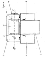
- a stand 1 along which a carriage 2 and 6 can be moved vertically in the direction of arrows a and b. They carry a carrier 3 which is horizontally displaceable on the carriage 2, 6 in the direction of arrow c.
- a cutter head 4 is rotatably supported, which is driven in rotation by a drive A. So that the cutter head 4 can be removed from the carrier 3, a clutch K (not shown in more detail) is provided between the drive A and the cutter head 4.
- the cutter head 4 has bearing pins 10, 10, on its two end faces, of which the bearing pin 10 is rotatable in a bearing bush 5 and the bearing pin 10 ⁇ in a bearing (not shown) is stored.
- the journals 10, 10 ⁇ are frustoconical, so that they center the cutter head 4 in its installed position.
- a force acting in the direction of the arrow F is applied to the bearing bush 5, by means of which the knife head 4 is clamped in its installed position.
- the force F can be applied by resilient parts, preferably by a piston-cylinder device.
- the bearing bush 5 is axially displaced in the direction of the double arrow d.
- the bearing bush 5 is guided in the carrier 3 and can be moved so far to replace the cutter head that it can be removed from the carrier 3 transversely to the axial direction or inserted into it.
- the carrier 3 is adjusted in the direction of arrow c. If a vertical adjustment of the cutter head 4 is necessary, the carrier 3 with the carriages 2 and 6 is moved in the direction of the arrows a and b along the stand 1.
- the bearing bush 5 is provided on the other side of the carrier 3, that is to say on the drive side.
- the clutch K is located in the bearing bush 5.
- this embodiment is of the same design as the embodiment according to FIG. 1.
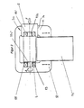
- FIG. 3 shows a machine whose stand 1a is of the same design as in the exemplary embodiment according to FIG. 1.
- the carrier 3a is guided vertically displaceably on the stand 1a in the direction of arrow a, b.
- the carrier 3a is approximately C-shaped.
- the bearing bush 5 is accommodated, in which the tool head 4 is rotatably mounted with its journal 10a.
- the bearing bush 5 In the other leg 12 of the carrier 3a there is a bearing 13 which receives the other journal 10a ⁇ of the cutter head 4.
- the bearing pins 10a, 10a 10 are cylindrical.
- the bearing bush 5 is guided axially displaceably in an opening 14 in the carrier leg 11.
- the bearing bush 5 is in turn loaded in the direction of arrow F when the cutter head 4 is to be clamped.
- the bearing bush 5 is also provided with a bearing 13 ⁇ , which receives the journal 10a.
- the bearing bush 5 can be moved axially out of the opening 14 of the carrier leg 11. Since the diameter of the opening 14 is larger than the diameter of the cutter head 4, it can be easily changed through the large opening.
- the carrier 3a with the clamped cutter head 4 can be displaced vertically in the direction of the arrows a, b along the stand 1a.
- spacer rings 15 are provided which have different thicknesses in accordance with the required changes in position. They are inserted between the bearing 13 in the carrier leg 12 and the end face of the cutter head 4 and clamped between these two parts when the cutter head 4 is installed.
- the cutter head 5b is also axially displaceable by one Axis 17 lying parallel to the axis 16 of the cutter head 4 can be pivoted.
- One end is attached to an arm 7, which in turn is firmly connected to the bearing bush 5b.
- the arm 7 is penetrated by a locking pin 9 which is axially displaceably mounted in the arm and with which the arm can be locked in its various positions on the carrier 3b.
- the carrier 3b is provided with a plug opening 20 into which the securing bolt 9 engages in the working position of the bearing bush 5b.
- the carrier 3b with the cutter head 4 and the bearing bush 5b is otherwise of the same design as in the embodiment according to FIG. 3. It can be displaced vertically along the stand 1b in the direction of the arrows a and b.
- the bearing 13 is accommodated for the one bearing journal 10b ⁇ of the cutter head 4, while the other support leg 11b has the opening 14b for the bearing bush 5b.
- the bearing bush 5b is pushed axially out of the opening 14b until it is completely free of the opening.
- the guide rod 8, which is firmly connected to the bearing bush 5b via the arm 7, is also displaced in the guide parts 18 and 19 on the carrier 3b.
- the bearing bush 5b comes out of the opening 14b, it is pivoted laterally about the axis 17 away from the region of the opening 14 (dashed lines in FIG. 4B).
- On the carrier 3b there is a holder part 21 with a in the area next to the guide parts 18 and 19 Plug-in opening into which the safety bolt 9 is inserted in the swiveled-up position to secure the bearing bush 5b.
- the cutter head 4 can be pulled out of the bearing 13 without difficulty through the opening 14b. If the cutter head 4 is to be inserted into the carrier 3b, then the bearing bush 5b is also pivoted up and locked. Through the opening 14b, the cutter head can then be conveniently inserted into the bearing 13 with its bearing pin 10b ⁇ . In this case, the corresponding spacer ring 15 is inserted between the bearing 13 and the end face of the cutter head 4 and is clamped between the bearing 13 and the cutter head when the cutter head is clamped. As soon as the cutter head 4 with its bearing pin 10b ⁇ has been pushed into the bearing 13, the securing bolt 9 is withdrawn so that it is released from the holder part 21. The arm 7 can therefore be pivoted downwards with the bearing bush 5b.
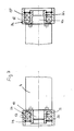
- FIGS. 5 and 6 show in detail the cutter head 4 with a further embodiment of a tool storage.
- the bearing 13 lies between an inner ring 22 and an outer ring 23.
- the two rings 22, 23 are accommodated in the carrier 3, 3a, 3b.
- the inner ring 22 has on its side facing the cutter head 4 at least two axially protruding pins 24 which engage in corresponding recesses 25 in the adjacent end face 26 of the cutter head in the installed position.
- the pins 24 are provided on an end-side, radially outwardly directed flange 27 of the inner ring 22, which is at a short distance opposite an end-side, radially inward-directed flange 28 of the outer ring 23.
- the bearing 13 is secured axially between the two rings 22, 23 by retaining rings 29 and 30. In the illustrated embodiment, two bearings 13 are arranged axially next to one another.
- the opposite bearing 13 ⁇ - in the exemplary embodiment again two axially adjacent bearings - is located between an inner ring 32 and an outer ring 31.
- the outer ring 31 has a radially inwardly directed flange 33 at the end, which has a small radial distance from an end-side, radially outwardly directed flange 34 of the inner ring 32 is opposite.
- the flange 34 of the inner ring 32 in turn has at least two axially projecting pins 35 which engage in recesses 36 in the end face 37 of the cutter head 4 in the installed position.
- the bearings 13 ⁇ are in turn axially secured by retaining rings 38 and 39 between the two rings 31 and 32.
- the outer ring 31 bears against the inner wall of the bearing bush 5.
- the bearing 13 ⁇ with the two rings 31, 32 is axially displaced with the handle 41 against the force of the compression spring 42.
- the bearing bush 5 is also axially displaced.
- the maximum displacement of the bearing and bearing bush corresponds to twice the length of the journal 10 or 10 ⁇ . This ensures that the bearing pin 10 completely emerges from the bearing bush 5 and from the bearing 13, so that the cutter head 4 can be removed from the carrier 3 without difficulty.
- the bearing pins 10, 10 ⁇ are designed as so-called hydraulic bushes. They are characterized in that they have a thin wall section 44 on the circumference, under which a pressure medium space 45 is located. Radially extending feed bores 46 open into it and connect to an axially extending central bore 47. It passes through the cutter head 4 and extends to the opposite journal 10 ⁇ , which is designed in the same way as the journal 10. When the tool body 4 is inserted into the bearings 13, 13 ⁇ , pressure medium is introduced into the spaces 45 through the bores 47, 46, as a result of which the wall sections 44 are pressed firmly against the inner wall of the inner rings 22, 31, so that the cutter head 4 is clamped properly is.
- the feed lines 46, 47 are connected to a pressure medium source.
- the cutter head 4 can be installed and removed with a robot, for example.
- the slot 40 is so long that the bearing 13 ⁇ can be moved by twice the length of the journal 10, 10 ⁇ . The cutter head 4 can then be replaced without difficulty.
- the bearing 13 ⁇ is not mounted in a bearing bush, but directly in the carrier 3, 3a, 3b. Even then, the bearing can be easily moved to replace the cutter head 4.
- FIG. 7 shows two possibilities for the formation of the bearing journals of the cutter head 4.
- the cutter head can have the cylindrical bearing journals, as is shown in the left half in FIG. 7.
- This journal 10 is housed in the bearings 13, which in turn are axially secured by the locking rings 29, 30 in the rings 22 and 23.
- the outer ring 23 is longer than the inner ring 22, as is also the case for the outer ring 31 of the embodiment according to FIGS. 5 and 6.
- the outer ring 23 is axially displaceably accommodated in the bearing bush (not shown), so that the bearing can be pushed off by cylindrical bearing journals 10 of the cutter head 4.
- the bearing journal 10c shown on the right side of FIG. 7 is frustoconical.
- the inner ring 32c has an inner lying on the surface of an imaginary cone surface 48 on which the bearing pin 10c rests in the installed position.
- the cone angle of the journal 10c is smaller than the angle of self-locking, so that the cutter head 4 can be pulled out of the bearing 13 ⁇ without difficulty.
- the outer ring 31c and the inner ring 32c are of the same design as in the embodiment according to FIGS. 5 and 6.
- the (not shown) bearing bush of the respective bearing is subjected to force (see, for example, FIG. 3), so that the cutter head 4 with its bearing journal 10, 10c is pressed into the inner ring 22, 32c and clamped .
- the cutter head 4 Since in the described embodiments the cutter head 4 is not mounted on a spindle, but is mounted directly in the corresponding bearings via the end journals, the dynamic stability obtained thereby enables the cutter head to be operated at a very high speed, this speed being up to approximately Can be 12,000 rpm. can. This enables very high feed speeds of the workpieces to be machined with the cutter head to be achieved. Since the cutter head 4 does not require an axial bore - because it is not pushed onto a spindle - the diameter of the cutter head can be small, so that the machine equipped with such a cutter head can be made compact.
- the cutter heads 4 can be replaced quickly and easily.
- the sliding Bearing bushing 5, 5b is clamped in the installed position of the cutter head by suitable, known means. If the trunnion 10c is frustoconical, the cutter head 4 must be axially preloaded, for which springs, hydraulic or pneumatic piston-cylinder arrangements, eccentrics or the like can be provided, which exert the corresponding axial feed forces on the bearing bush. If, however, the bearing journals 10, 10 ⁇ are designed as solid cylinder journals (FIGS.
Landscapes
- Engineering & Computer Science (AREA)
- Mechanical Engineering (AREA)
- Details Of Cutting Devices (AREA)
- Milling, Drilling, And Turning Of Wood (AREA)
Applications Claiming Priority (2)
| Application Number | Priority Date | Filing Date | Title |
|---|---|---|---|
| DE19863617004 DE3617004A1 (de) | 1986-05-21 | 1986-05-21 | Maschine, vorzugsweise kehlmaschine |
| DE3617004 | 1986-05-21 |
Publications (2)
| Publication Number | Publication Date |
|---|---|
| EP0246437A2 true EP0246437A2 (fr) | 1987-11-25 |
| EP0246437A3 EP0246437A3 (fr) | 1989-12-06 |
Family
ID=6301254
Family Applications (1)
| Application Number | Title | Priority Date | Filing Date |
|---|---|---|---|
| EP87105023A Withdrawn EP0246437A3 (fr) | 1986-05-21 | 1987-04-04 | Machine, par exemple raboteuse de plaques |
Country Status (2)
| Country | Link |
|---|---|
| EP (1) | EP0246437A3 (fr) |
| DE (1) | DE3617004A1 (fr) |
Cited By (4)
| Publication number | Priority date | Publication date | Assignee | Title |
|---|---|---|---|---|
| DE102007018713A1 (de) * | 2007-04-16 | 2008-10-23 | Michael Weinig Ag | Kehlmaschine sowie Hebevorrichtung für Werkzeuge zur Verwendung mit einer Kehlmaschine |
| US7919038B2 (en) | 2007-02-22 | 2011-04-05 | The Procter & Gamble Company | Method of surface treating particulate material using electromagnetic radiation |
| DE102021004822A1 (de) | 2021-09-26 | 2023-03-30 | B. Maier Zerkleinerungstechnik Gmbh | Verfahren und Vorrichtung zur Rüstung eines Messerrings eines Messerringzerspaners |
| DE102021004825A1 (de) | 2021-09-26 | 2023-03-30 | B. Maier Zerkleinerungstechnik Gmbh | Vorrichtung und Verfahren zur Wartung eines Messerrings eines Messerringzerspaners |
Family Cites Families (7)
| Publication number | Priority date | Publication date | Assignee | Title |
|---|---|---|---|---|
| US1407520A (en) * | 1922-02-21 | Assictog to anton | ||
| US1406843A (en) * | 1920-08-06 | 1922-02-14 | Anton Vonnegut | Cutter-head spindle for planers and molders |
| US1426492A (en) * | 1922-03-17 | 1922-08-22 | Anton Vonnegut | Removable cutter head for motor-driven molders |
| GB200889A (en) * | 1922-04-18 | 1923-07-18 | Thomas White & Sons Ltd | Improvements in wood working machine tools |
| GB281898A (en) * | 1927-02-02 | 1927-12-15 | John Pickles & Son Engineers L | An improvement in or relating to the mounting of cutter blocks in woodworking machines |
| US2873776A (en) * | 1951-10-08 | 1959-02-17 | Rockwell Mfg Co | Planer and attachments therefor |
| DE3318745C2 (de) * | 1983-05-24 | 1986-12-04 | Eugen Lutz GmbH u. Co Maschinenfabrik, 7130 Mühlacker | Hobelmaschine, insbesondere Handhobel |
-
1986
- 1986-05-21 DE DE19863617004 patent/DE3617004A1/de not_active Withdrawn
-
1987
- 1987-04-04 EP EP87105023A patent/EP0246437A3/fr not_active Withdrawn
Cited By (4)
| Publication number | Priority date | Publication date | Assignee | Title |
|---|---|---|---|---|
| US7919038B2 (en) | 2007-02-22 | 2011-04-05 | The Procter & Gamble Company | Method of surface treating particulate material using electromagnetic radiation |
| DE102007018713A1 (de) * | 2007-04-16 | 2008-10-23 | Michael Weinig Ag | Kehlmaschine sowie Hebevorrichtung für Werkzeuge zur Verwendung mit einer Kehlmaschine |
| DE102021004822A1 (de) | 2021-09-26 | 2023-03-30 | B. Maier Zerkleinerungstechnik Gmbh | Verfahren und Vorrichtung zur Rüstung eines Messerrings eines Messerringzerspaners |
| DE102021004825A1 (de) | 2021-09-26 | 2023-03-30 | B. Maier Zerkleinerungstechnik Gmbh | Vorrichtung und Verfahren zur Wartung eines Messerrings eines Messerringzerspaners |
Also Published As
| Publication number | Publication date |
|---|---|
| DE3617004A1 (de) | 1987-11-26 |
| EP0246437A3 (fr) | 1989-12-06 |
Similar Documents
| Publication | Publication Date | Title |
|---|---|---|
| DE19830903A1 (de) | Einrichtung sowie Verfahren zur Bearbeitung von Bohrungen in einem Werkstück unter Verwendung einer solchen Einrichtung | |
| DE4028775C1 (fr) | ||
| EP0981416B1 (fr) | Outil comportant un corps de base et procede permettant de pratiquer des alesages dans une piece a l'aide d'un tel outil | |
| DE4339754C1 (de) | Vorrichtung zum Einbringen von Bohrungen in eine Schüssel bzw. eine Felge eines Kraftfahrzeug-Rades | |
| DE2341663A1 (de) | Rotierendes werkzeug fuer holzbearbeitungsmaschinen, insbesondere spanwerkzeug wie messerkopf oder fraeser, mit einer zentralen aufnahmebohrung fuer eine antriebswelle der bearbeitungsmaschine | |
| DE2338207A1 (de) | Mehrspindelautomat, insbesondere mehrspindeldrehautomat | |
| DE1577366B1 (de) | Rundschleifmaschine zur gleichzeitigen Bearbeitung von zwei rotierenden Werkstuecken mit einem rotierenden Werkzeug | |
| DE3131107A1 (de) | "vorrichtung zur einstellung der drehachse eines gelenks zur schwenkfaehigen aufhaengung eines fuehrungslenkers eines rades am aufbau eines kraftfahrzeuges" | |
| DE2559145C3 (de) | Entgratwerkzeug | |
| DE3316283C2 (de) | Tiefbohrmaschine | |
| DE20212313U1 (de) | Vielschneidiges Rotationswerkzeug | |
| DE3605913A1 (de) | Zum nutenfraesen verstellbarer werkzeughalter an werkzeugmaschinen | |
| EP0246437A2 (fr) | Machine, par exemple raboteuse de plaques | |
| DE1143689B (de) | Fuehrungs- und Klemmvorrichtung fuer Traghuelsen im Spindelkasten von Fraes- und/oder Bohrwerken | |
| DE2105667A1 (de) | Werkzeugmaschine | |
| DE2341396B2 (de) | Einstichfräsmaschine | |
| DE1086661B (de) | Innengewinderollkopf | |
| EP0185170A2 (fr) | Mandrin à mors pour machines à tourner pour l'usinage de pièces suivant des axes multiples | |
| DE1477040A1 (de) | Werkzeughalter fuer Walzwerkzeuge | |
| DE1577366C (de) | Rundschleifmaschine zur gleichzeiti gen Bearbeitung von zwei rotierenden Werk stucken mit einem rotierenden Werkzeug | |
| DE2004715A1 (de) | Drehbare Einspannvorrichtung | |
| DE3608141C2 (fr) | ||
| DE2022226A1 (de) | Vorrichtung zum Herstellen von Nuten in Bohrungen | |
| DE29500846U1 (de) | Vorrichtung zur drehbaren Abstützung von Werkstoffstangen an Drehautomaten | |
| DE2503284A1 (de) | Walzendrehbank |
Legal Events
| Date | Code | Title | Description |
|---|---|---|---|
| PUAI | Public reference made under article 153(3) epc to a published international application that has entered the european phase |
Free format text: ORIGINAL CODE: 0009012 |
|
| AK | Designated contracting states |
Kind code of ref document: A2 Designated state(s): AT BE CH DE ES FR GB GR IT LI LU NL SE |
|
| PUAL | Search report despatched |
Free format text: ORIGINAL CODE: 0009013 |
|
| AK | Designated contracting states |
Kind code of ref document: A3 Designated state(s): AT BE CH DE ES FR GB GR IT LI LU NL SE |
|
| RHK1 | Main classification (correction) |
Ipc: B23Q 1/08 |
|
| RAP1 | Party data changed (applicant data changed or rights of an application transferred) |
Owner name: MICHAEL WEINIG AKTIENGESELLSCHAFT |
|
| STAA | Information on the status of an ep patent application or granted ep patent |
Free format text: STATUS: THE APPLICATION IS DEEMED TO BE WITHDRAWN |
|
| 18D | Application deemed to be withdrawn |
Effective date: 19900607 |
|
| RIN1 | Information on inventor provided before grant (corrected) |
Inventor name: KROECHER, HARRO Inventor name: HEIERMANN, KLAUS |