EP0246456A2 - Dispositif d'alimentation pour machines à fixer des éléments de fermeture - Google Patents
Dispositif d'alimentation pour machines à fixer des éléments de fermeture Download PDFInfo
- Publication number
- EP0246456A2 EP0246456A2 EP87105780A EP87105780A EP0246456A2 EP 0246456 A2 EP0246456 A2 EP 0246456A2 EP 87105780 A EP87105780 A EP 87105780A EP 87105780 A EP87105780 A EP 87105780A EP 0246456 A2 EP0246456 A2 EP 0246456A2
- Authority
- EP
- European Patent Office
- Prior art keywords
- conveyor belt
- belts
- textile
- piecing
- piece
- Prior art date
- Legal status (The legal status is an assumption and is not a legal conclusion. Google has not performed a legal analysis and makes no representation as to the accuracy of the status listed.)
- Withdrawn
Links
- 239000004753 textile Substances 0.000 claims abstract description 56
- 230000004888 barrier function Effects 0.000 claims description 4
- 238000000034 method Methods 0.000 abstract description 8
- 230000008569 process Effects 0.000 abstract description 7
- 230000032258 transport Effects 0.000 description 9
- 230000008901 benefit Effects 0.000 description 6
- 239000010985 leather Substances 0.000 description 5
- 230000001133 acceleration Effects 0.000 description 1
- 238000006073 displacement reaction Methods 0.000 description 1
- 230000000694 effects Effects 0.000 description 1
- 230000000284 resting effect Effects 0.000 description 1
- 230000011664 signaling Effects 0.000 description 1
- 230000007704 transition Effects 0.000 description 1
- 230000001960 triggered effect Effects 0.000 description 1
Images

Classifications
-
- A—HUMAN NECESSITIES
- A41—WEARING APPAREL
- A41H—APPLIANCES OR METHODS FOR MAKING CLOTHES, e.g. FOR DRESS-MAKING OR FOR TAILORING, NOT OTHERWISE PROVIDED FOR
- A41H37/00—Machines, appliances or methods for setting fastener-elements on garments
-
- A—HUMAN NECESSITIES
- A41—WEARING APPAREL
- A41H—APPLIANCES OR METHODS FOR MAKING CLOTHES, e.g. FOR DRESS-MAKING OR FOR TAILORING, NOT OTHERWISE PROVIDED FOR
- A41H43/00—Other methods, machines or appliances
- A41H43/02—Handling garment parts or blanks, e.g. feeding, piling, separating or reversing
- A41H43/0235—Feeding or advancing
- A41H43/0242—Conveyors therefor
Definitions
- the invention relates to a device for feeding textile pieces or the like to a piecing machine for push buttons, rivets or the like with a positioning device for the textile pieces which can be controlled by a piecing program.
- Textiles, leather goods or similar products are often provided with snaps, rivets or the like.
- Special attaching machines which carry out the attaching process fully automatically, are used to attach the push buttons or rivets.
- the snap fasteners or rivets are placed in a row at predetermined intervals.
- the textiles or leather goods are fed to the attachment point of the attachment machine for attaching the respective push button or rivet by means of special feed devices.
- a known feed device for textiles, leather goods or the like consists of a positioning device in the form of a coordinate table, on which the piece to be provided with a push button or rivet is placed by hand.
- the control of the coordinate table, ie its shift to the respective one Attaching pli.e of the attaching machine is carried out by means of an attaching program which moves the coordinate table accordingly.
- the K can be operated only intermittently oordinatentisch.
- the respective textile piece or the like must be positioned on the coordinate table.
- the positioning table then moves to the individual attachment points, where a push button or rivet is to be attached using the attachment machine.
- This procedure is particularly cumbersome when ribbons or button strips on shirts or coats are to be provided with snap fasteners or rivets which are spaced apart in a row.
- the tape or button strip must be placed on the coordinate table by hand each time, so that it is virtually out of operation during this time, since no further work can be done while the textile piece is being applied.
- the attaching machine thus experiences a downtime while it is being fitted with a new piece of textile or the like.
- a device for attaching push buttons to a piece of clothing or the like is known.
- the garment to be fitted with snaps is placed on a table of a piecing machine.
- a carriage that can be moved on a rail by means of a chain drive is provided, which has a gripper at its front end, which grips the front end of the garment and this on the movement of the carriage along the rail the attaching machine goes by.
- the carriage is driven by an electric motor by means of a clutch-brake combination, the control being effected by switching cams which are arranged along the rail and are actuated by the carriage. The positions of these switch cams determine the positions of the push buttons on the garment.
- This known attachment device has the disadvantage that the attachment positions are limited by the length of the rail, along which the slide with its gripper can be moved, and by the number of switching points by the switching cams. The maximum length of the garment to be processed is therefore limited by the length of the rail.
- it is particularly disadvantageous that at the end of a complete run and after processing a certain item of clothing, the slide with its gripper must be moved back to the starting position so that the processing of a new item of clothing can take place. The transition from one, straight, processed piece of clothing to a new one can thus only take place discontinuously in the known attachment device, which can be associated with not inconsiderable downtimes.
- the object of the invention is to further develop the known feed device in such a way that a continuous attachment of the push buttons or the like to the textile pieces or the like is possible without the work process having to be interrupted when a new textile piece is put on.
- the positioning device consists of a lower and an upper, endlessly revolving conveyor belt, that the two conveyor belts lie against each other at the same speed in the opposite sense, and that a piece of textile is clamped to transport it and that the attaching machine passes through it Transport path of the textile piece is arranged in front of the attachment point of the attachment machine, a signal transmitter for triggering the attachment program.
- the feed device designed in this way has the advantage that the piecing machine can work without interruption, without any downtimes during the feeding of a new text. til stainedes or a new leather goods occur.
- the piece of textile to be provided with a push button or with a rivet is fed to the two conveyor belts and gripped by the latter, the textile piece being clamped between the upper and lower conveyor belts.
- the textile piece is transported continuously until its front edge activates the signal transmitter and triggers the attachment program.
- the piece of textile is then positioned where a push button or rivet is to be attached.
- the positioning device proves to be particularly advantageous for tapes or button strips on shirts or coats if these pieces are transported lengthways and push buttons or rivets are attached at pre-programmed intervals and steps.
- the attachment program is processed step by step, from attachment point to attachment point. After the program has been processed, the conveyor belt system continues to run until the next piece of textile introduced activates the signal transmitter again and triggers the application program again. It is of great advantage that the next textile piece can already be fed to the piecing machine during the piecing process for a certain piece of textile, without having to interrupt its activity.
- the conveyor belts are advantageously each configured as pairs of conveyor belts. This has the advantage that the conveyor belts can be made narrow and that the goods to be loaded can still be transported properly.
- the attachment point of the attaching machine can be provided between the conveyor belts of the conveyor belt pairs, so that in this area the textile piece to be loaded is properly tightened between the conveyor belts, so that a perfect attachment process is possible.
- the conveyor belts are toothed belts. These have the advantage that they can be driven properly and without the risk of slipping.
- the transport length of the upper conveyor belt is shorter than the transport length of the lower conveyor belt, the free, protruding area of the lower conveyor belt being provided as a support area for the textile piece at the beginning of the transport route.
- trailing belts are provided that are endless and at the same speed as the conveyor belts and serve as a support surface for the textile goods. This makes it possible to place the textile piece to be processed on the free lower conveyor belt and also on the drag belts.
- the lower conveyor belt continuously transports the textile piece until it reaches the clamping area formed by the lower and upper conveyor belts, these two conveyor belts grasping the textile goods and clamping them between them.
- the additional drag belts are advantageous if large pieces of textile are to be fed to the attaching machine so that the entire piece of textile lies flat.
- the drag straps are preferably flat belts.
- an adjustable stop is arranged to the side of the conveyor belts, which aligns the drawn-in textile piece during the pulling-in and thus the textile piece is directed towards the attachment point of the attachment machine.
- a tensioning device is preferably provided for the conveyor belt and the drag belts.
- Another feature of the invention proposes that the upper conveyor belt is pressed onto the lower conveyor belt by means of spring-loaded rollers.
- pieces of textile of different thicknesses can also be transported correctly, with the piece of textile to be transported additionally being clamped properly between the upper and lower conveyor belts. This prevents unintentional moving of the textile piece.
- a common drive is preferably provided for the conveyor belts.
- the common drive has the advantage that a constant rotational speed of the two conveyor belts is guaranteed at all times.
- the invention proposes that the signal transmitter is a light barrier. Instead of the light barrier, mechanical switches or the like can also be provided.
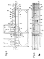
- the first embodiment shown in FIGS. 1 and 2 consists of a box-like frame 1, between the side walls 2 rollers 3 are freely rotatable.
- An endless lower conveyor belt 4 is guided around the rollers 3 in the manner shown in FIG. 1, which lies on top of a plate 5 of the frame 1 and is therefore flat at all times and cannot sag.
- the top view in FIG. 2 shows; that the lower conveyor belt 4 consists of a pair of conveyor belts, the individual conveyor belts being narrow. Otherwise, the lower conveyor belts 4 are designed as toothed belts.
- a total of three drag belts 6 are guided in a corresponding manner parallel to the lower conveyor belt 4, these drag belts 6 being designed as flat belts.
- the width of the drag straps 6 is selected such that they form a support surface.
- the lower conveyor belt 4 and the drag belts 6 are driven via the roller 3 shown on the far left in the drawing, which is designed as a drive shaft 7 and is rotated by a drive, not shown. As indicated by the arrow, the direction of rotation of the lower conveyor belt 4 and the three drag belts is counterclockwise.
- a tensioning device 8 is provided, in which the belts 4, 6 are guided over a laterally offset roller 3, which is displaceable.
- an assembly machine 9 is arranged extil unitede the push buttons, rivets or the like. At T, leather products or the like. Attaches in a known manner.
- the attachment point 10 of the attachment machine 9 lies between the two individual belts of the lower conveyor belt pair 4.
- an upper conveyor belt 12 is guided on the frame 1 around rollers 11, this upper conveyor belt 12 also being endless and consisting of toothed belts.
- the upper conveyor belt 12 is designed as a pair of conveyor belts with narrow individual conveyor belts.
- the rollers 11 ' are arranged at the ends of schematically indicated levers 13, these levers 13 being pivotable about articulation points 14, each with a spring 15, the levers 13 together with the rollers 11' and thus the upper conveyor belt 12 for contact presses down on the lower conveyor belt 4.
- the levers 13 and the springs 15 are articulated on a bar 16 arranged on the frame 1.
- the upper conveyor belt 12 is driven via a drive shaft 17 which has the same diameter as the drive shaft 7 of the lower conveyor belt 4. Since the drive for these two drive shafts 7, 17 is the same, they have the same rotational speed, but with the drive shaft 17 for the upper conveyor belt 12 rotates clockwise and thus the upper conveyor belt 12 rotates clockwise. Due to the same rotational speeds of the lower and the upper conveyor belt 4, 12, these have the same speed in the area of the plate 5 of the frame 1, where the two belts 4, 12 lie against one another.
- a signal transmitter 18 which can be a light barrier or a mechanical switch, is arranged in front of the attaching machine 9. This signal transmitter 18 lies in the transport path of a piece of textile or the like to be transported by the two conveyor belts 4, 12.
- an adjustable stop 19 is arranged laterally to the lower conveyor belt 4.
- the lower conveyor belt 4 and the upper conveyor belt 12 form a conveyor belt system which consists of a support area 20 and a clamping area 21.
- the support area 20 is formed solely by the lower conveyor belt 4 and the three drag belts 6, while the clamping area 21 is additionally formed by the upper conveyor belt 12.
- the piece of textile or the like to be provided with a push button or with a rivet is placed on the free lower conveyor belt 4 in the support area 20 and aligned against the adjustable stop 19 during the drawing in.
- the drag straps 6 serve as a support surface for large textile pieces.
- the conveyor belt system runs continuously during this workflow.
- the textile piece is gripped by the upper conveyor belt 12 and clamped between the latter and the lower conveyor belt 4. In this state, the textile piece is fed to the piecing machine 9.
- the signal transmitter 18 is located in front of the attachment point 10 of this attachment machine 9.
- the front edge of the piece of textile to be fitted actuates the signal transmitter 18 and triggers the attachment program for attaching the push buttons, rivets or the like.
- the conveyor belt system 4, 12 is first stopped. At pre-programmed intervals and steps, push buttons, rivets or the like are attached to the respective attachment point.
- a tachometer generator and an incremental displacement sensor are integrated in the drive, so that an exact positioning of the textile piece with appropriate acceleration and braking ramps is possible.
- the conveyor belt system 4, 12 After the program has been processed with the appropriate distance to the first attachment point, the distances between the attachment points and the number of attachment points, the conveyor belt system 4, 12 returns to the continuous run, so that the textile piece which has now been fitted can be removed.
- a new textile piece can already be placed in the support area 20 of the lower conveyor belt 4, so that the piecing machine 9 can also populate this further textile piece with push buttons, rivets or the like without interruption.
- the piecing program is triggered again by actuating the signal transmitter 18 when the previous textile piece is being fitted, the whole process being repeated. This can go on forever.
- the feed device designed in this way is particularly suitable when pushbuttons, rivets or the like are to be attached to tapes or button strips on shirts or coats, ie when the attachment points lie in a row. Instead Individual attachments are of course also possible if, for example, a push button is to be attached to a pocket.
- Attaching machines can also be integrated into the conveyor belt system, which can optionally attach two article type combinations, for example with a push-button ball-toothed ring / eyelet-toothed ring.
Landscapes
- Engineering & Computer Science (AREA)
- Textile Engineering (AREA)
- Treatment Of Fiber Materials (AREA)
- Advancing Webs (AREA)
Applications Claiming Priority (2)
| Application Number | Priority Date | Filing Date | Title |
|---|---|---|---|
| DE19863616902 DE3616902C1 (de) | 1986-05-20 | 1986-05-20 | Zufuehrvorrichtung bei Ansetzmaschinen |
| DE3616902 | 1986-05-20 |
Publications (2)
| Publication Number | Publication Date |
|---|---|
| EP0246456A2 true EP0246456A2 (fr) | 1987-11-25 |
| EP0246456A3 EP0246456A3 (fr) | 1989-11-02 |
Family
ID=6301193
Family Applications (1)
| Application Number | Title | Priority Date | Filing Date |
|---|---|---|---|
| EP87105780A Withdrawn EP0246456A3 (fr) | 1986-05-20 | 1987-04-18 | Dispositif d'alimentation pour machines à fixer des éléments de fermeture |
Country Status (2)
| Country | Link |
|---|---|
| EP (1) | EP0246456A3 (fr) |
| DE (1) | DE3616902C1 (fr) |
Cited By (2)
| Publication number | Priority date | Publication date | Assignee | Title |
|---|---|---|---|---|
| US6105230A (en) * | 1999-02-27 | 2000-08-22 | Bracco Research Usa | Method and apparatus for syringe barrel closure removal and measurement of breakaway and running forces of a plunger in a syringe barrel |
| RU2178472C1 (ru) * | 1997-11-24 | 2002-01-20 | Мьянг Вон САХ | Устройство для подачи пуговиц, имеющее функцию контроля ширины и центрирования |
Families Citing this family (1)
| Publication number | Priority date | Publication date | Assignee | Title |
|---|---|---|---|---|
| TR201709257A2 (tr) * | 2017-06-21 | 2019-01-21 | Silverline Enduestri Ve Ticaret Anonim Sirketi | Kutu çakma maki̇nesi̇ |
Family Cites Families (3)
| Publication number | Priority date | Publication date | Assignee | Title |
|---|---|---|---|---|
| US3263887A (en) * | 1965-02-17 | 1966-08-02 | Scovill Manufacturing Co | Automatic fastener setting machine |
| US3602418A (en) * | 1970-04-27 | 1971-08-31 | Trw Inc | Fastener-attaching machine having an automatic work-transporting mechanism |
| DE2533020B2 (de) * | 1975-07-24 | 1977-07-21 | Stocko Metallwarenfabriken Henkels Und Sohn, 5600 Wuppertal | Vorrichtung zum anbringen von befestigungselementen, insbesondere druckknopfteilen |
-
1986
- 1986-05-20 DE DE19863616902 patent/DE3616902C1/de not_active Expired
-
1987
- 1987-04-18 EP EP87105780A patent/EP0246456A3/fr not_active Withdrawn
Cited By (2)
| Publication number | Priority date | Publication date | Assignee | Title |
|---|---|---|---|---|
| RU2178472C1 (ru) * | 1997-11-24 | 2002-01-20 | Мьянг Вон САХ | Устройство для подачи пуговиц, имеющее функцию контроля ширины и центрирования |
| US6105230A (en) * | 1999-02-27 | 2000-08-22 | Bracco Research Usa | Method and apparatus for syringe barrel closure removal and measurement of breakaway and running forces of a plunger in a syringe barrel |
Also Published As
| Publication number | Publication date |
|---|---|
| DE3616902C1 (de) | 1987-08-27 |
| EP0246456A3 (fr) | 1989-11-02 |
Similar Documents
| Publication | Publication Date | Title |
|---|---|---|
| DE3022525C2 (de) | Verfahren und Vorrichtung zum Aufbringen eines Aufklebers auf eine Endlosbahn | |
| DE4107224C1 (fr) | ||
| DE1460125C3 (de) | Vorrichtung zum Schneiden von Textilien | |
| DE69422661T2 (de) | Verfahren und Vorrichtung zum Einwickeln von Gegenständen | |
| DE2432797C2 (de) | Vorrichtung zum Überführen eines Eingangsstromes aus aneinander anliegenden Gegenständen in einen Ausgangsstrom aus unter Abstand aufeinander folgenden Gegenständen | |
| EP1097265B1 (fr) | Dispositif et procede pour transporter un article plat | |
| DE1813817B2 (de) | Vorrichtung zum Trennen und Weiterfördern von in einer ununterbrochenen Reihe zulaufenden flachen Gegenständen | |
| EP0101025A2 (fr) | Dispositif de retournement dans une ligne de transport entre deux machines d'usinage | |
| DE10000262C2 (de) | Vorrichtung zum Transport eines flächigen Warenstückes | |
| DE1431009A1 (de) | Vorrichtung zum intermittierenden Transport und Ablaengen endloser Teigplatten zur Herstellung von Back- oder Suesswaren | |
| EP0246456A2 (fr) | Dispositif d'alimentation pour machines à fixer des éléments de fermeture | |
| EP1318958A1 (fr) | Procede et dispositif d'apport d'objets reguliers a une station de travail | |
| DE2656956C3 (de) | Vorrichtung zum Absetzen von Spaltplatten auf Paletten | |
| DE1233244B (de) | Vorrichtung zum rotierenden Bearbeiten kontinuierlich oder intermittierend gefoerderter Bahnen | |
| DE2824084C2 (de) | Eingabevorrichtung für Mangeln o.dgl. | |
| DE1937082B2 (de) | Verfahren und vorrichtung zum untereinander-staffeln von briefumschlaegen, beuteln oder aehnlichen werkstuecken | |
| DE3022505C2 (fr) | ||
| CH631410A5 (en) | Device for homogenising an imbricated stream formed from flat products, in particular printed products | |
| DE2227135C3 (de) | Vorrichtung zum gruppenweisen Abtrennen einer vorbestimmten Anzahl von sich schuppenartig Überlappenden, flachen Gegenständen | |
| EP0054890A1 (fr) | Transporteur pour pièces à usiner, en particulier pour des petites pièces | |
| DE2801686B1 (de) | Vorrichtung zum Fördern und Abgeben von Reißverschlüssen an eine Verpackung o.dgl | |
| CH459145A (de) | Sammeldrahtheftmaschine | |
| DD235682A5 (de) | Absetzeinrichtung fuer liegende flacherzeugnisse oder waesche | |
| DE1802493B1 (de) | Zufuehrvorrichtung fuer Waeschestuecke zu einer Buegelmaschine,insbesondere Mangel | |
| DE7541002U (de) | Vorrichtung zur behandlung von auf einer transporteinrichtung transportierten gegenstaenden, insbesondere zur kennzeichnung von diarahmen |
Legal Events
| Date | Code | Title | Description |
|---|---|---|---|
| PUAI | Public reference made under article 153(3) epc to a published international application that has entered the european phase |
Free format text: ORIGINAL CODE: 0009012 |
|
| AK | Designated contracting states |
Kind code of ref document: A2 Designated state(s): AT DE FR NL SE |
|
| PUAL | Search report despatched |
Free format text: ORIGINAL CODE: 0009013 |
|
| AK | Designated contracting states |
Kind code of ref document: A3 Designated state(s): AT DE FR NL SE |
|
| 17P | Request for examination filed |
Effective date: 19891106 |
|
| 17Q | First examination report despatched |
Effective date: 19910327 |
|
| STAA | Information on the status of an ep patent application or granted ep patent |
Free format text: STATUS: THE APPLICATION HAS BEEN WITHDRAWN |
|
| 18W | Application withdrawn |
Withdrawal date: 19910608 |
|
| R18W | Application withdrawn (corrected) |
Effective date: 19910608 |
|
| RIN1 | Information on inventor provided before grant (corrected) |
Inventor name: KUEBELSTEIN, LUTZ |