EP0246474A2 - Meuble d'assise, notamment une chaise - Google Patents
Meuble d'assise, notamment une chaise Download PDFInfo
- Publication number
- EP0246474A2 EP0246474A2 EP87106335A EP87106335A EP0246474A2 EP 0246474 A2 EP0246474 A2 EP 0246474A2 EP 87106335 A EP87106335 A EP 87106335A EP 87106335 A EP87106335 A EP 87106335A EP 0246474 A2 EP0246474 A2 EP 0246474A2
- Authority
- EP
- European Patent Office
- Prior art keywords
- stiffening member
- section
- seating furniture
- seating
- approximately
- Prior art date
- Legal status (The legal status is an assumption and is not a legal conclusion. Google has not performed a legal analysis and makes no representation as to the accuracy of the status listed.)
- Ceased
Links
Images



Classifications
-
- A—HUMAN NECESSITIES
- A47—FURNITURE; DOMESTIC ARTICLES OR APPLIANCES; COFFEE MILLS; SPICE MILLS; SUCTION CLEANERS IN GENERAL
- A47C—CHAIRS; SOFAS; BEDS
- A47C3/00—Chairs characterised by structural features; Chairs or stools with rotatable or vertically-adjustable seats
- A47C3/02—Rocking chairs
- A47C3/021—Rocking chairs having elastic frames
Definitions
- the invention relates to a piece of seating furniture, in particular a chair, with at least one profiled support which stands at the side of a seat part and forms differently directed support sections in side view and which has an intermediate section which deviates from the vertical position and which adjoins the end sections in an articulated, resilient manner, resiliently from the vertical position .
- Seating furniture of this type which can also be a stool, armchair, two-seater or multi-seater, is usually referred to as a so-called cantilever chair, in which the seat part is vertically resilient under load due to the resilient seating base frame, which is generally formed by two side profile supports conditions, usually on a relatively large circular arc section.
- the profile beams which are mostly metallic tube profiles, need to be dimensioned very strongly in order to prevent material fatigue breaks and to cause a relatively steeply increasing spring characteristic. Nevertheless, seating of this type tends to have a rocking or rocking effect, which is particularly undesirable when used in row seating.
- the invention is based on the object of designing seating of the type mentioned in such a way that on the one hand the advantages of the seating furniture designed as cantilever chairs are given and on the other hand an excessive vibration effect can nevertheless be avoided.
- This object is achieved in a piece of seating furniture of the type described at the outset according to the invention in that the two end sections of the profile beam are connected to one another via an elongated stiffening member which, in side view, has a position deviating from the congruent position with the intermediate section.
- the profile carrier is thus connected inside or outside at least one end of the stiffening member at a small or greater distance from this end to a stiffening member which can extend approximately over the entire height of the profile carrier and at least the intermediate section with regard to its resilient pivoting movement depending on the position of the stiffening member and arrangement more or less captivating from its connecting points, so that the spring characteristic of the profile beam can be influenced almost arbitrarily.
- stiffening member crosses the intermediate section or its central axis, in particular in an X-shape, approximately at the height of the seat part, in a side view of the seating furniture, so that it is most valuable that a lower part of the stiffening member with the part of the profile beam lying at the same height forms an approximately isosceles triangle in side view, for example, the tip of which is expedient approximately at the level of the underside of the seat part, that is to say slightly below the seat surface.
- the stiffening member can be directed downwards at an angle such that it lies completely within the curved or circular arc traversed by this attachment point during the resilient movement, the angle of inclination of the stiffening member being between approximately 40 ° and 70 ° can.
- the stiffening member is expediently attached to at least one end section immediately adjacent to its free end, when it is attached to both end sections in this way , a maximum length of the stiffening member, for example made of structural steel, plastic or the like, can be achieved.
- stiffening member is rigidly attached to the upper and / or the lower end section.
- the rigid attachment can be done by screwing, riveting, gluing and, with suitable materials, by welding or the like.
- a very simple attachment is possible in that the stiffening member is fastened with an end pin which is at an angle to it, for example engaging directly in an opening in the wall of the end section, which is advantageously formed in one piece with the stiffening member, in particular by a End bend is formed.
- stiffening member secures the profiled member in a spring-loaded position under tensile load and thereby gives the chair frame a spring characteristic that begins above zero
- stiffening member by a pure, for example, slack tension member, such as a rope.
- slack tension member such as a rope
- the stiffening member can be formed by a profile bar with any cross-section, but can also have cross-sectional widenings and cross-sectional tapering over its length, preferably flowing.
- the stiffening member has circular cross sections and / or a smooth surface, so that it offers the lowest possible resistance when touched.
- stiffening member slightly in the initial position, that is to say when the seating furniture is not under load, or to make it slightly curved in a manner deviating from the straight line, so that it is only slightly curved further in this predetermined direction of curvature when subjected to pressure.
- the arrangement is in any case, so even in the initial state straight stretched training expediently such that the stiffening member is deformed in a load only in a single plane, which is suitably parallel to the plane of the profile beam or is substantially vertical.
- the upper and / or the lower end section of the in particular Z-shaped profile carrier is approximately parallel to the standing. plane of the seating furniture, so that the lower end section can be provided directly as the arm forming the standing surface of the seating furniture, while the upper end section can form an armrest.
- the upper end of the stiffening member can be provided approximately vertically above the pivot axis approximately at the level of the standing plane, which is determined by the transition of the intermediate section into the lower end section.
- the upper end section is inclined upwards, in particular obliquely backwards, so that it encloses with the intermediate section an angle opening backwards of approximately 90 ° or more.
- the upper end of the stiffening member can either be fastened in the transition area between this end section and the intermediate section on the profile carrier, or it can be substantially congruent with this end section in a side view and on this between the mentioned transition and its end facing away from the intermediate section.
- the upper end of the stiffening member is therefore advantageously above the seat part, and it can end in side view in the area of the associated side edge of the backrest, so that the upper end part of the stiffening member lying above the seat part crosses the angle between the seat part and the backrest in the manner of a side cheek and forms an additional lateral limitation for the seated person.
- the stiffening member can have very slim cross-sections in relation to the cross-sections of the rest of the chair frame, for example a diameter of about 8 mm, whereby it can be provided both with solid cross-sections and, for example in the manner of a tube, with hollow cross-sections.
- the profile carrier expediently has flat cross sections, which can be rectangular, oval or similar and whose larger cross-sectional dimension lies in the width direction of the seating furniture.
- the cross sections of the profiled beams can optionally be chosen to be weaker than in the case of seating furniture without such a stiffening member.
- a piece of seating furniture 1 has a chair frame 2 which is at least partially made of metal, in particular tubular steel and / or at least partially made of plastic, wood, in particular plywood, or the like and which carries a seat body 3.
- the seat body 3 which is expediently formed from a plate or has an essentially constant thickness and is approximately angular in side view, forms a seat part 4 with its lower leg and a backrest 5 with its rear leg, which projects upwards.
- the chair main body 2 is mainly defined by two sides of the Wegkör ers p 3 and formed directly adjacent to said stationary side parts 6 each have an approximately Z-shaped bent profile beam. 7
- Each of the two identical profiled beams 7 forms a lower, approximately horizontal or parallel to the standing surface of the seating 1 end portion 8, an equally parallel upper, but opposite rearward end portion 9 and a connecting this, from the rear end of the end portion 8 to the front inclined intermediate section 10, which in the exemplary embodiment shown merges directly into the end sections 8, 9 via part-circular bends, although it is also conceivable that between the intermediate section 10 and at least one end section there is yet another one, taking a different angular position with respect to both of these sections Section is provided.
- the two side parts 6 are connected to one another via a crossmember 11 in that this crossmember 11 is rigidly attached to the mutually facing inner sides of the profiled beams 7, namely the intermediate sections 10 by welding or the like.
- the crossmember 11 is located in the area of the rear half of the seat part 4 immediately below it, so that the seat body 3 can be supported by resting on the crossmember 11 and the seat part 4 protrudes freely from the crossmember 11 and thus possibly resiliently, wherein the seat body 3 can be formed by a molded part made of wood, plastic or the like.
- the seat body 3 can also be fixed in the area of the backrest 5 in addition to the side parts 6 or the profile beams 7, preferably approximately at half the height of the backrest 5, the backrest 5 advantageously being fastened in the area of the rear ends of the upper end sections 9 is and these rear ends in side view extend at most to the back of the backrest 5.
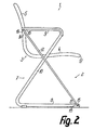
- Each side part 6 is provided with at least one rod-shaped and preferably continuously one-piece stiffening member 12 which is resilient in its longitudinal direction and which is at least approximately rectilinearly stretched when the seat 1 is unloaded and which, in side view according to FIG. 2, encloses two approximately isosceles triangles with the profiled support 7 their tips are directed towards each other and the upper one is smaller than the lower one.
- the stiffening member 12 is attached with its ends 13, 14 essentially rigidly to the associated profiled support 7, the lower end 13 in the side view according to FIG front end 15 of the lower end section 8, namely directly adjacent to its end surface and the upper end 14 in the region of the rear end 16 of the upper end section 9 is also provided directly adjacent to its end surface.
- the lower end 13 of the stiffening member 12 is thus in the side view according to FIG. 2 almost vertically below the front edge 17 of the seat part 4 or only slightly set back relative to this.
- the upper end 14 of the stiffening member 12 lies in the area of the rear of the seating furniture 1, namely in a side view according to FIG. 2, between the front and the rear of the backrest 5 approximately in half of its height.
- the stiffening member 12 crosses the intermediate section 10 at an angle deviating from 90 ° at a height which is in the region of the crossmember 11, that is to say directly below the seat part 4.
- the front end of the upper end section 9 lies in a side view according to FIG. 2 in a vertical plane which is provided approximately in the middle between the crossing point and the lower end 13 of the stiffening member 12.
- Each of the two stiffening members 12 of the same design and in side view according to FIG. 2 as well as the profiled beams 7 are congruent with one another at the lower and upper ends each have an approximately perpendicular to it, short and directed against the associated profile support 7 end pin 18 or 19, which can be formed in a simple manner by a corresponding bending of the stiffening member 12.
- a closely matched bore is provided for each end pin 18 or 19, into which the associated end pin 18 or 19 is inserted and secured, for example, by welding from the inside, so that the stiffening member 12 in Front view according to FIG. 3 lies between its end pins 18, 19 with a small constant gap distance without contact adjacent to the associated profiled support 7.
- the upper end pin 19 can be extended such that it passes through the upper end section 9 of the profile support 7, that is, protrudes beyond the inside thereof and serves to secure the position of the backrest 5, whereby it engages behind this backrest 5 or in a corresponding opening on the side edge of the backrest 5 can intervene so that additional fastening means for fastening the backrest 5 can be dispensed with.
- Each profile support 7 expediently has profile cross-sections which are at least approximately flat-rectangular or flat-oval and whose larger cross-sectional extent is in the width direction of the seating furniture 1, that is to say horizontally, the larger cross-sectional extent expediently being approximately twice as large as the smaller cross-sectional extent lying at right angles thereto.
- the mean radii of curvature of the part-circular curved transition sections between the intermediate section 10 and the end sections 8, 9 can be selected to be relatively small and between the two crosses mentioned sectional dimensions of the profile beams.
- the largest cross-sectional dimension of the stiffening member 12 can be chosen to be significantly smaller, namely, for example, only have approximately one sixth of the largest cross-sectional dimension of the profile beam 7.
- the lower end portion 8 of the profile beam 7 can be curved slightly upwards between its ends in a side view according to FIG. 2, so that it is ensured that it only stands on the floor in the region of these ends.
- 8 blocks in the form of profile blocks made of plastic or the like are arranged at the front and rear ends of each lower end section, of which the front covers the front end face of the end section 8.
- the upper end section 9 can also be provided on the upper side with a cushion-like cover that is approximately continuous over its length and expediently covers the rear end face of the upper end section 9 and extends over the curved transition area between the front end of the end section 9 and the intermediate section 10 can, so that a padded armrest is formed.
- each profile carrier 7a of the chair frame 2a takes a position which is parallel to the end section 8a or deviates from the horizontal position, in particular for ver stiffening member 12a parallel position, wherein it is inclined upwards and backwards, such that the upper end part of the stiffening member 12a in side view according to FIG. 4 is congruent with this end section 9a and extends approximately over its entire length.
- the stiffening member 12a therefore does not cross the profiled support 7a or the intermediate section 10a, but is located immediately adjacent to the end section 9a from the transition section between the end section 9a and the intermediate section 10a.
- the upper end pin 19a which could also be provided in the area of this transition section, is, as in the case of the embodiment according to FIGS. 1 to 3, above the seat part 4a in the area of the backrest 5a. Because the cross-sectional extent of the stiffening member 12a is smaller than the smaller cross-sectional extent of the profile beam 7a, the upper end part of the stiffening member 12a in side view according to FIG. 4 can lie between the planes of the front and the rear of the end section 9a, it also being conceivable that this upper end part lies within the end section 9a.
- the part of the seat part 4 lying in front of the crossmember 11 can also be resiliently supported with one or more spring tongues lying freely next to one another and supported at least with their front ends on the underside of the seat part 4.
- These spring tongues are expediently fastened to the crossmember 11, which in this case can be formed by a slotted tube into which the spring tongues with fastening heads produced by bending at their rear ends intervene that they pass through the slot through the length of the tube and adapted to its thickness secured against rotation adjacent to their mounting heads.
- the seat body 3 is expediently pivotable or oscillating about a horizontal transverse axis, for example below the seat part 4 in the region of the upper side of the cross member 11, and is secured by the spring tongues against excessive forward and / or rearward tilting movements.
- transverse axis can also coincide with the central axis of the cross member 11, which is formed, for example, by a cylindrical tube, so that it forms a rotary bearing for the seat body 3 in that it is supported by clamp-like bearing shells attached to the underside of the seat part 4 at least over part of its circumference is included.
- the respective end 13 or 14 or the respective end pin 18 or 19 can engage in a separate end piece made of plastic, steel or the like, which is attached to the free end of the associated end section 8 or 9, for example, in that it has a shaft section which can be inserted in a form-fitting manner and a head section projecting beyond the end face for the engagement of the respective end pin 18 or 19.
Landscapes
- Chairs Characterized By Structure (AREA)
- Chair Legs, Seat Parts, And Backrests (AREA)
Applications Claiming Priority (2)
| Application Number | Priority Date | Filing Date | Title |
|---|---|---|---|
| DE19863617298 DE3617298A1 (de) | 1986-05-23 | 1986-05-23 | Sitzmoebel, insbesondere stuhl |
| DE3617298 | 1986-05-23 |
Publications (2)
| Publication Number | Publication Date |
|---|---|
| EP0246474A2 true EP0246474A2 (fr) | 1987-11-25 |
| EP0246474A3 EP0246474A3 (fr) | 1988-04-06 |
Family
ID=6301428
Family Applications (1)
| Application Number | Title | Priority Date | Filing Date |
|---|---|---|---|
| EP87106335A Ceased EP0246474A3 (fr) | 1986-05-23 | 1987-05-01 | Meuble d'assise, notamment une chaise |
Country Status (5)
| Country | Link |
|---|---|
| US (1) | US4787672A (fr) |
| EP (1) | EP0246474A3 (fr) |
| AU (1) | AU7333987A (fr) |
| CA (1) | CA1275238C (fr) |
| DE (1) | DE3617298A1 (fr) |
Families Citing this family (27)
| Publication number | Priority date | Publication date | Assignee | Title |
|---|---|---|---|---|
| US5112107A (en) * | 1990-09-12 | 1992-05-12 | Brown Jordan Company | Spring-action chair |
| USD343527S (en) | 1990-10-24 | 1994-01-25 | Emilio Ambasz | Padded chair |
| USD346283S (en) | 1991-09-17 | 1994-04-26 | Tecno S.P.A. Mobili E Forniture Per Arredamento | Chair |
| DE4135488A1 (de) * | 1991-10-28 | 1993-04-29 | Leistritz Ag | Verfahren zur versteifung eines rohrprofiltraegers |
| USD423242S (en) * | 1998-11-23 | 2000-04-25 | Steve Lin | Chair |
| USD478748S1 (en) | 2002-09-23 | 2003-08-26 | Lausan Chung-Hsin Liu | Swing chair support frame |
| USD490622S1 (en) | 2003-06-13 | 2004-06-01 | Hon Technology Inc. | Armless chair |
| USD503054S1 (en) * | 2003-06-13 | 2005-03-22 | Hon Technology Inc. | Chair base |
| US7384100B2 (en) * | 2004-05-06 | 2008-06-10 | Marco C. Perry | Flexible reclining chair |
| WO2006017765A2 (fr) * | 2004-08-05 | 2006-02-16 | Wenger Corporation | Sieges fonctionnels pour musiciens |
| USD524082S1 (en) | 2005-08-05 | 2006-07-04 | Wenger Corporation | Chair frame |
| USD523255S1 (en) | 2005-08-05 | 2006-06-20 | Wenger Corporation | Posture chair |
| USD524583S1 (en) | 2005-08-05 | 2006-07-11 | Wenger Corporation | Chair, seat and back |
| GB0810985D0 (en) * | 2008-06-17 | 2008-07-23 | Higgs Tom | Dynamic flex chair support |
| WO2012020071A1 (fr) * | 2010-08-10 | 2012-02-16 | Ass Einrichtungssysteme Gmbh | Meuble d'assise |
| DE102010054887A1 (de) | 2010-12-17 | 2012-06-21 | VS Vereinigte Spezialmöbelfabriken GmbH & Co. KG | Sitzmöbel |
| AU339268S (en) * | 2011-04-12 | 2011-11-04 | B&B Italia S P A | Armchair |
| US9533766B2 (en) * | 2011-05-20 | 2017-01-03 | Zodiac Seats France | Kinematic seat with elastic pivot |
| USD683572S1 (en) * | 2012-06-07 | 2013-06-04 | American Seating Company | Chair arm |
| US9173492B1 (en) * | 2014-06-06 | 2015-11-03 | Jacques Fortin | Self-reclining chair |
| USD753405S1 (en) * | 2015-02-15 | 2016-04-12 | Conor Coghlan | Lounge chair |
| USD773220S1 (en) * | 2015-06-05 | 2016-12-06 | Target Brands, Inc. | Display unit |
| US11266244B2 (en) * | 2018-02-16 | 2022-03-08 | Barrett Studios, Inc. | Chair assembly |
| USD975463S1 (en) * | 2020-12-28 | 2023-01-17 | Sophia & William Brands Co. Ltd | Elastic chair |
| IT202100006467A1 (it) * | 2021-03-18 | 2022-09-18 | Pro Cord Spa | Sedia con sedile e schienale oscillanti |
| USD1110754S1 (en) * | 2023-02-07 | 2026-02-03 | Industrial Woodworking Corporation | Chair |
| USD1102767S1 (en) * | 2023-06-08 | 2025-11-25 | Nuu Garden Corporation | Chair |
Family Cites Families (18)
| Publication number | Priority date | Publication date | Assignee | Title |
|---|---|---|---|---|
| DE532037C (de) * | 1931-08-21 | Anton Heythum | Stuhl aus Stahlrohr | |
| NL54112C (fr) * | 1900-01-01 | |||
| DE568705C (de) * | 1933-01-23 | Anton Lorenz | Sitzmoebel mit aus fortlaufend schlingenfoermig gebogenem, federndem Werkstoff | |
| US1377600A (en) * | 1919-10-27 | 1921-05-10 | Austin H Prest | Rocking-chair |
| DE569649C (de) * | 1930-09-17 | 1933-02-06 | Hans Nitzschke | Stahlrohrstuhlgestell |
| CH170985A (de) * | 1932-11-22 | 1934-08-15 | Breuer Marcel | Gestell für federnde Sitzmöbel. |
| DE662762C (de) * | 1935-01-12 | 1938-07-21 | Andreas Gaal | Moebel mit einem Gestell aus federndem Werkstoff |
| US2006421A (en) * | 1935-03-08 | 1935-07-02 | Trainor Nat Spring Company | Spring frame seat |
| FR805612A (fr) * | 1935-08-10 | 1936-11-25 | Perfectionnements aux sièges à armature métallique tubulaire | |
| US2218863A (en) * | 1938-11-22 | 1940-10-22 | Wagner Fred | Chair construction |
| GB583994A (en) * | 1944-09-15 | 1947-01-03 | Kingfisher Ltd | Improvements relating to chairs |
| US2679282A (en) * | 1949-08-19 | 1954-05-25 | Edward W Anderegg | Infant's chair |
| US2981315A (en) * | 1956-06-15 | 1961-04-25 | Schaffer Harvey | Resilient chair |
| FR1350571A (fr) * | 1963-03-18 | 1964-01-24 | Siège mobile | |
| US3357741A (en) * | 1966-11-23 | 1967-12-12 | Vadner Samuel | Chair |
| DE7825276U1 (de) * | 1978-08-24 | 1978-11-30 | Max Meier Gmbh + Co Metallwarenfabrik, 7585 Lichtenau | Stuhl bzw. sessel, insbesondere gartenstuhl bzw. -sessel |
| US4542938A (en) * | 1983-04-11 | 1985-09-24 | Suncast Corporation | Flexible chair |
| IL73031A (en) * | 1984-09-19 | 1986-11-30 | Yaacov Kaufman | Improved self adjusting chair |
-
1986
- 1986-05-23 DE DE19863617298 patent/DE3617298A1/de not_active Withdrawn
-
1987
- 1987-05-01 EP EP87106335A patent/EP0246474A3/fr not_active Ceased
- 1987-05-12 US US07/048,760 patent/US4787672A/en not_active Expired - Fee Related
- 1987-05-13 CA CA000537044A patent/CA1275238C/fr not_active Expired - Lifetime
- 1987-05-22 AU AU73339/87A patent/AU7333987A/en not_active Abandoned
Also Published As
| Publication number | Publication date |
|---|---|
| DE3617298A1 (de) | 1987-11-26 |
| CA1275238C (fr) | 1990-10-16 |
| EP0246474A3 (fr) | 1988-04-06 |
| AU7333987A (en) | 1987-11-26 |
| US4787672A (en) | 1988-11-29 |
Similar Documents
| Publication | Publication Date | Title |
|---|---|---|
| DE3617298A1 (de) | Sitzmoebel, insbesondere stuhl | |
| DE8205761U1 (de) | Sitzmoebel | |
| DE4427754A1 (de) | Stuhl, insbesondere Drehstuhl | |
| DE3232771A1 (de) | Arbeits-sitzmoebel | |
| EP0649618A2 (fr) | Chaise | |
| EP0198056B1 (fr) | Support de siege pour chaises, surtout pour des chaises de travail | |
| DE2232117C3 (de) | Höhen- und neigungsverstellbarer Fahrzeugsitz | |
| DE1963397B2 (de) | Feder für einen Federrost | |
| DE2307771A1 (de) | Federmechanismus fuer einen kippbaren teil eines kippstuhles | |
| DE2703511C2 (de) | Lagerkörper für die Lagerung von Federleisten an Seitenteilen eines Bettrahmens | |
| DE19526437C2 (de) | Stuhl, insbesondere Reihenstuhl | |
| DE2740268A1 (de) | Fahrzeugsitz | |
| DE3716714C2 (fr) | ||
| DE60302266T3 (de) | Sitzmöbel | |
| DE2216934C3 (de) | Stiitzsteller zum Verstellen der Neigung von zwei Teilen eines Sitz- oder Uiegemöbels | |
| DE4428244A1 (de) | Stuhl, insbesondere Reihenstuhl | |
| EP3824766A1 (fr) | Siège | |
| DE4006110C2 (fr) | ||
| EP0213236A2 (fr) | Dispositif de type rayonnage | |
| DE60000313T2 (de) | Befestigungssystem an einer Säule für ein Trägerelement | |
| DE4423926A1 (de) | Fahrzeugsitz, insbesondere Kraftfahrzeugsitz | |
| DE1945705C (de) | Lehnstuhl | |
| DE29612402U1 (de) | Element zur Herstellung einer gelenkigen Verbindung zwischen einer Anzahl von Stuhlpaaren zu einer geraden oder mit einer wählbaren Krümmung verlaufenden Stuhlreihe | |
| DE29805898U1 (de) | Lattenrost | |
| EP1159896B1 (fr) | Ferrure d'articulation pour meuble d'assise ou de couchage |
Legal Events
| Date | Code | Title | Description |
|---|---|---|---|
| PUAI | Public reference made under article 153(3) epc to a published international application that has entered the european phase |
Free format text: ORIGINAL CODE: 0009012 |
|
| AK | Designated contracting states |
Kind code of ref document: A2 Designated state(s): AT BE CH DE FR GB LI NL |
|
| PUAL | Search report despatched |
Free format text: ORIGINAL CODE: 0009013 |
|
| AK | Designated contracting states |
Kind code of ref document: A3 Designated state(s): AT BE CH DE FR GB LI NL |
|
| 17P | Request for examination filed |
Effective date: 19881004 |
|
| 17Q | First examination report despatched |
Effective date: 19900222 |
|
| STAA | Information on the status of an ep patent application or granted ep patent |
Free format text: STATUS: THE APPLICATION HAS BEEN REFUSED |
|
| 18R | Application refused |
Effective date: 19910401 |
|
| RIN1 | Information on inventor provided before grant (corrected) |
Inventor name: DER ERFINDER HAT AUF SEINE NENNUNG VERZICHTET. |