EP0246562A2 - Procédé et dispositif pour la modification de l'écoulement d'un égout - Google Patents
Procédé et dispositif pour la modification de l'écoulement d'un égout Download PDFInfo
- Publication number
- EP0246562A2 EP0246562A2 EP87107016A EP87107016A EP0246562A2 EP 0246562 A2 EP0246562 A2 EP 0246562A2 EP 87107016 A EP87107016 A EP 87107016A EP 87107016 A EP87107016 A EP 87107016A EP 0246562 A2 EP0246562 A2 EP 0246562A2
- Authority
- EP
- European Patent Office
- Prior art keywords
- drain pipe
- water
- jet
- flow
- rinsing
- Prior art date
- Legal status (The legal status is an assumption and is not a legal conclusion. Google has not performed a legal analysis and makes no representation as to the accuracy of the status listed.)
- Granted
Links
Images

Classifications
-
- B—PERFORMING OPERATIONS; TRANSPORTING
- B08—CLEANING
- B08B—CLEANING IN GENERAL; PREVENTION OF FOULING IN GENERAL
- B08B17/00—Methods preventing fouling
- B08B17/02—Preventing deposition of fouling or of dust
-
- E—FIXED CONSTRUCTIONS
- E03—WATER SUPPLY; SEWERAGE
- E03F—SEWERS; CESSPOOLS
- E03F7/00—Other installations or implements for operating sewer systems, e.g. for preventing or indicating stoppage; Emptying cesspools
Definitions
- the invention relates to a method for improving the flow of the drain pipe of a culvert arrangement serving a sewer pipe, a rain basin or the like for discharging the waste water from it, and a system for carrying out this method.
- Culvert arrangements sewer pipes, rain basins and the like.
- wastewater sewer systems for municipal wastewater also wastewater-forming rainwater or the like.
- Such flow meters can measure the flow with good accuracy, as far as the flow measuring point is completely filled with waste water.
- the flow meter can be a magnetic-inductive flow meter, an ultrasonic flow meter, or any other flow meter sensing the flow rate.
- the flow of the drain pipe becomes relatively small in dry weather, it still remains completely filled in the area of the flow measuring point by the flow measuring point being so deep in the culvert arrangement that this is the case.
- the flow velocities resulting from the low flow rates in the drain pipe permit the removal of dirt carried by the waste water, such as mud, sand or the like. This can adversely affect the measuring accuracy of the flow meter and can also have other adverse effects.
- the flow meter can be used, for example, to determine the flow rates for cost calculations or the like, and it is for this reason that precise flow measurement is necessary.
- This method according to the invention can be used to remove impurities such as sand, mud or the like deposited in the drain pipe, but also paper or other coarse impurities, by flushing them away, whether by transferring them to a floating state in the flowing waste water or by discharging them along the Wall of the drain pipe.
- the rinsing water also increases the current flow rate of the wastewater, at least locally.
- the drain pipe can be kept so clean that accurate flow measurements are still obtained even after long dry weather periods.
- at least one rinse water jet often expediently all rinse water jets in the case of several rinse water jets, downstream the flow measuring point is or are introduced into the drain pipe, it being possible for this or these rinsing water jets to be directed preferably towards the flow measuring point, that is to say against the flow direction of the waste water. This enables particularly strong wastewater turbulence to be generated.
- the sewage pipe is only slightly contaminated, it can be cleaned by means of a single flushing water jet, and if it is heavily contaminated, several flushing water jets can be switched on and off. The same can be done automatically instead of by hand with a particular advantage by a timer or program control device.
- the or the rinse water jets a predetermined one at intervals of one or more hours Duration, for example one minute, to clean the drain pipe, and in the case of several outlet openings for rinse water jets these different rinse water jets can also be switched on and off at different times.
- the outlet opening or openings for the rinsing water can be formed by a nozzle or nozzles or in some other way.
- the outlet opening can often be expediently the outlet opening of a simple line pipe for rinsing water, which then forms a jet pipe in exactly the same way as if it is provided with a nozzle on the outlet side. which of course is also possible.
- the initial speed of the individual rinse water jet can expediently be greater, preferably much greater than the flow rate of the wastewater at the nominal value of the flow and the rinse water supply switched off.
- the flushing water jet can expediently be a strong jet of high momentum.
- the rinse water required for the jet cleaning device can be groundwater, river water, drinking water, waste water or the like.
- this can be drawn in from a suitable collection point, possibly even from the culvert arrangement, by means of a pump and pumped to the jet cleaning device. By switching this pump on and off, the jet cleaning device can be put into operation and out of operation accordingly. At least one valve can also be provided for opening and shutting off the flushing water line or lines of the jet cleaning device. If drinking water is used, the hydraulic pressure in the drinking water network is generally sufficient for the radiation of this drinking water into the drain pipe by means of the jet cleaning device, so that this jet cleaning device then only needs one or more shut-off valves for its switching on and off, which are opened and shut off manually or automatically can be.
- the jet cleaning device has at least one outlet opening for the outlet of a rinse water jet into the drain pipe. It is often expedient to design the outlet opening as the outlet mouth of a separate jet pipe which is fixedly arranged on the drain pipe and which does not have a nozzle at a downstream end, or to provide several outlet openings on a mouthpiece of at least one flushing water pipe which is fixedly arranged on the drain pipe.
- the jet cleaning device has at least two outlet openings for rinsing water, since this allows larger effects to be achieved with smaller amounts of rinsing water than with just one jet. It is particularly expedient to provide that the jet direction of at least one outlet opening is directed obliquely to the longitudinal axis of the drain pipe so that this jet direction exerts a thrust on the waste water in the drain pipe in the direction of the flow rate of this waste water. In this way, the wastewater can, if necessary, be put into a swirl flow which has a particularly intensive cleaning effect. However, it is also possible and often expedient to introduce at least one flushing water jet into the drain pipe parallel to the longitudinal direction of the drain pipe, preferably along the bottom of the drain pipe.
- the or each outlet opening for the rinsing water can expediently have a clear outlet cross section of 1 to 2 inches and the rinsing water can be under a pressure of 3 to 10 bar in the line or lines leading to the outlet opening or openings.
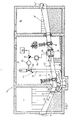
- the culvert arrangement 9 shown in FIG. 1 has a culvert forward shaft 11, a measuring and throttle shaft 12 and a culvert downstream shaft 13.
- a culvert upstream culvert inlet structure
- an upwardly open channel or channel 8 ⁇ opens out, which leads to a further sewer pipe 14 ⁇ .
- This culvert arrangement 9 is connected to a sewer pipe 14 Wastewater sewerage connected and used to drain the wastewater to a further sewage system, which can lead to a sewage treatment plant, other rainwater retention or the like.
- the channel 8 ⁇ lead obliquely upwards with a relatively small slope.
- the minimum water level in the culvert arrangement 9 is indicated by the dotted line 15. There is no flow through him anymore.
- the drain pipe 10 is flowed through by waste water in the direction of arrow A, the flow rate of which is measured by means of a magnetic inductive flow meter 16 which measures the flow at the illustrated point of the drain pipe 10, where this is always completely filled with waste water, this point being between two throttle valves 17, 18.
- jet pipes 21, 22, 23 of a jet cleaning device 29 open into the drain pipe 10.
- these jet pipes are straight, circular-cylindrical rigid pipes, the outlet openings for flushing water-forming outlet openings 24, 25, 26 are flush with the inner wall of the peripheral wall of the drain pipe 10, as is particularly evident for the outlet 25 in FIG. 2 sees which mouths do not protrude into the interior of the drain pipe 10 and thus do not form any flow obstacles in the drain pipe 10.
- the jet pipes 21-23 are arranged obliquely to the longitudinal direction of the drain pipe in their area as shown so that the strong rinsing water jets flowing from them according to arrows B exert such thrust or momentum on the waste water in the drain pipe 10, which in each case also in vectorial decomposition has a vectorial component v F directed in the direction of flow of the wastewater, so that the strong jets of flushing water push the wastewater in the direction of its flow and are also driving jets for the wastewater, which support its flow in the direction of flow (arrow A).
- the jet pipe 22 opens at the deepest point in the drain pipe 10 and the other two jet pipes 21, 23 also open into the lower circumferential half of the drain pipe, but are seen from the lowest point of the drain pipe by about 30 to 45 ° in the circumferential direction of the round drain pipe 10 to the left and right as shown angularly offset and the outlet openings are also offset in the longitudinal direction of the drain pipe 10 as shown, so that the outlet opening 24 is still in the steep downward region 27 and the outlet opening 26 in the flat rising region 28 of the Drain pipe 10 is located.
- the inclination of the jet direction B of the individual jet pipe 21, 22, 23 to the longitudinal axis of the relevant area of the drain pipe 10 is approximately 40 to 50 ° in this exemplary embodiment. This angle can also be larger or smaller.
- the jet directions of these jet pipes 21, 22, 23 can be approximately directed towards the longitudinal axis of the drain pipe 10 or often pass particularly cheaply at a distance from this longitudinal axis. It is particularly favorable if the water jets flowing out of these jet pipes 21, 22, 23 in the drain pipe generate a swirl flow towards the downstream end of the drain pipe, but other flow patterns can also be provided. It is essential that the rinse water jets in the drain pipe 10 remove sludge and other impurities collected in it cause in the flow direction A of the waste water 10.
- rinsing water jets whirl up the relevant impurities from the bottom of the drain pipe and cause them to float in the wastewater that then sweeps them away, and the rinsing water jets cause sufficient outflow of sewage from the drain pipe even at low flow rates of the sewage.
- the rinsing water jets can also rinse off coarse contaminants, such as branches or the like.
- the rinsing water jets can also generate strong turbulence which further promotes the cleaning of the drain pipe 10 and can also be "reflected" several times on the pipe wall and thus also deflected to the bottom of the drain pipe in the case of the jet directions shown. If necessary, you can also point at least one jet pipe directly to the bottom of the drain pipe.
- the outlet openings 24, 25, 26 are arranged at the lowest and near the lowest region 20 of the drain pipe 10.
- At least one jet pipe is arranged at a short distance from this flow measuring point in front of or behind it and is directed towards it.
- At least one jet pipe can be arranged on the upper circumferential half of the drain pipe 10 and then preferably its jet direction can be directed obliquely downward in the flow direction of the waste water, as is shown in dash-dot lines in FIG. 2 as an example of a jet pipe 21 ⁇ .
- At least one jet pipe radiates the flushing water into the drain pipe 10 in such a way that the inflow speed of the flushing water has an essential speed component which is tangential to the inner peripheral wall of the drain pipe 10 and another speed component runs along a surface line of the drain pipe, preferably in the flow direction of the waste water.
- the jet pipes 21, 22, 23 are connected to a common pressurized water supply line 31.
- a shut-off valve 32 is inserted into this feed line and can be opened and closed by an actuator 33. This is controlled by a timer or program control device 34 for opening and locking. E.g. can be provided that the shut-off valve 32 is opened at intervals of one hour for one minute each to introduce jets of flushing water through the jet pipes 21, 22, 23 into the drain pipe 10.
- an on-off switch 35 is interposed, which is always opened by an actuator 36 as long as the flow meter 16 feels that the flow is above a predetermined limit, above which there is no disturbing amount in the drain pipe Contaminants such as sand, mud or the like can settle. As long as the flow falls below this limit, the switch 35 is closed and so is it briefly rinsing the drain pipe 10 by means of the rinse water jets takes place automatically in the predetermined time intervals.
- each jet pipe 21, 22, 23, can each have their own valve 32a, 32b, 32c, which can be opened and shut off by an actuator 33a, 33b, 33c,
- one solenoid valve each can be assigned and these valves 32a, 32b and 32c can then be opened and shut off at different times relative to one another, be it by hand or preferably by means of a timer or program control device 34 ⁇ , the separate outputs for independently controlling the Actuators 33a, 33b and 33c.
- These beam tubes can then also be opened and shut off at different times, for example in sequence, or in overlapping time intervals or in some other way at different times or, if desired, also together.
- the drain pipe 28 of the culvert arrangement 9 can optionally also extend from the pipe 14 to the pipe 14 ⁇ .
Landscapes
- Health & Medical Sciences (AREA)
- Life Sciences & Earth Sciences (AREA)
- Engineering & Computer Science (AREA)
- Hydrology & Water Resources (AREA)
- Public Health (AREA)
- Water Supply & Treatment (AREA)
- Cleaning In General (AREA)
- Sink And Installation For Waste Water (AREA)
Applications Claiming Priority (2)
| Application Number | Priority Date | Filing Date | Title |
|---|---|---|---|
| DE3617293 | 1986-05-23 | ||
| DE3617293 | 1986-05-23 |
Publications (4)
| Publication Number | Publication Date |
|---|---|
| EP0246562A2 true EP0246562A2 (fr) | 1987-11-25 |
| EP0246562A3 EP0246562A3 (en) | 1988-01-20 |
| EP0246562B1 EP0246562B1 (fr) | 1990-12-27 |
| EP0246562B2 EP0246562B2 (fr) | 1994-08-10 |
Family
ID=6301424
Family Applications (1)
| Application Number | Title | Priority Date | Filing Date |
|---|---|---|---|
| EP87107016A Expired - Lifetime EP0246562B2 (fr) | 1986-05-23 | 1987-05-14 | Procédé et dispositif pour la modification de l'écoulement d'un égout |
Country Status (2)
| Country | Link |
|---|---|
| EP (1) | EP0246562B2 (fr) |
| DE (2) | DE3716204C2 (fr) |
Cited By (3)
| Publication number | Priority date | Publication date | Assignee | Title |
|---|---|---|---|---|
| FR2861762A1 (fr) * | 2003-11-04 | 2005-05-06 | Ksb Sas | Procede de curage d'une canalisation et groupe motopompe particulierement adapte a ce procede |
| WO2016207716A1 (fr) * | 2015-06-26 | 2016-12-29 | Dyteqta Limited | Dispositif de nettoyage de tuyau de drainage et procédé de nettoyage |
| EP3467217A4 (fr) * | 2016-05-23 | 2019-06-26 | Ning, Xiaoying | Accélérateur de flux d'eau |
Families Citing this family (6)
| Publication number | Priority date | Publication date | Assignee | Title |
|---|---|---|---|---|
| DE3743703C2 (de) * | 1987-12-23 | 1997-10-23 | Vollmar Oskar Gmbh | Verfahren zum automatischen Reinigen eines gedükerten Abwasserrohres |
| DE4429288C2 (de) * | 1994-08-18 | 1997-09-11 | Hans Dipl Ing Geiger | Verfahren und Vorrichtung zur Sauberhaltung von Bach- und Abwasserdükern |
| RO123560B1 (ro) * | 2005-12-29 | 2013-09-30 | Doru Cornel Sava | Instalaţie de canalizare |
| DE102006041482B3 (de) * | 2006-09-02 | 2008-01-03 | Jung Pumpen Gmbh | Verfahren zum Spülen einer Druckrohrleitung und Abwasserfördervorrichtung |
| DE202013004552U1 (de) | 2013-05-16 | 2013-06-24 | Eberhard Wendt | Dükeranlage |
| RU2770881C1 (ru) * | 2021-10-14 | 2022-04-25 | Федеральное государственное бюджетное образовательное учреждение высшего образования "Санкт-Петербургский государственный архитектурно-строительный университет" | Узел регулирования воздушной подушки на участках канализационной сети дюкерного типа |
Family Cites Families (6)
| Publication number | Priority date | Publication date | Assignee | Title |
|---|---|---|---|---|
| DE362026C (de) * | 1922-10-19 | Gewerkschaft Hausbach O | Kanalisationsrohr mit Druckwasserspuelung | |
| DE296738C (fr) * | 1915-01-05 | 1917-02-27 | ||
| FR1563231A (fr) * | 1968-02-29 | 1969-04-11 | ||
| FR2278412A1 (fr) * | 1974-07-17 | 1976-02-13 | Cama Michel | Dispositif de nettoyage de vide-ordures |
| SE416981B (sv) * | 1979-06-11 | 1981-02-16 | Nils Gosta Ragnar Nilsson | Sett och anordning for rensning av dykarledning |
| DE2944733A1 (de) * | 1979-11-06 | 1981-05-14 | Fa. Oskar Vollmar, 7000 Stuttgart | Verfahren und anlage zur dosierung des wasserabflusses aus einem regenbecken |
-
1987
- 1987-05-14 DE DE3716204A patent/DE3716204C2/de not_active Expired - Fee Related
- 1987-05-14 DE DE8787107016T patent/DE3767026D1/de not_active Expired - Fee Related
- 1987-05-14 EP EP87107016A patent/EP0246562B2/fr not_active Expired - Lifetime
Cited By (6)
| Publication number | Priority date | Publication date | Assignee | Title |
|---|---|---|---|---|
| FR2861762A1 (fr) * | 2003-11-04 | 2005-05-06 | Ksb Sas | Procede de curage d'une canalisation et groupe motopompe particulierement adapte a ce procede |
| EP1529889A1 (fr) * | 2003-11-04 | 2005-05-11 | Ksb S.A.S | Procédé de curage d'une canalisation et groupe motopompe particulièrement adapté à ce procédé |
| WO2016207716A1 (fr) * | 2015-06-26 | 2016-12-29 | Dyteqta Limited | Dispositif de nettoyage de tuyau de drainage et procédé de nettoyage |
| CN107847988A (zh) * | 2015-06-26 | 2018-03-27 | 迪泰克塔有限公司 | 排水管清洁装置和清洁方法 |
| US10843237B2 (en) | 2015-06-26 | 2020-11-24 | Dyteqta International Limited | Drain pipe cleaning device and method of cleaning |
| EP3467217A4 (fr) * | 2016-05-23 | 2019-06-26 | Ning, Xiaoying | Accélérateur de flux d'eau |
Also Published As
| Publication number | Publication date |
|---|---|
| DE3767026D1 (de) | 1991-02-07 |
| DE3716204A1 (de) | 1987-11-26 |
| DE3716204C2 (de) | 1994-03-24 |
| EP0246562B1 (fr) | 1990-12-27 |
| EP0246562A3 (en) | 1988-01-20 |
| EP0246562B2 (fr) | 1994-08-10 |
Similar Documents
| Publication | Publication Date | Title |
|---|---|---|
| EP3515784B1 (fr) | Dispositif de traitement d'eaux grises pour véhicules ferroviaires | |
| DE69831577T2 (de) | Verfahren und vorrichtung zur schlammabführung | |
| EP0246562B1 (fr) | Procédé et dispositif pour la modification de l'écoulement d'un égout | |
| DE102018110633A1 (de) | Abscheidungseinrichtung zum Entfernen von Gegenständen aus einem Wasserstrom und Verfahren für den Betrieb einer solchen Abscheidungseinrichtung | |
| EP0918913B1 (fr) | Dispositif pour nettoyage de cuves contenant du liquide en conditions de service et utilisation de ce dispositif dans une chambre de laveur | |
| EP1226316B1 (fr) | Procede et dispositif pour rincer periodiquement une canalisation d'eau usee | |
| DE8706967U1 (de) | Einrichtung zur Verbesserung des Durchflusses eines Abflußrohres | |
| DE4038622C2 (de) | Verfahren und Anlage zum Reinigen eines Regenbeckens | |
| DE1274044B (de) | In einen Abwasserkanal eingeschaltetes Ausgleichs- und Absetzbecken fuer Regenwassermit einer in einen Vorfluter entwaessernden UEberlaufrinne | |
| DE954947C (de) | Siebeinrichtung fuer mit Schwimm- und Grobstoffen verunreinigte Waesser, insbesondere fuer Abwasserreinigungsanlagen | |
| EP0280648B1 (fr) | Dispositif de nettoyage pour réservoirs d'épuration des eaux usées | |
| DE102020122940A1 (de) | Regenkläranlage und Regenkläreinrichtung | |
| DE19820259A1 (de) | Vorrichtung zum Reinigen, Spülen und Waschen eines Abwasserstromes in einem Zulaufgerinne einer Kläranlage | |
| DE19741898A1 (de) | Filtervorrichtung für Regenwasserzisternen | |
| AT384849B (de) | Verfahren und einrichtung zur unterflurbewaesserung | |
| DE4006925A1 (de) | Klaer- oder absetzbecken | |
| DE4015577C2 (de) | Verfahren zum Reinigen eines Wasserbeckens, insbesondere Regenbeckens einer Mischkanalisation | |
| DE10115019B4 (de) | Regenwasserfilter mit einem Filtergehäuse und Verfahren zum Reinigen eines Regenwasserfilters | |
| AT136739B (de) | Einrichtung zur Wegschaffung von Sinkstoffen aus Klärräumen, Stauwerken u. dgl. | |
| DE801720C (de) | Vorrichtung zum Entwaessern und Entschlaemmen von Pressluftleitungen, insbesondere im Bergbau | |
| DE853418C (de) | Verfahren und Vorrichtung zum Beschicken von Arbeitsmaschinen, insbesondere Steinsaegegattern, mit Wasser und Sand und zu deren Rueckgewinnung und Wiederverwendung | |
| DE3503509A1 (de) | Fluessigkeitsspeicherraum mit einer spueleinrichtung | |
| DE19731264A1 (de) | Wasserabzug an Abzugbecken | |
| EP0577548A1 (fr) | Siphon pour égouts | |
| DE2900566C3 (de) | Rückhaltebecken, insbesondere in Mischwasserkanalisationen |
Legal Events
| Date | Code | Title | Description |
|---|---|---|---|
| PUAI | Public reference made under article 153(3) epc to a published international application that has entered the european phase |
Free format text: ORIGINAL CODE: 0009012 |
|
| AK | Designated contracting states |
Kind code of ref document: A2 Designated state(s): DE |
|
| PUAL | Search report despatched |
Free format text: ORIGINAL CODE: 0009013 |
|
| AK | Designated contracting states |
Kind code of ref document: A3 Designated state(s): DE |
|
| 17P | Request for examination filed |
Effective date: 19880429 |
|
| 17Q | First examination report despatched |
Effective date: 19881209 |
|
| GRAA | (expected) grant |
Free format text: ORIGINAL CODE: 0009210 |
|
| AK | Designated contracting states |
Kind code of ref document: B1 Designated state(s): DE |
|
| REF | Corresponds to: |
Ref document number: 3767026 Country of ref document: DE Date of ref document: 19910207 |
|
| PLBI | Opposition filed |
Free format text: ORIGINAL CODE: 0009260 |
|
| 26 | Opposition filed |
Opponent name: EGNER GMBH & CO. Effective date: 19910921 |
|
| PLAB | Opposition data, opponent's data or that of the opponent's representative modified |
Free format text: ORIGINAL CODE: 0009299OPPO |
|
| R26 | Opposition filed (corrected) |
Opponent name: EGNER GMBH & CO. Effective date: 19910921 |
|
| PLAB | Opposition data, opponent's data or that of the opponent's representative modified |
Free format text: ORIGINAL CODE: 0009299OPPO |
|
| R26 | Opposition filed (corrected) |
Opponent name: EGNER GMBH & CO. Effective date: 19910921 |
|
| PUAH | Patent maintained in amended form |
Free format text: ORIGINAL CODE: 0009272 |
|
| STAA | Information on the status of an ep patent application or granted ep patent |
Free format text: STATUS: PATENT MAINTAINED AS AMENDED |
|
| 27A | Patent maintained in amended form |
Effective date: 19940810 |
|
| AK | Designated contracting states |
Kind code of ref document: B2 Designated state(s): DE |
|
| PGFP | Annual fee paid to national office [announced via postgrant information from national office to epo] |
Ref country code: DE Payment date: 19960522 Year of fee payment: 10 |
|
| PG25 | Lapsed in a contracting state [announced via postgrant information from national office to epo] |
Ref country code: DE Free format text: LAPSE BECAUSE OF NON-PAYMENT OF DUE FEES Effective date: 19980203 |