EP0246710A1 - Presse pour pellets - Google Patents
Presse pour pellets Download PDFInfo
- Publication number
- EP0246710A1 EP0246710A1 EP87200941A EP87200941A EP0246710A1 EP 0246710 A1 EP0246710 A1 EP 0246710A1 EP 87200941 A EP87200941 A EP 87200941A EP 87200941 A EP87200941 A EP 87200941A EP 0246710 A1 EP0246710 A1 EP 0246710A1
- Authority
- EP
- European Patent Office
- Prior art keywords
- pressing roll
- adjustment
- pelletizer
- main shaft
- pressing
- Prior art date
- Legal status (The legal status is an assumption and is not a legal conclusion. Google has not performed a legal analysis and makes no representation as to the accuracy of the status listed.)
- Granted
Links
- 238000003825 pressing Methods 0.000 claims description 65
- 125000006850 spacer group Chemical group 0.000 claims description 12
- 241001275902 Parabramis pekinensis Species 0.000 claims description 3
- 230000000284 resting effect Effects 0.000 description 2
- 238000007789 sealing Methods 0.000 description 2
- 102000004726 Connectin Human genes 0.000 description 1
- 108010002947 Connectin Proteins 0.000 description 1
- 238000005056 compaction Methods 0.000 description 1
- 238000010276 construction Methods 0.000 description 1
- 230000000694 effects Effects 0.000 description 1
- 238000005461 lubrication Methods 0.000 description 1
- 238000012423 maintenance Methods 0.000 description 1
- 238000000034 method Methods 0.000 description 1
- 238000005453 pelletization Methods 0.000 description 1
Images


Classifications
-
- B—PERFORMING OPERATIONS; TRANSPORTING
- B30—PRESSES
- B30B—PRESSES IN GENERAL
- B30B11/00—Presses specially adapted for forming shaped articles from material in particulate or plastic state, e.g. briquetting presses, tabletting presses
- B30B11/20—Roller-and-ring machines, i.e. with roller disposed within a ring and co-operating with the inner surface of the ring
- B30B11/201—Roller-and-ring machines, i.e. with roller disposed within a ring and co-operating with the inner surface of the ring for extruding material
- B30B11/208—Roller constructions; Mounting of the rollers
-
- Y—GENERAL TAGGING OF NEW TECHNOLOGICAL DEVELOPMENTS; GENERAL TAGGING OF CROSS-SECTIONAL TECHNOLOGIES SPANNING OVER SEVERAL SECTIONS OF THE IPC; TECHNICAL SUBJECTS COVERED BY FORMER USPC CROSS-REFERENCE ART COLLECTIONS [XRACs] AND DIGESTS
- Y10—TECHNICAL SUBJECTS COVERED BY FORMER USPC
- Y10S—TECHNICAL SUBJECTS COVERED BY FORMER USPC CROSS-REFERENCE ART COLLECTIONS [XRACs] AND DIGESTS
- Y10S425/00—Plastic article or earthenware shaping or treating: apparatus
- Y10S425/23—Hay wafering or pelletizing means
Definitions
- This invention relates to a pelletizer comprising an annular drivable press mold mounted on a stationary main shaft within a frame and pressing rolls provided within said mold and mounted in bearing journals and drivable by said press mold, the shafts of said pressing rolls being eccentric relatively to said bearing journals, there being provided an adjustment device for varying the position of the pressing roll shaft.
- a similar pelletizer is known e.g. from Dutch patent 139,111. Adjustment of the pressing rolls in the direction of the inner surface of the press mold takes place manually herein. To that end, a hexagonal shoulder is disposed on a bearing journal of each pressing roll, on which shoulder can be placed a nut spanner.
- a second drawback of the adjustment of the pressing roll by hand is that this can take place only with an inoperative pelletizer.
- a major drawback is further that the correct setting of the pressing roll relatively to the mold can be obtained with the trial and error method only, since the correct setting of the pressing roll can only be determined experimentally with the pressed product. In fact, this correct placement depends upon the material to be processed by the pelletizer.
- the pelletizer according to the present invention is characterized to that end in that the adjustment device includes at least one hydraulic adjustment cylinder whose ends are connected to the bearing journals of the pressing roll shafts, while the oil supply and discharge pipes of each hydraulic adjustment cylinder extend through the main shaft of the pelletizer.
- each pressing roll is adjustable by means of an associated hydraulic adjustment cylinder whose piston rod engages with the adjustment crank of the pressing roll and the other end is fixedly connected to a stationary spacer plate provided within the press mold.
- Hydraulic adjustment of the pressing rolls has the advantage that adjustment of the pressing rolls can take place when the pelletizer is in operation, while, moreover, the pressure supplied to adjustment cylinder is indicative of the force with which the outer surface of the pressing roll presses against the inner surface of the annular mold.
- the pressure supplied to adjustment cylinder is indicative of the force with which the outer surface of the pressing roll presses against the inner surface of the annular mold.
- each pressing roll is provided with a hydraulic clamping device for fixing the roll in a given position after its adjustment.
- a hydraulic clamping device consists of a tie rod extending coaxially with the bearing journals through the pressing roll, said tie rod being provided on the main shaft end with a cup-shaped nut whose edge can be pressed against wedge-shaped bearing brasses mounted about the bearing journal of a pressing roll, while at the other side of the pressing roll there is provided a hydraulic operated servo piston on said tie rod through which the tie rod can be subjected to a tensile load.
- the stroke of the hydraulic cylinder is usually smaller than the admissible wear of the surfaces of the pressing rolls and the annular mold, it is desirable to have the possibility of adapting the adjustment range to the extent of wear ocurred in the course of time.
- the bearing journal of the pressing roll shaft remote from the main shaft is provided to that end with a polygonal shoulder, while the adjustment crank is provided internally with a correspondingly formed cut-out, the arrangement being such that said adjustment crank can be placed on said polygonal shoulder in different positions.
- the magnitude of the adjustment range of the pressing roll is determined by the extent of eccentricity of the pressing roll shaft.
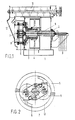
- Figs.1 and 2 shown the main components of the pelletizer, consisting of a frame 1 wherein is mounted a main shaft 2 in stationary relationship. On said main shaft 2 is mounted a mold holder 3 to which is attached an annular mold 5. Mold holder 3 is connected to a drive wheel 4 driven by a motor, not shown, by means of vee ropes. Within annular mold 5 are provided two pressing rolls 6 mounted on the one hand in main shaft 2 and on the other hand in a spacer plate 7 connected to said main shaft 2 by means of two rods. Mounted on said spacer plate 7 are two hydraulic adjustment cylinders 8, one for each pressing roll 6. The construction and operation thereof will be further explained hereinafter on the basis of Fig.4.
- Each pressing roll 6 is provided with a hydraulic clamping device to be explained hereinafter on the basis of Fig. 3.
- a material supply device 11 resting on frame 1 of the pelletizer, said device including a diagrammatically shown transport/mixing mechanism supplying the material to be processed to a feed hopper 12 connected to the annular mold 5.
- the grains compacted by the annular mold are discharged via a chute at the bottom of mold 5.
- the hydraulic clamping device (Fig.3)
- Fig.3 shows the pressing roll 6 abutting against the annular press mold 5 mounted, via the partly shown mold holder 3 in frame 1 of the pelletizer on the main shaft also partly shown.
- Pressing roll 6 is mounted on the pressing roll shaft 13 by means of roller bearings 14, the axis of said shaft 13 being indicated at X.
- Said shaft 13 is placed eccentrically relatively to the two bearing journals 16,22, journal 16 being placed in a cut-out in the stationary main shaft 2, with journal 22 resting in a cut-out provided in spacer plate 7.
- Through journals 16,22 extends a tie rod 18 projecting from spacer plate 7.
- journal 22 Mounted on journal 22 is a polygonal shoulder 23, the function of which will be explained hereinafter.
- a cap 24 On to the left end of tie rod 18 is screwed a cap 24 wherein is recessed a chamber 26 accommodating a servo piston 25. Cap 24 is held down by means of a nut 27 provided on the end of tie rod 18.
- the side walls of pressing roll 6 are provided with sealing plates 15.
- the hydraulic clamping device is operated as follows:
- the polygonal shoulder 23, connected to journal 22, is the rotated, so that the eccentric pressing roll shaft 13 occupies a different position and the circumferential surface of roll 6 comes to lie closer to or remoter from the inner wall of mold 5.
- pressure is supplied to chamber 26 between cap 24 and servo piston 25.
- Servo piston 25 is thereby pressed to the right until it abuts against the polygonal shoulder 23.
- Cap 24 is pressed to the left in Fig. 3, exerting a tensile force on tie rod 18.
- the wedge-shaped clamping segments 20 of cup-shaped nut 17 are pressed onto each other, thus ensuring a clamping of journal 16 in the stationary main shaft 2. Pressing roll 6 is thus clamped in the newly adjusted position.
- the adjustment device for the pressing roll (Fig.4).
- Fig. 4 shows a front view of the spacer plate 7 on which only one adjustment cylinder 8 is mounted, for the sake of clarity.
- the one end of adjustment cylinder 8 is pivotally mounted on an attachment journal 32 fixedly connected to spacer plate 7.
- a piston rod 33 whose free end is connected to a crank 39, being polygonal internally so as to fit on the polygonal shoulder 23 connected to the journal 22 of pressing roll shaft 13 (see also Fig.3).
- Piston rod 33 is shown in the most retracted position in adjustment cylinder 8, while the position shown of crank 39 pertains to the most extended position of piston rod 33.
- Adjustment cylinder 8 is provided with two oil inlets 34,35 for moving the piston of adjustment cylinder 8 in the desired direction.
- spacer plate 7 Shown at the underside of spacer plate 7 are three oil pipes 36, 37, 38, two of which are connected to the inlets 34,35 of adjustment cylinder 8, oil pipe 38 being connected to chamber 26 of servo piston 25 shown in Fig. 3 for operating the clamping device.
- Spacer plate 7 is connected with two attaching rods 30,31 to the front face of main shaft 2.
- Piston rod 33 of adjustment cylinder 8 is pivotally connected to adjustment crank 39 by means of a connecting pin 40 suitably secured in the crank by means of a split pin 41.
- Adjustment cylinder 8 is adapted to swivel adjustment crank 39 through an angle of about 70°.
- the circumference of the pressing roll 6 can thus be displaced along a distance of X mm in the direction of the inner circumference of the press mold. Because, during pelletizing material, pressing rolls 6 may be subjected to more wear than X mm, at the outer surface and mold 5 at the inner surface, the position of adjustment crank 39 relative to the polygonal shoulder 23 should be variable.
- the polygonal shoulder 23 is dodecagonal externally, which also applies to adjustment crank 39, be it internally. Consequently, crank 39 can be placed in twelve positions on the polygonal shoulder 23 so that there is an ample choice for the desired adjustment range of the pressing rolls.
- the second pressing roll is adjusted identically by means of an identical adjustment cylinder 8 mounted on spacer plate 7 inversely-symmetrically relative to the adjustment cylinder shown in Fig. 4.
- Fig. 1 shows in dotted lines at the right end of the pelletizer oil pipes which subsequently extend horizontally through main shaft 2.
- the connectin of the oil pipes to the pelletizer is shown in more detail in Fig. 5.
- main shaft 2 is stationary, but in the case of seizure of the pelletizer, may be entrained by the mold 5, the different oil pipes have to be connected to main shaft 2 by means of slip rings. If this were not the case, all hydraulic pipes would be fractured in the event of seizure of the pelletizer and rotation of the main shaft.
- na extension piece 2 ⁇ of smaller diameter wherein is provided a central oil channel and eight oil pipes uniformly distributed over a circle, two of which are indicated in Fig.5B at 45,46. Except the central oil pipe , the eight other oil pipes are plugged at the end of main shaft 2 ⁇ .
- Pipe 45 terminates in an annular channel of slip ring 42 sealed on both ends by seals 44.
- Channel 46 terminates in an annular oil channel of slip ring 43 sealed identically. All other oil channels provided in shaft 2 ⁇ are connected identically to the slip rings further indicated diagrammatically.
- each oil pipe 45,46 etc. is connected through by-passes 47 to corresponding oil channels such as 45 ⁇ provided in the main shaft.
- Fig. 5A shows the course of the oil pipes in main shaft 2 ⁇ , as well as the course of the associated pipes in main shaft 2.
- Three oil pipes serve for the lubrication of the main bearing and of the bearings of the pressing rolls 6.
- Two oil pipes extend towards each adjustment cylinder 8, while for each clamping device 10 an oil pipe is also passed from the connection point on shaft 2 ⁇ through main shaft 2 to spacer plate 7.
Landscapes
- Engineering & Computer Science (AREA)
- Mechanical Engineering (AREA)
- Processing And Handling Of Plastics And Other Materials For Molding In General (AREA)
- Press Drives And Press Lines (AREA)
Applications Claiming Priority (2)
| Application Number | Priority Date | Filing Date | Title |
|---|---|---|---|
| NL8601270 | 1986-05-20 | ||
| NL8601270A NL8601270A (nl) | 1986-05-20 | 1986-05-20 | Korrelpers. |
Publications (3)
| Publication Number | Publication Date |
|---|---|
| EP0246710A1 true EP0246710A1 (fr) | 1987-11-25 |
| EP0246710B1 EP0246710B1 (fr) | 1990-09-05 |
| EP0246710B2 EP0246710B2 (fr) | 1994-03-09 |
Family
ID=19848035
Family Applications (1)
| Application Number | Title | Priority Date | Filing Date |
|---|---|---|---|
| EP87200941A Expired - Lifetime EP0246710B2 (fr) | 1986-05-20 | 1987-05-19 | Presse pour pellets |
Country Status (5)
| Country | Link |
|---|---|
| US (1) | US4838779A (fr) |
| EP (1) | EP0246710B2 (fr) |
| DE (1) | DE3764710D1 (fr) |
| DK (1) | DK166440B1 (fr) |
| NL (1) | NL8601270A (fr) |
Cited By (4)
| Publication number | Priority date | Publication date | Assignee | Title |
|---|---|---|---|---|
| EP0371519A3 (fr) * | 1986-01-24 | 1991-07-24 | Buehler Ag | Presse à granuler |
| EP0594278A1 (fr) * | 1992-10-19 | 1994-04-27 | California Pellet Mill Company | Dispositif et méthode d'ajustement des rouleaux dans une presse à extruder des granulés |
| EP0773101A3 (fr) * | 1995-10-31 | 1998-02-04 | CPM/Europe B.V. | Presse à granuler |
| CN115121181A (zh) * | 2022-07-12 | 2022-09-30 | 广西力源宝科技有限公司 | 简化快速换模挤压造粒机 |
Families Citing this family (11)
| Publication number | Priority date | Publication date | Assignee | Title |
|---|---|---|---|---|
| US5792485A (en) * | 1989-08-21 | 1998-08-11 | Korse; Theodorus H. | Pelleting press |
| US5251545A (en) * | 1990-08-20 | 1993-10-12 | Buhler Ag | Method for slip regulation of a pellet mill and apparatus for carrying out the process |
| NL9200874A (nl) * | 1992-05-18 | 1993-12-16 | Benthum A P T Beheer Bv | Kneedapparaat. |
| NL1004319C2 (nl) * | 1996-10-18 | 1998-04-21 | Pelleting Technologie Nederlan | Pelleteerpers. |
| US20050230872A1 (en) * | 2004-03-26 | 2005-10-20 | Scobee Robert E | Pellet mill and method of making peanut hull granules |
| KR101266944B1 (ko) | 2010-12-28 | 2013-05-30 | (주) 기홍 | 고형연료 제조용 성형기 |
| NL2006036C2 (nl) * | 2011-01-20 | 2012-07-23 | Cpm Europ B V | Pelleteerinrichting. |
| US8974710B2 (en) | 2011-04-29 | 2015-03-10 | Andritz Ag | Pellet mill having improved construction |
| EP2517869A1 (fr) | 2011-04-29 | 2012-10-31 | Andritz AG | Presse à agglomérer |
| EP2701899B1 (fr) | 2011-04-29 | 2015-06-03 | Andritz AG | Granulateur équipé d'un système d'alimentation et procédé de formation de granulés |
| FR3129614A1 (fr) | 2021-11-29 | 2023-06-02 | Commissariat A L'energie Atomique Et Aux Energies Alternatives | Installation et procédé afférent de production de granulés de biomasse hydrophobes. |
Citations (4)
| Publication number | Priority date | Publication date | Assignee | Title |
|---|---|---|---|---|
| US2240660A (en) * | 1940-02-26 | 1941-05-06 | Edgar T Meakin | Extrusion mill |
| GB989603A (en) * | 1963-09-30 | 1965-04-22 | Muhlenbau Dresden Veb | Pressure-application device |
| US3354845A (en) * | 1964-06-26 | 1967-11-28 | Buehler Ag Geb | A pellet mill having adjustably mounted rollers |
| US3679343A (en) * | 1970-05-04 | 1972-07-25 | California Pellet Mill Co | Extrusion mill with roller adjustment means |
Family Cites Families (4)
| Publication number | Priority date | Publication date | Assignee | Title |
|---|---|---|---|---|
| US3207090A (en) * | 1962-11-19 | 1965-09-21 | Cunningham & Sons | Adjustable pressure pelleting machine |
| CH454592A (de) * | 1966-03-23 | 1968-04-15 | Buehler Ag Geb | Futterwürfelpresse |
| US3551950A (en) * | 1968-08-12 | 1971-01-05 | Japan Gas Chemical Co | Pellet mill for wet powdery materials |
| DE3775423D1 (en) * | 1986-01-24 | 1992-02-06 | Buehler Ag | Wuerfelpresse. |
-
1986
- 1986-05-20 NL NL8601270A patent/NL8601270A/nl not_active Application Discontinuation
-
1987
- 1987-05-15 US US07/050,926 patent/US4838779A/en not_active Expired - Fee Related
- 1987-05-19 EP EP87200941A patent/EP0246710B2/fr not_active Expired - Lifetime
- 1987-05-19 DE DE8787200941T patent/DE3764710D1/de not_active Expired - Fee Related
- 1987-05-20 DK DK256487A patent/DK166440B1/da not_active IP Right Cessation
Patent Citations (4)
| Publication number | Priority date | Publication date | Assignee | Title |
|---|---|---|---|---|
| US2240660A (en) * | 1940-02-26 | 1941-05-06 | Edgar T Meakin | Extrusion mill |
| GB989603A (en) * | 1963-09-30 | 1965-04-22 | Muhlenbau Dresden Veb | Pressure-application device |
| US3354845A (en) * | 1964-06-26 | 1967-11-28 | Buehler Ag Geb | A pellet mill having adjustably mounted rollers |
| US3679343A (en) * | 1970-05-04 | 1972-07-25 | California Pellet Mill Co | Extrusion mill with roller adjustment means |
Cited By (4)
| Publication number | Priority date | Publication date | Assignee | Title |
|---|---|---|---|---|
| EP0371519A3 (fr) * | 1986-01-24 | 1991-07-24 | Buehler Ag | Presse à granuler |
| EP0594278A1 (fr) * | 1992-10-19 | 1994-04-27 | California Pellet Mill Company | Dispositif et méthode d'ajustement des rouleaux dans une presse à extruder des granulés |
| EP0773101A3 (fr) * | 1995-10-31 | 1998-02-04 | CPM/Europe B.V. | Presse à granuler |
| CN115121181A (zh) * | 2022-07-12 | 2022-09-30 | 广西力源宝科技有限公司 | 简化快速换模挤压造粒机 |
Also Published As
| Publication number | Publication date |
|---|---|
| DE3764710D1 (de) | 1990-10-11 |
| DK256487A (da) | 1987-11-21 |
| NL8601270A (nl) | 1987-12-16 |
| DK166440B1 (da) | 1993-05-24 |
| EP0246710B2 (fr) | 1994-03-09 |
| DK256487D0 (da) | 1987-05-20 |
| US4838779A (en) | 1989-06-13 |
| EP0246710B1 (fr) | 1990-09-05 |
Similar Documents
| Publication | Publication Date | Title |
|---|---|---|
| EP0246710A1 (fr) | Presse pour pellets | |
| US4119032A (en) | Printing press with removable printing roll sleeve | |
| DE69802945T2 (de) | Bodenherstellung | |
| WO1982000165A1 (fr) | Cylindre de compression, dont la flexion est reglable | |
| US4782749A (en) | Screw press with an actuator | |
| ES2005247A6 (es) | Dispositivo en una prensa con arbol de excentrica para regular lacarrera del portamachos | |
| CN101091930A (zh) | 辊轧机 | |
| EP0594278B1 (fr) | Dispositif et méthode d'ajustement des rouleaux dans une presse à extruder des granulés | |
| JP3464224B2 (ja) | ロール | |
| US4637109A (en) | Controlled deflection roller | |
| US20240091784A1 (en) | High-pressure roller press | |
| DK0634217T3 (da) | Slidfast panseroverfladebelægning til valserne på højtryksvalsepresser og fremgansmåde til opbygningaf en sådan valsepansring | |
| CA2064858C (fr) | Presse a agglomerer | |
| US4179257A (en) | Press | |
| US3456993A (en) | Sliding bearing with pneumatically or hydraulically pressed bearing cups | |
| US2687257A (en) | Gyratory crusher | |
| US4925382A (en) | Roller press for compacting fine-grained salts into sheets | |
| EP1534499A1 (fr) | Presse a cuber | |
| DE3441305C2 (fr) | ||
| US3459383A (en) | Clamping and release means for crusher bowls | |
| DE3041267A1 (de) | Drueckmaschine | |
| RU1796249C (ru) | Мельница | |
| CN214933560U (zh) | 新型皮带输送机刮浆器 | |
| EP0396199B1 (fr) | Presse à agglomérer pour aliments et analogues | |
| FI59344C (fi) | Konkross |
Legal Events
| Date | Code | Title | Description |
|---|---|---|---|
| PUAI | Public reference made under article 153(3) epc to a published international application that has entered the european phase |
Free format text: ORIGINAL CODE: 0009012 |
|
| AK | Designated contracting states |
Kind code of ref document: A1 Designated state(s): BE CH DE FR GB IT LI NL |
|
| 17P | Request for examination filed |
Effective date: 19880524 |
|
| 17Q | First examination report despatched |
Effective date: 19890911 |
|
| 17Q | First examination report despatched |
Effective date: 19890929 |
|
| GRAA | (expected) grant |
Free format text: ORIGINAL CODE: 0009210 |
|
| AK | Designated contracting states |
Kind code of ref document: B1 Designated state(s): BE CH DE FR GB IT LI NL |
|
| REF | Corresponds to: |
Ref document number: 3764710 Country of ref document: DE Date of ref document: 19901011 |
|
| ITF | It: translation for a ep patent filed | ||
| ET | Fr: translation filed | ||
| ITTA | It: last paid annual fee | ||
| PLBI | Opposition filed |
Free format text: ORIGINAL CODE: 0009260 |
|
| 26 | Opposition filed |
Opponent name: BUEHLER AG Effective date: 19910604 |
|
| NLR1 | Nl: opposition has been filed with the epo |
Opponent name: BUEHLER AG. |
|
| PUAH | Patent maintained in amended form |
Free format text: ORIGINAL CODE: 0009272 |
|
| STAA | Information on the status of an ep patent application or granted ep patent |
Free format text: STATUS: PATENT MAINTAINED AS AMENDED |
|
| 27A | Patent maintained in amended form |
Effective date: 19940309 |
|
| AK | Designated contracting states |
Kind code of ref document: B2 Designated state(s): BE CH DE FR GB IT LI NL |
|
| REG | Reference to a national code |
Ref country code: CH Ref legal event code: AEN |
|
| NLR2 | Nl: decision of opposition | ||
| ITF | It: translation for a ep patent filed | ||
| NLR3 | Nl: receipt of modified translations in the netherlands language after an opposition procedure | ||
| ET3 | Fr: translation filed ** decision concerning opposition | ||
| PGFP | Annual fee paid to national office [announced via postgrant information from national office to epo] |
Ref country code: NL Payment date: 19980531 Year of fee payment: 12 |
|
| PGFP | Annual fee paid to national office [announced via postgrant information from national office to epo] |
Ref country code: GB Payment date: 19980619 Year of fee payment: 12 |
|
| PGFP | Annual fee paid to national office [announced via postgrant information from national office to epo] |
Ref country code: FR Payment date: 19980625 Year of fee payment: 12 |
|
| PGFP | Annual fee paid to national office [announced via postgrant information from national office to epo] |
Ref country code: CH Payment date: 19980630 Year of fee payment: 12 |
|
| PGFP | Annual fee paid to national office [announced via postgrant information from national office to epo] |
Ref country code: BE Payment date: 19980707 Year of fee payment: 12 |
|
| PGFP | Annual fee paid to national office [announced via postgrant information from national office to epo] |
Ref country code: DE Payment date: 19980710 Year of fee payment: 12 |
|
| PG25 | Lapsed in a contracting state [announced via postgrant information from national office to epo] |
Ref country code: GB Free format text: LAPSE BECAUSE OF NON-PAYMENT OF DUE FEES Effective date: 19990519 |
|
| PG25 | Lapsed in a contracting state [announced via postgrant information from national office to epo] |
Ref country code: LI Free format text: LAPSE BECAUSE OF NON-PAYMENT OF DUE FEES Effective date: 19990531 Ref country code: CH Free format text: LAPSE BECAUSE OF NON-PAYMENT OF DUE FEES Effective date: 19990531 Ref country code: BE Free format text: LAPSE BECAUSE OF NON-PAYMENT OF DUE FEES Effective date: 19990531 |
|
| BERE | Be: lapsed |
Owner name: VAN AARSEN MACHINEFABRIEK B.V. Effective date: 19990531 |
|
| PG25 | Lapsed in a contracting state [announced via postgrant information from national office to epo] |
Ref country code: NL Free format text: LAPSE BECAUSE OF NON-PAYMENT OF DUE FEES Effective date: 19991201 |
|
| REG | Reference to a national code |
Ref country code: CH Ref legal event code: PL |
|
| GBPC | Gb: european patent ceased through non-payment of renewal fee |
Effective date: 19990519 |
|
| PG25 | Lapsed in a contracting state [announced via postgrant information from national office to epo] |
Ref country code: FR Free format text: LAPSE BECAUSE OF NON-PAYMENT OF DUE FEES Effective date: 20000131 |
|
| NLV4 | Nl: lapsed or anulled due to non-payment of the annual fee |
Effective date: 19991201 |
|
| PG25 | Lapsed in a contracting state [announced via postgrant information from national office to epo] |
Ref country code: DE Free format text: LAPSE BECAUSE OF NON-PAYMENT OF DUE FEES Effective date: 20000301 |
|
| REG | Reference to a national code |
Ref country code: FR Ref legal event code: ST |
|
| PG25 | Lapsed in a contracting state [announced via postgrant information from national office to epo] |
Ref country code: IT Free format text: LAPSE BECAUSE OF NON-PAYMENT OF DUE FEES;WARNING: LAPSES OF ITALIAN PATENTS WITH EFFECTIVE DATE BEFORE 2007 MAY HAVE OCCURRED AT ANY TIME BEFORE 2007. THE CORRECT EFFECTIVE DATE MAY BE DIFFERENT FROM THE ONE RECORDED. Effective date: 20050519 |