EP0246776B1 - Support pour un membre opératif d'une machine de formage d'objets en verre - Google Patents
Support pour un membre opératif d'une machine de formage d'objets en verre Download PDFInfo
- Publication number
- EP0246776B1 EP0246776B1 EP87303934A EP87303934A EP0246776B1 EP 0246776 B1 EP0246776 B1 EP 0246776B1 EP 87303934 A EP87303934 A EP 87303934A EP 87303934 A EP87303934 A EP 87303934A EP 0246776 B1 EP0246776 B1 EP 0246776B1
- Authority
- EP
- European Patent Office
- Prior art keywords
- support
- piston rod
- piston
- cylinder
- operative
- Prior art date
- Legal status (The legal status is an assumption and is not a legal conclusion. Google has not performed a legal analysis and makes no representation as to the accuracy of the status listed.)
- Expired
Links
- 230000007246 mechanism Effects 0.000 claims description 13
- 239000012530 fluid Substances 0.000 claims description 7
- 238000000034 method Methods 0.000 description 5
- 238000010276 construction Methods 0.000 description 2
- 239000011521 glass Substances 0.000 description 2
- 238000001816 cooling Methods 0.000 description 1
- 238000012986 modification Methods 0.000 description 1
- 230000004048 modification Effects 0.000 description 1
- 239000006060 molten glass Substances 0.000 description 1
- 238000000465 moulding Methods 0.000 description 1
Images

Classifications
-
- C—CHEMISTRY; METALLURGY
- C03—GLASS; MINERAL OR SLAG WOOL
- C03B—MANUFACTURE, SHAPING, OR SUPPLEMENTARY PROCESSES
- C03B9/00—Blowing glass; Production of hollow glass articles
- C03B9/13—Blowing glass; Production of hollow glass articles in gob feeder machines
- C03B9/14—Blowing glass; Production of hollow glass articles in gob feeder machines in "blow" machines or in "blow-and-blow" machines
- C03B9/16—Blowing glass; Production of hollow glass articles in gob feeder machines in "blow" machines or in "blow-and-blow" machines in machines with turn-over moulds
- C03B9/165—Details of such machines, e.g. guide funnels, turn-over mechanisms
Definitions
- This invention is concerned with a support for an operative member of a glassware forming machine of the individual section type, the member moving, in a cycle of operation of the machine, between operative and out-of-the-way positions thereof along a path which has a vertical component and an arcuate component about a vertical axis.
- three operative members make movements which are along a path which has a vertical component and an arcuate component about a vertical axis.
- the funnel is moved into an operative position on top of a blank mould of the machine so that the funnel can guide gobs of molten glass into the mould and is then moved to its out-of-the-way position.
- the blowhead is moved in similar manner to the funnel but into position on a finish mould of the machine so that air can be blown through the blowhead into a parison in the blow mould to cause the parison to expand to the shape of the mould.
- the movements of the baffle depend on whether the machine is carrying out a press-blow process of moulding glass or a blow-blow process.
- the baffle In the press-blow process, the baffle is moved on top of the blank mould after the funnel has been removed therefrom and closes the opening of the mould cavity so that when a plunger is introduced into the mould from below the gob in the mould is pressed against the baffle and side portions of the mould to the shape of a parison.
- the baffle In the blow-blow process, the baffle is first moved on top of the funnel while the funnel is still on the blank mould so that air can be blown through the baffle and the funnel into the mould to force the glass gob therein downwardly, the baffle is then removed so that the funnel can be removed and then the baffle is placed on the blank mould so that the baffle closes the opening of the mould cavity and enables a parison to be blown in the mould cavity against the baffle and the side portions to the mould.
- the movements of the funnel, baffle and blowhead in a glassware forming machine of the individual section type are each brought about by a fluid-pressure operated moving mechanism.
- a fluid-pressure operated moving mechanism is well known and is generally described in U.S. Patent Specification No. 1 911 119 ( Figure 4).
- the mechanism comprises a vertically -extending cylinder, a piston movable vertically in the cylinder upon the introduction of fluid under pressure into the cylinder, a piston rod projecting from said piston along said vertical axis, and cam means acting on a second piston rod projecting from said piston in the opposite direction to said first piston rod, to cause the piston rod to turn about the vertical axis as it moves vertically.
- the operative member is mounted on an arm which projects from and is fixedly mounted on said first piston rod of the mechanism so that motion of the piston rod caused by movement of the piston in the cylinder causes the operative member to move vertically with the piston rod and to be moved arcuately as the piston rod is turned about its vertical axis.
- Such moving mechanisms are tried and tested and are in use on machines of the individual section type throughout the world.
- the invention provides a support for an operative member of a glassware forming machine of the individual section type, the member moving, in a cycle of operation of the machine, between operative and out-of-the-way positions thereof along a path which has a vertical component and an arcuate component about a vertical axis, movement of the member being brought about by a fluid-pressure operated moving mechanism comprising a vertically-extending cylinder, a piston movable vertically in the cylinder upon the introduction of fluid under pressure into the cylinder, a piston rod projecting from said piston along said vertical axis, and cam means acting on the piston rod, or on a second piston rod projecting from said piston in the opposite direction to said piston rod, to cause the piston rod to turn about the vertical axis as it moves vertically, characterised in that the support comprises a first portion, a second portion movable vertically relative to the first portion, clamping means operable to clamp the first portion to the piston rod of the moving mechanism at a predetermined height, and moving means operable to move the second portion
- said first portion of the support may comprise a tubular rod telescopically-received over the piston rod.
- said clamping means comprises two cooperating clamp members one of which is received in a slot through said tubular rod so that the clamp member engages the piston rod and the other of which engages the tubular rod. In this way, the support can be firmly clamped to the piston rod.
- Said moving means may conveniently comprise a piston formed externally on the tubular rod, and a cylinder secured to said second portion of the support, the piston being received in the cylinder so that a fluid-pressure operated piston and cylinder assembly is formed and introduction of fluid under pressure into the cylinder causes the second portion of the support to move vertically relative to the first portion thereof.
- a compact and convenient moving means is provided.
- the support may also comprise locking means operative to prevent said first portion of the support from turning about a vertical axis relative to said clamping means. This arrangement enables the correct alignment to be maintained.
- said support may also comprise key means operative to prevent said second portion of the support from turning about a vertical axis relative to said clamping means. This arrangement also assists in maintaining the correct alignment.
- the operative member may be mounted on an arm which is detachably mounted on said second portion of the support.
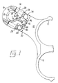
- the illustrative support is for an operative member, namely a funnel, of a glassware forming machine of the individual section type.
- the funnel (not shown) and another similar funnel are supported on an arm 10 of the support in locating rings 11.
- the funnels move between operative and out-of-the-way positions thereof along a path which has a vertical component and an arcuate component about a vertical axis 12.
- Movements of the funnel are brought about by a fluid-pressure operated moving mechanism (not shown) of conventional construction comprising a vertically-extending cylinder, a piston movable vertically in the cylinder upon the introduction of fluid under pressure into the cylinder, a piston rod 14 projecting from said piston along said vertical axis 12, and cam means acting on a second piston rod projecting from said piston in the opposite direction to said first piston rod 14 to cause the piston rod 14 to turn about the vertical axis 12 as it moves vertically.
- a fluid-pressure operated moving mechanism (not shown) of conventional construction comprising a vertically-extending cylinder, a piston movable vertically in the cylinder upon the introduction of fluid under pressure into the cylinder, a piston rod 14 projecting from said piston along said vertical axis 12, and cam means acting on a second piston rod projecting from said piston in the opposite direction to said first piston rod 14 to cause the piston rod 14 to turn about the vertical axis 12 as it moves vertically.
- the illustrative support comprises a first portion 16 in the form of a tubular rod telescopically-received over the piston rod 14.
- the illustrative support also comprises clamping means operable to clamp the tubular rod 16 to the piston rod 14 at a predetermined height.
- Said clamping means comprises two cooperating clamp members 18 and 20.
- the clamp member 18 is generally u-shaped and has an arcuate surface 22 which is received in a slot 24 through said tubular rod 16 so that the clamp member 18 engages the piston rod 14.
- the other clamp member 20 is arranged in opposed relationship to the clamp member 18 on the opposite side of the piston rod 14 and is located in a groove 26 formed in the tubular rod 16.
- Two clamping screws 28 pass through the clamp member 20 and are threadedly received in the clamp member 18 on opposite sides of the piston rod 14. Tightening the clamping screws 28 forces the clamp member 20 against the tubular rod 16 within the groove 26 and the clamp member 18 against the piston rod 14 within the slot 24 so that the tubular rod 16 is firmly fixed to the piston rod 14 at the predetermined height.
- the illustrative support also comprises a second portion 30 which is movable vertically relative to the first portion formed by the tubular rod 16.
- the second portion 30 is formed as a flange projecting horizontally from a cylinder 32 to be described further below.
- the arm 10 is mountable on the flange 30 of the support by means of two fixing screws 34 so that the funnels are mounted on an arm which is detachably mounted on the flange 30. Furthermore, vertical movement of the flange 30 relative to the tubular rod 16 causes the funnels to move vertically relative to the piston rod 14.
- the illustrative support also comprises moving means operable to move the second portion of the support provided by the flange 30 vertically relative to the first portion provided by the tubular rod 16.
- the moving means comprises a piston 36 formed externally on the tubular rod 16 and the aforementioned cylinder 32 which as aforementioned is secured to said second portion of the support formed by the flange 30.
- the piston 36 is received in the cylinder 32 so that a fluid-pressure operated piston and cylinder assembly is formed and introduction of fluid under pressure into the cylinder 32 through an upper port 38 or a lower port 40 thereof causes the flange 30 to move vertically downwardly or upwardly relative to the tubular portion 16 so that the funnels move vertically relative to the piston rod 14.
- the stroke of the piston and cylinder assembly 32,36 can be used to increase the vertical component of the path of movement of the funnels supported by the arm 10.
- the illustrative support also comprises locking means operative to prevent said first portion of the support formed by the tubular rod 16 from turning about a vertical axis 12 relative to said clamping means 18,20.
- Said locking means is provided by a locking screw 42 threadedly received in a bore in the clamping member 20. Locking screw 42 enters a bore 44 in the tubular rod 16 to prevent the clamp member 20 from turning relative to the tubular rod 16.
- the support also comprises key means operative to prevent said second portion of the support provided by the flange 30 from turning about the vertical axis 12 relative to said clamping means 18,20.
- Said key means is provided by a key member 46 mounted on the locking screw 42 and projecting downwardly therefrom.
- the key member 46 enters a vertical slot 48 in a flange 50 projecting horizontally from the cylinder 32.
- a flange 50 projecting horizontally from the cylinder 32.
Landscapes
- Engineering & Computer Science (AREA)
- Chemical & Material Sciences (AREA)
- Manufacturing & Machinery (AREA)
- Materials Engineering (AREA)
- Organic Chemistry (AREA)
- Manipulator (AREA)
- Jigs For Machine Tools (AREA)
- Manufacture Of Switches (AREA)
- Microscoopes, Condenser (AREA)
- Re-Forming, After-Treatment, Cutting And Transporting Of Glass Products (AREA)
Claims (7)
- Support pour un élément travaillant d'une machine à mouler le verre du type à sections individuelles, l'élément se déplaçant, au cours d'un cycle du fonctionnement de la machine, entre une position de travail et une position effacée, en suivant un trajet qui comprend une composante verticale et une composante incurvée en arc autour d'un axe vertical (12), le mouvement de l'élément étant provoqué par un mécanisme moteur actionné par une pression de fluide qui comprend un cylindre s'étendant verticalement, un piston qui se déplace verticalement dans le cylindre lorsqu'on introduit un fluide sous pression dans le cylindre, une tige de piston (14) qui fait saillie sur ce piston, le long de cet axe vertical, et des moyens du type came qui agissent sur une deuxième tige de piston qui fait saillie sur ce piston en sens inverse de cette première tige de piston, pour faire tourner la tige de piston autour de l'axe vertical lorsque cette tige se déplace verticalement, caractérisé en ce que le support comprend une première partie (16), une deuxième partie (30) qui peut se déplacer verticalement par rapport à la première partie, des moyens de serrage (18, 20, 28) qui peuvent être mis en action pour serrer la première partie sur la tige de piston (14) du mécanisme moteur à une hauteur prédéterminée, et des moyens moteurs (32, 36) pouvant être mis en action pour déplacer la deuxième partie verticalement par rapport à la première partie, l'élément travaillant pouvant être monté sur la deuxième partie du support.
- Support selon la revendication 1, caractérisé en ce que cette première partie (16) du support comprend une tige tubulaire montée télescopiquement sur la tige de piston (14).
- Support selon la revendication 2, caractérisé en ce que ces moyens de serrage comprennent deux éléments de collier (18, 20) coopérant entre eux, dont l'un (18) est logé dans une fente (24) pratiquée à travers cette tige tubulaire, de sorte que l'élément de collier (18) attaque la tige de piston (14) et que l'autre élément de collier (20) attaque la tige tubulaire (16).
- Support selon une quelconque des revendications 2 et 3, caractérisé en ce que ces moyens moteurs comprennent un piston (36) formé extérieurement sur la tige tubulaire (16), et un cylindre (32) fixé à cette deuxième partie (30) du support, le piston étant logé dans le cylindre de manière à former un ensemble piston et cylindre actionné par une pression de fluide et de manière que l'introduction de fluide sous pression dans le cylindre amène la deuxième partie du support à se déplacer verticalement par rapport à sa première partie (16).
- Support selon une quelconque des revendications 1 à 4, caractérisé en ce que ce support comprend aussi des moyens de verrouillage (42) capables d'empêcher cette première partie (16) du support de tourner autour d'un axe vertical par rapport à ces moyens de serrage (18, 20).
- Support selon une quelconque des revendications 1 à 5, caractérisé en ce que ce support comprend aussi des moyens du type clavette (46) capables d'empêcher cette partie (30) du support de tourner autour d'un axe vertical par rapport à ces moyens de serrage (18, 20).
- Support selon une quelconque des revendications 1 à 6, caractérisé en ce que l'élément travaillant est monté sur un bras (10) qui est monté de façon démontable sur cette deuxième partie (30) du support.
Applications Claiming Priority (2)
| Application Number | Priority Date | Filing Date | Title |
|---|---|---|---|
| GB8612712 | 1986-05-23 | ||
| GB868612712A GB8612712D0 (en) | 1986-05-23 | 1986-05-23 | Glassware forming machine |
Publications (3)
| Publication Number | Publication Date |
|---|---|
| EP0246776A2 EP0246776A2 (fr) | 1987-11-25 |
| EP0246776A3 EP0246776A3 (en) | 1989-09-06 |
| EP0246776B1 true EP0246776B1 (fr) | 1991-08-21 |
Family
ID=10598413
Family Applications (1)
| Application Number | Title | Priority Date | Filing Date |
|---|---|---|---|
| EP87303934A Expired EP0246776B1 (fr) | 1986-05-23 | 1987-05-01 | Support pour un membre opératif d'une machine de formage d'objets en verre |
Country Status (5)
| Country | Link |
|---|---|
| US (1) | US4764197A (fr) |
| EP (1) | EP0246776B1 (fr) |
| JP (1) | JPS62292628A (fr) |
| DE (1) | DE3772258D1 (fr) |
| GB (1) | GB8612712D0 (fr) |
Family Cites Families (6)
| Publication number | Priority date | Publication date | Assignee | Title |
|---|---|---|---|---|
| US1911119A (en) * | 1928-05-04 | 1933-05-23 | Hartford Empire Co | Glassware forming machine |
| US3477841A (en) * | 1966-07-19 | 1969-11-11 | Anchor Hocking Corp | Mold support for glassware forming machine |
| US3472642A (en) * | 1966-09-26 | 1969-10-14 | Owens Illinois Inc | Glass molding apparatus |
| US4120683A (en) * | 1977-08-01 | 1978-10-17 | Owens-Illinois, Inc. | Funnel arm operating mechanism |
| GB2093825B (en) * | 1981-02-27 | 1984-09-19 | Emhart Uk Ltd | Blowhead supporting and moving mechanism of a glassware forming machine |
| GB2166433B (en) * | 1984-10-27 | 1988-03-16 | Emhart Ind | Moving means for use in a glassware manufacturing machine |
-
1986
- 1986-05-23 GB GB868612712A patent/GB8612712D0/en active Pending
-
1987
- 1987-05-01 EP EP87303934A patent/EP0246776B1/fr not_active Expired
- 1987-05-01 DE DE8787303934T patent/DE3772258D1/de not_active Expired - Fee Related
- 1987-05-05 US US07/047,074 patent/US4764197A/en not_active Expired - Fee Related
- 1987-05-22 JP JP62125640A patent/JPS62292628A/ja active Pending
Also Published As
| Publication number | Publication date |
|---|---|
| US4764197A (en) | 1988-08-16 |
| EP0246776A3 (en) | 1989-09-06 |
| JPS62292628A (ja) | 1987-12-19 |
| GB8612712D0 (en) | 1986-07-02 |
| DE3772258D1 (de) | 1991-09-26 |
| EP0246776A2 (fr) | 1987-11-25 |
Similar Documents
| Publication | Publication Date | Title |
|---|---|---|
| US4272273A (en) | Plunger mechanism for glassware forming machine | |
| AU547419B2 (en) | A method of monitoring the closing action of a mould | |
| US3607206A (en) | Parison forming unit for glassware forming machine | |
| EP0195599B1 (fr) | Mécanisme d'ouverture et de fermeture de moules pour une machine de fabrication d'objets en verre | |
| WO1982002877A1 (fr) | Mecanisme d'ouverture et de fermeture de moule | |
| EP0210748B1 (fr) | Mécanisme de mouvement pour utilisation dans une machine de fabrication d'objets en verre du type à sections individuelles | |
| US4466821A (en) | Baffle moving and alignment means for the four gob glass forming machine | |
| CN1263057A (zh) | 玻璃容器自动取出机构 | |
| EP0694505A2 (fr) | Procédé et appareil pour la fabrication de verre creux à col large | |
| EP0246776B1 (fr) | Support pour un membre opératif d'une machine de formage d'objets en verre | |
| US4261724A (en) | Triple gob blowhead or baffle construction | |
| US4652291A (en) | Parison transferring mechanism | |
| US5587000A (en) | Takeout mechanism in glassware forming machine | |
| US4276076A (en) | Transfer means of glassware forming machines | |
| EP0216597B1 (fr) | Moyen de support pour un fond ébaucheur d'une machine de fabrication d'objets en verre | |
| EP0426313B1 (fr) | Moyens de mouvement utilisés dans une machine de formage de verre | |
| US3910419A (en) | Drive for movable elements such as rams and tongs in a machine for making bottles and similar containers from plasticizable material | |
| US5928400A (en) | Mounting Structure for a baffle or the like in a glassware manufacturing machine | |
| US4986844A (en) | Glassware forming machine of the individual section type | |
| US4579575A (en) | Blow head supporting and moving mechanism of a glassware forming machine | |
| US3561941A (en) | Triple gob settle blowhead and baffle construction | |
| US6085552A (en) | Aligning fixture for mold opening and closing mechanism | |
| US2862402A (en) | Turret and stop mechanism therefor | |
| US4244726A (en) | Apparatus for manufacturing glass bottles | |
| US4526604A (en) | Mould arrangement for a cyclicly-operating glassware container manufacturing machine with temperature sensing means |
Legal Events
| Date | Code | Title | Description |
|---|---|---|---|
| PUAI | Public reference made under article 153(3) epc to a published international application that has entered the european phase |
Free format text: ORIGINAL CODE: 0009012 |
|
| AK | Designated contracting states |
Kind code of ref document: A2 Designated state(s): DE FR GB IT |
|
| PUAL | Search report despatched |
Free format text: ORIGINAL CODE: 0009013 |
|
| AK | Designated contracting states |
Kind code of ref document: A3 Designated state(s): DE FR GB IT |
|
| 17P | Request for examination filed |
Effective date: 19900111 |
|
| RAP1 | Party data changed (applicant data changed or rights of an application transferred) |
Owner name: EMHART INDUSTRIES, INC. |
|
| RAP1 | Party data changed (applicant data changed or rights of an application transferred) |
Owner name: EMHART INDUSTRIES, INC. |
|
| 17Q | First examination report despatched |
Effective date: 19901015 |
|
| GRAA | (expected) grant |
Free format text: ORIGINAL CODE: 0009210 |
|
| AK | Designated contracting states |
Kind code of ref document: B1 Designated state(s): DE FR GB IT |
|
| REF | Corresponds to: |
Ref document number: 3772258 Country of ref document: DE Date of ref document: 19910926 |
|
| ET | Fr: translation filed | ||
| RAP2 | Party data changed (patent owner data changed or rights of a patent transferred) |
Owner name: EMHART GLASS MACHINERY INC., |
|
| ITF | It: translation for a ep patent filed | ||
| RAP2 | Party data changed (patent owner data changed or rights of a patent transferred) |
Owner name: EMHART GLASS MACHINERY INVESTMENTS INC. |
|
| PLBE | No opposition filed within time limit |
Free format text: ORIGINAL CODE: 0009261 |
|
| STAA | Information on the status of an ep patent application or granted ep patent |
Free format text: STATUS: NO OPPOSITION FILED WITHIN TIME LIMIT |
|
| 26N | No opposition filed | ||
| REG | Reference to a national code |
Ref country code: GB Ref legal event code: 732 |
|
| PGFP | Annual fee paid to national office [announced via postgrant information from national office to epo] |
Ref country code: FR Payment date: 19940413 Year of fee payment: 8 |
|
| PGFP | Annual fee paid to national office [announced via postgrant information from national office to epo] |
Ref country code: DE Payment date: 19940414 Year of fee payment: 8 |
|
| PGFP | Annual fee paid to national office [announced via postgrant information from national office to epo] |
Ref country code: GB Payment date: 19950418 Year of fee payment: 9 |
|
| PG25 | Lapsed in a contracting state [announced via postgrant information from national office to epo] |
Ref country code: DE Effective date: 19960201 |
|
| PG25 | Lapsed in a contracting state [announced via postgrant information from national office to epo] |
Ref country code: FR Effective date: 19960229 |
|
| REG | Reference to a national code |
Ref country code: FR Ref legal event code: ST |
|
| REG | Reference to a national code |
Ref country code: FR Ref legal event code: ST |
|
| PG25 | Lapsed in a contracting state [announced via postgrant information from national office to epo] |
Ref country code: GB Effective date: 19960501 |
|
| GBPC | Gb: european patent ceased through non-payment of renewal fee |
Effective date: 19960501 |
|
| PG25 | Lapsed in a contracting state [announced via postgrant information from national office to epo] |
Ref country code: IT Free format text: LAPSE BECAUSE OF NON-PAYMENT OF DUE FEES;WARNING: LAPSES OF ITALIAN PATENTS WITH EFFECTIVE DATE BEFORE 2007 MAY HAVE OCCURRED AT ANY TIME BEFORE 2007. THE CORRECT EFFECTIVE DATE MAY BE DIFFERENT FROM THE ONE RECORDED. Effective date: 20050501 |