EP0246807A2 - Transmission automatique pour bicyclette à plusieurs vitesses - Google Patents
Transmission automatique pour bicyclette à plusieurs vitesses Download PDFInfo
- Publication number
- EP0246807A2 EP0246807A2 EP87304257A EP87304257A EP0246807A2 EP 0246807 A2 EP0246807 A2 EP 0246807A2 EP 87304257 A EP87304257 A EP 87304257A EP 87304257 A EP87304257 A EP 87304257A EP 0246807 A2 EP0246807 A2 EP 0246807A2
- Authority
- EP
- European Patent Office
- Prior art keywords
- chain
- wheel
- engaging
- annulus
- axis
- Prior art date
- Legal status (The legal status is an assumption and is not a legal conclusion. Google has not performed a legal analysis and makes no representation as to the accuracy of the status listed.)
- Withdrawn
Links
- 230000005540 biological transmission Effects 0.000 title claims abstract description 62
- 230000033001 locomotion Effects 0.000 claims description 56
- 230000008093 supporting effect Effects 0.000 claims description 8
- 230000001965 increasing effect Effects 0.000 claims description 7
- 230000003247 decreasing effect Effects 0.000 claims description 2
- 230000007246 mechanism Effects 0.000 description 20
- 230000007423 decrease Effects 0.000 description 5
- 230000000875 corresponding effect Effects 0.000 description 4
- 210000000078 claw Anatomy 0.000 description 2
- 239000000314 lubricant Substances 0.000 description 2
- WYTGDNHDOZPMIW-RCBQFDQVSA-N alstonine Natural products C1=CC2=C3C=CC=CC3=NC2=C2N1C[C@H]1[C@H](C)OC=C(C(=O)OC)[C@H]1C2 WYTGDNHDOZPMIW-RCBQFDQVSA-N 0.000 description 1
- 230000000712 assembly Effects 0.000 description 1
- 238000000429 assembly Methods 0.000 description 1
- 238000005266 casting Methods 0.000 description 1
- 238000002485 combustion reaction Methods 0.000 description 1
- 230000006835 compression Effects 0.000 description 1
- 238000007906 compression Methods 0.000 description 1
- 230000007547 defect Effects 0.000 description 1
- 230000000994 depressogenic effect Effects 0.000 description 1
- 238000006073 displacement reaction Methods 0.000 description 1
- 230000007613 environmental effect Effects 0.000 description 1
- 230000005484 gravity Effects 0.000 description 1
- 238000004519 manufacturing process Methods 0.000 description 1
- 230000003014 reinforcing effect Effects 0.000 description 1
- 230000002226 simultaneous effect Effects 0.000 description 1
- XLYOFNOQVPJJNP-UHFFFAOYSA-N water Substances O XLYOFNOQVPJJNP-UHFFFAOYSA-N 0.000 description 1
- 238000003466 welding Methods 0.000 description 1
- 230000036642 wellbeing Effects 0.000 description 1
Images


Classifications
-
- B—PERFORMING OPERATIONS; TRANSPORTING
- B62—LAND VEHICLES FOR TRAVELLING OTHERWISE THAN ON RAILS
- B62M—RIDER PROPULSION OF WHEELED VEHICLES OR SLEDGES; POWERED PROPULSION OF SLEDGES OR SINGLE-TRACK CYCLES; TRANSMISSIONS SPECIALLY ADAPTED FOR SUCH VEHICLES
- B62M9/00—Transmissions characterised by use of an endless chain, belt, or the like
- B62M9/04—Transmissions characterised by use of an endless chain, belt, or the like of changeable ratio
- B62M9/06—Transmissions characterised by use of an endless chain, belt, or the like of changeable ratio using a single chain, belt, or the like
- B62M9/10—Transmissions characterised by use of an endless chain, belt, or the like of changeable ratio using a single chain, belt, or the like involving different-sized wheels, e.g. rear sprocket chain wheels selectively engaged by the chain, belt, or the like
- B62M9/12—Transmissions characterised by use of an endless chain, belt, or the like of changeable ratio using a single chain, belt, or the like involving different-sized wheels, e.g. rear sprocket chain wheels selectively engaged by the chain, belt, or the like the chain, belt, or the like being laterally shiftable, e.g. using a rear derailleur
- B62M9/121—Rear derailleurs
- B62M9/123—Rear derailleurs changing gears automatically
Definitions
- the present invention relates to an automatic transmission for a chain-driven rotating wheel.
- the invention relates to a linked chain-driven wheel where the ratio of the linear speed of the chain to the angular speed of the wheel about the hub thereof is automatically and incrementally adjusted.
- the invention finds particular application in the provision of an automatic transmission for a bicycle and like pedal driven apparatus and to bicycle wheels and bicycles including such transmissions.
- the conventional transmission changing mechanism on 5- and 10-speed bicycles is the so-called "derailleur” mechanism.
- the "derailleur” utilises multiple side-by-side sprockets of different diameters and rider-controlled levers to shift the bicycle drive chain from one sprocket to another of greater or lesser diameter.
- the "derailleur” is subject to a number of well-known problems.
- a novice shifting the chain from sprocket-to-sprocket can cause the chain to "hang up".
- the requirement to operate one or more levers while shifting may divert the attention of the bicyclist from his path of travel, and the occasional bicyclist may not readily develop the "feel" necessary to make a smooth shift between adjacent sprockets.
- Hayot U. S. Patent 2,584,447, discloses a variable-speed chain driving device comprising a hub mounted on the pedal shaft of a bicycle, the hub having mounted thereon flexible arms which carry at their extremities sprocket rollers which drive the chain of the bicycle.
- the flexible arms tend to wrap around the hub to decrease the effective diameter of the drive sprocket defined by the sprockets mounted on the arms, thereby reducing the transmission ratio to a fixed diameter sprocket driving the rear wheel.
- the transmission ratio is varied continuously and automatically in response to varying rear wheel resistance.
- U. S. Patent 3,837,2344 discloses a bicycle with a manually-operated stepless transmission wherein the rider can manually change the depth of groove between a pair of V sheaves, which define a V-belt pulley, the V-belt transmitting force to the rear wheel of the bicycle.
- Each of these teeth is carried by a carrier, in which the tooth is slidable. If the tooth is contacted by the bicycle chain on its rearward surface, the tooth will engage the chain and transmit drive pressure. However, if the tooth is contacted by the chain on its forward or upper surface, the tooth will be depressed into the carrier for the tooth and allow the chain to slide over the tooth.
- Pipenhagan, Jr. U. S. Patent 3,969.948, discloses an automatically variable speed ratio transmission for a bicycle, comprising a pedal-operated drive sprocket of variable diameter formed from a plurality of small sprockets mounted on bell-crank arms. The diameter of the so- formed sprocket being variable with the resistance to pedaling.
- Leonard U. S. Patent 4,030,373, discloses a variable speed drive for a bicycle comprising a variable diameter drive mechanism formed by a mounting plate having a number of radial tracks therein, and a number of sheave elements are each movably mounted in the tracks. The rider can manually cause the elements to move in the tracks to vary the diameter of the sheave pulley formed by the elements.
- each pulley is a V-belt pulley formed of two halves, the spacing between the halves defining the diameter at which a V-belt of fixed width will ride in the pulley, The spacing of the pulley halves is manually adjusted by the rider.
- variable diameter pulley is formed of a fixed plate and a movable plate, each plate is provided with slots and belt engaging elements ride between the plates and engage respective pairs of slots. As the load on the drive belt varies, the plates rotate with respect to each other and cause radial movement of the belt engaging elements, thereby varying the diameter of the pulley.
- U. S. Patent 904,330 discloses a driven shaft having a hub mounted thereon.
- This hub comprises a number of fixed spokes.
- the spokes have U-shaped cross sections and in each fixed spoke there is slidably mounted a sliding spoke which is formed at its outer end as a sector of the periphery of a belt pulley. Springs are provided which tend to pull the sectors to maximum diameter.
- the sliding spoke carries a pin which is engaged by a fork. This fork is pivoted about a point and carries a weight at its end. The operation of the apparatus is such that if the speed of rotation of the shaft increases, the weights will tend to move outwards and thereby exert an inwardly directed pull on the sectors.
- U. S. Patent 3,935,751 discloses a centrifugal, stepless speed changing device comprising a plurality of claw blocks mounted pivotally on a rotating disc. The outer ends of the claw blocks defining the periphery of a drive wheel. As the speed of rotation of the disc increases, the claw blocks move outward to increase the diameter of the wheel. Likewise, when the speed of the rotation of the disc decreases, the claw blocks move inward to decrease the diameter of the wheel.
- variable pulleys are V-belt pulleys comprised of a pair of opposed cone discs or pulley halves which cooperate with a V-belt, the variation in diameter being achieved by adjusting the axial spacing of the pulley halves which allows the V-belt to ride higher or lower in the groove between the pulley halves.
- Representatives of such variable diameter V-belt pulleys are Tyler , U. S. Patent 2,321,438; Carrol , U. S. Patent 2,491,248 (disclosing a remote control linkage and idling mechanism); Ingold , U. S.
- Patent 2,751,790 (disclosing a mechanism for simultaneous, equal and opposed movement of the pulley halves to prevent lateral movement of the belt); Wrobbel , U. S. Patent 2,941,412 (a further mechanism for simultaneous, equal and opposed movement of the pulley halves); Aplin , U. S. Patent 3,064,486 (a still further mechanism to assure belt alignment by achieving simultaneous, equal and opposite movement of the pulley halves); Schaufler , U. S. Patent 3,115,045 (a still further mechanism to assure belt alignment with diameter variation) and Looker , U. S. Patent 3,269,201 (a mechanism designed to prevent intrusion of dirt into and to preclude loss of lubricant from the pulley).
- belt-type drives for bicycles have generally been found to be inefficient and troublesome.
- belt drives tend to slip over the pulley when heavily loaded as when starting up on a bicycle or when traveling over a steep grade in the terrain. This slippage tendency is exacerbated in wet road conditions where water acts as a lubricant between the belt and pulley. Additionally, road dirt tends to act as an abrasive and increases the wear of the belt.
- the presennt invention provides an automatic transmission for a bicycle or like-pedaled apparatus wherein the speed ratio between the driven wheel (angular speed of the wheel) and the pedaled drive sprocket (linear speed of the chain) is automatically and incrementally adjustable in response to the speed of rotation of the driven wheel.
- the transmission is automatic in the sense that no rider intervention is required for speed ratio changes, the speed ratio changing solely in relation to the speed of rotation of the driven wheel.
- the transmission is incrementally adjustable in the sense that between previously determined upper and lower speed ratios a finite number of predetermined incremental jumps between ratios can be provided.
- the present invention provides an automatic transmission for a bicycle or like-pedaled apparatus.
- This automatic transmission which is applicable to any linked chain driven wheel comprises a plurality of chain-engaging sprockets disposed coaxially with and spaced apart along the axis of rotation of the wheel.
- Each of the sprockets has a predetermined diameter different from the diameter of each of the other sprockets.
- a drive means drivingly connects the plurality of chain-engaging sprockets to the wheel.
- a chain guide which engages the linked chain is provided.
- This chain guide is axially movable relative to the plurality of chain-engaging sprockets so as to be individually alignable with each of the sprockets in a respective plane, substantially transverse to the axis of rotation of the wheel.
- the chain guide guides the linked chain into engagement with the sprocket with which it is aligned.
- a chain guide actuator automatically varies the axial position of the chain guide in response to the angular speed of the wheel.
- the chain guide is axially moved by the chain guide actuator to automatically guide the linked chain into engagement with a sprocket of a diameter in relation to the angular speed of the wheel.
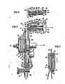
- Fig. 1 illustrates a bicycle utilizing the automatic transmission of the present invention.
- the bicycle comprises a supporting frame (indicated generally as 1), a front ground-engaging wheel 3 mounted on an axle 5 which is mounted on the supporting frame 1, a rear ground-engaging wheel 7 drivingly mounted on a first shaft (rear axle) 9 which is journally mounted on the supporting frame 1, a second shaft 11 journally mounted on the supporting frame 1 at substantially the fore and aft center of the frame between the front and rear wheels, foot-driven pedals 13, 15 mounted on opposite ends of the second shaft 11, a drive sprocket 17 fixedly mounted on the second shaft 11 for rotation therewith, the drive sprocket 17 is located adjacent to frame 1 and inwardly of pedal 13 on that end of second shaft 11, and an endless chain loop comprising a conventional bicycle chain 19 engaging the drive sprocket 17.
- the bicycle chain 19 also engages the automatic transmission according to the bicycle chain 19
- the automatic transmission 21 comprises a plurality of chain-engaging sprockets, 23, 25, 27, 29 and 31 (five being illustrated, but greater or lesser numbers being horriblyble depending on the number of gears desired and the desired trade-off with bulk and weight of the assembly).
- Each of the chain-engaging sprockets is disposed coaxially with and spaced apart along the axis of rotation 0-0 of the wheel 7.
- Each of the sprockets has a predetermined diameter and each diameter is different from the diameters of each of the other sprockets.
- Each of the sprockets is connected to a sprocket hub 33 which in turn is drivingly connected (as will be explained hereinafter) to the wheel hub 35 of wheel 7.
- a chain guide 37 engages the bicycle chain 19 (indicated by dot-dash lines in Figs. 4 and 5).
- the chain guide 37 is axially movable relative to the plurality of chain engaging sprockets, 23, 25, 27, 29 and 31, so as to be individually alignable with each of the sprockets in a respective plane, disposed substantially transverse to the axis 0-0, containing a respective sprocket (as best seen for sprocket 23 in Fig. 5 and for sprocket 31 in Fig. 4).
- a chain guide actuator (generally indicated at 39) is operatively connected to the chain guide 37 for varying the axial position of the chain guide in response to the angular speed of the wheel.
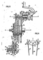
- the chain guide actuator 39 comprises a plurality of hollow cylinders 41, 43 and 45 (three being illustrated, since three points define a plane, but greater or lesser numbers being utilizable depending on the desired trade-off between stability, bulk and weight).
- Each hollow cylinder has an axis 0 ⁇ -0 ⁇ which is substantially parallel to the axis of rotation of the wheel 0-0.
- Each hollow cylinder (only cylinder 41 will be discussed in detail for ease of discussion) contains a piston 47 which is axially movable therein.
- the piston 47 is operably connected through a bell-arm crank 49 and a cable 51 to a centrifugal force generator which comprises at least one radially displaceable weight 53. As may best be seen in Fig.
- a radially displaceable weight 53, 55, and 57 is associated with each cylinder 41, 43 and 45, respectively, and operably connected thereto through cable 51, 59 and 61, respectively.
- the weight 53 is slidably received on wheel spoke 63.
- a detent 65 releasably locked on the spoke 63 by set screw 67 limits the inward movement of the weight 53 thereby maintaining cable 51 taut so as to prevent the cable from fouling in the bicycle chain 19 or with other moving parts.
- the cable 51 is received within recess 69 formed in weight 53 and fixedly held therein by set screw 71. While the weight 53 is an integral body, the mass of the weight 53 can be increased by attaching an additional weight 73 thereto as by a screw 75 or any other suitable connector.
- the weight may be formed in the general shape of a sector of a circle as illustrated for weight 77 in Fig. 8.
- the weight 77 has a pair of bores 79, 81 therethrough which are slidingly receivable of a pair of wheel spokes 83, 85.
- the bores must allow for the angle formed between the wheel spokes 83, 85 to insure that the spokes will slide within the bores.
- the weight 77 is operably connected to the bell-arm crank by cable 88.
- a detent is not necessary as the size of the bores and their relation to the spokes will determine the range of sliding movement of the weight 77.
- This embodiment is particularly advantageous in that the weight is shaped similarly to commercially available safety reflectors and may be painted a fluorescent color or fitted with a reflector for that purpose.
- the weight 77 may be formed in two halves which are joined together by screws 86, so that the weight 77 can be cast in two pieces. This allows channels to be formed in the castings which will form bores 79 and 81 upon assembly and thus reduce the cost of the weight. Moreover, an appropriate channel may be formed, in one of the halves, so as to capture the head 88a of cable 88 upon assembly.
- the hollow cylinder 41 is rigidly connected to support disc 87 which in turn is rigidly connected to wheel hub 35, whereby the support disc 87 will rotate about axis 0-0 as the wheel 7 rotates.
- the hollow cylinder 41 is preferably welded to the support disc 87 and may be provided with a reinforcing strut 89 to assure the strength and rigidity of the interconnection.
- the piston 47 is rigidly connected to a first annular support 91, which is coaxial with axis 0-0 and has an inner circumferential edge 91a slightly larger in diameter than said support disc 87 and an outer circumferential edge 91b, by way of a piston rod 93.
- the first annular support 91 may be rigidly connected to piston rod 93 by way of screw 95 or any other suitable means.
- a second annular support 97 which is coaxial with axis 0-0, is disposed about the first annular support 92.
- the inner circumferential edge 97a of the second annular support is slightly larger in diameter than the outer circumferential edge 91b of the first annular support.
- the outer circumferential edge 91b of the first annular support 91 has a groove 91c formed therein and a corresponding groove 97c is formed in the inner circumferential edge 97a of the second annular support 97.
- the second annular support 97 is freely rotatable about axis 0-0 relative to the first annular support 91, but moves as a unit with the first annular support 91 in the axial direction.
- a portion 101 of the outer periphery 97b of the second annular support 97 is widened so as to facilitate connection of the chain guide 37 thereto.
- the chain guide 37 comprises a shaft member 103 which has a first portion 103a of lesser diameter and a second portion 103b of greater diameter.
- the free end of the first portion 103a is received within an aperture 105 formed in the widened portion 101 of the second annular support 97.
- the free end of the first portion 103a is rigidly held within the aperture 105 by set screw 107.
- Axial movement of the Y-shaped member 107 is prevented by the abutment of the collar 109 against the widened portion 101 of the second annular support 97, and by the abutment of the one arm 107a of the Y-shaped member against the shoulder 113 formed between the first portion 103a and the second portion 103b of the shaft member 103.
- a helical spring 115 is wound about the second portion 103b of the shaft member 103.
- One end of the spring 115 is received in the aperture 117 formed in the one arm 107a of the Y-shaped member and the other end of the spring 115 engages a pin 119 carried by a disc 121 rigidly fixed to the free end of the second portion 103b of the shaft member 103 as by pin 123 (or any other suitable means).
- the other arm 107b of the Y-shaped member 107 has an aperture 125 therethrough which receives a pin 127 disposed parallel to axis 0-0.
- a chain-engaging sprocket 129 is rotatably mounted on the pin 127.
- the base 107c of the Y-shaped member 107 has an aperture (not shown) therethrough which receives a pin 131 disposed parallel to axis 0-0.
- a chain engaging sprocket 133 is rotatably mounted on the pin 131.
- the free ends of the pins 127 and 131 are each threaded (not shown) and screwed into a corresponding threaded aperture in a planar member 135 which is disposed in a plane parallel to the plane of the Y-shaped member 107. (Only a portion of the planar member 135 is illustrated in Figs.
- the two chain-engaging sprockets, 129 and 133 are held by the Y-shaped member 107 and the planar member 135 in a plane transverse to the axis 0-0.
- the bicycle chain 19 is looped about the chain-engaging sprockets 129 and 133 in a serpentine manner, as best seen in Fig. 3, and the chain is thus guided into engagement with the sprocket (23, 25, 27, 29 or 31) which lies in the plane defined by the chain-engaging sprockets 129, and 133.
- Axial movement of the chain guide 37 which is so formed will cause shifting of the bicycle chain from one of the sprockets 23, 25, 27, 29, 31 to another of these sprockets.
- the chain guide 37 acts to tension the bicycle chain thereby taking up the "slack" in the chain when the chain is shifted. Since the helical spring 115 yieldably urges the chain into a tensioned configuration, the chain guide may readily shift the chain from a sprocket, e.g., 23, 25 or 27, of lesser diameter to a sprocket, e.g., 29 or 31, of greater diameter.
- Axial movement of the chain guide 37 is brought about by axial movement of the second annular support 97, which in turn is brought about by axial movement of the first annular support 91.
- Axial movement of the first annular support 91 is effected by the chain guide actuator 39.
- the chain guide actuator 39 comprises three hollow cylinders 41, 43 and 45. Only cylinder 41 will be discussed in detail for ease of discussion, since the design and operation of all cylinders is identical.
- a piston 47 is contained within and axially movable relative to the hollow cylinder 41.
- the piston 47 is rigidly connected to piston rod 93 (and/or integrally formed therewith).
- the piston rod 93 is rigidly connected to the first annular support 91 by way of screw 95.
- the hollow cylinder 41 is rigidly connected to support disc 87.
- the end of the piston 47 opposte piston rod 93 is contacted by one arm 49a of a bell-arm crank which is pivotally connected to the hollow cylinder 41 by brackets 139 and 141 and pivot pin 143.
- Bushings-145 and 147 hold arm 49a in alignment with a diametric slit 149 formed in one end of the hollow cylinder 41.
- a biasing spring 151 contacts a washer member 153 which is rigidly fixed to the piston 47 and yieldably urges the piston 47 into engagement with a cam surface 49b formed on the arm 49a of bell-arm crank 49.
- the other arm 49c of the bell-arm crank 49 is connected to cable 51 which in turn is connecteed to radially movable weight 53.
- the piston rod 93 is formed with alternating portions of lesser diameter 93a and greater diameter 93b.
- An L-shaped lever arm 155 is pivotally mounted on cylinder 41 by a pivot pin 157 extending between brackets 139 and 141, said pivot pin 157 passing through the free end of long leg 155a of the L-shaped lever.
- the free end of the short leg 155b of the L-shaped lever engages the piston rod 93 in portions of lesser diameter 93a between adjacent portions of greater diameter 93b.
- the free end of the short leg 155b passes through a slot 159 in the hollow cylinder 41 and is yieldably urged into engagement with the piston rod 93 by biasing spring 161.
- biasing spring 161 is fixedly wound about pin 163 (supported between brackets 139 and 141) and the other end 161b is received within a groove 165 formed in the edge of lever arm 155. Since the free end of the short leg 155b of the lever 155 engages the portions 93a of lesser diameter of the piston rod, a stop mechanism is formed which will hold the piston rod in discrete positions, e.g., "low” gear as shown in Fig. 4 and "high” gear as shown in Fig. 5. As will be appreciated, the portions 93a of lesser diameter are positioned and spaced so as to correspond with the positioning of the chain guide 37 in alignment with the sprockets 23, 25, 27,29 and 31.
- the free end of the short leg 155b is provided with sloped surfaces 155c which correspond to sloped surfaces 93c formed on the portions 93b of greater diameter.
- the sprocket hub 33 In order to provide motive power to the rear wheel 7 of the bicycle, the sprocket hub 33 must be drivingly connected to the wheel hub 35 which is attached to the wheel 7 by spokes 83 which in turn are connected to flange 35a formed on the wheel hub 35. In its simplest and preferred form, sprocket hub 33 and wheel hub 35 are rigidly connected to one another. However, such an arrangement requires continuous pedal movement when the bike is in motion. In order to allow "coasting" (movement of the bicycle without pedal motion as when going down-hill with gravity providing the motive force), a conventional "free-wheel” mechanism can be provided in the connection between shaft 11 and drive sprocket 17.
- the conventional "free-wheel” mechanism can be provided as the driving connection between the sprocket hub 33 and the wheel hub 35.
- a gear change shifting of the chain from one of the sprockets to another
- the bicyclist is advised to periodically pedal, even during "coasting", so as to avoid untoward pressure being applied to the chain.
- the embodiment utilizes 5 sprockets of decreasing diameter to afford a 5-speed transmission.
- fewer or more sprockets can be utilized to provide fewer or more gears, e.g., 3 sprockets for a 3-speed transmission or 7 sprockets for a 7-speed transmission.
- the primary limitation on the number of gears (sprockets) is the available path of radial movement for the radially movable weights.
- the outward movement of the weights as transmitted through the cable 51 and bell- arm crank 49, determines the axial movement of the chain guide and thus, the number of sprockets which can be mounted on the sprocket hub 33.
- the present shifting mechanism is designed to maintain a constant pedaling speed on the part of the cyclist, e.g., 45-60 rpm, under all driving conditions, as has been found desirable in conventional transmissions.
- a drive sprocket 17 with 40 chain-engaging teeth and the utilization of five driven sprockets 23, 25, 27, 29 and 31 with 14, 17, 20, 24 and 28 chain-engaging teeth, respectively has been found advantageous.
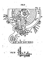
- a support is utilized to carry some of the load on the chain guide and thus reduce torsion forces on the first annular support and hence the piston assemblies.
- the second annular support is eliminated and a grooved wheel rides on the outer circumferential edge of the first annular support thereby eliminating the expense of fabricating and assembling a ball bearing race.
- Fig. 9 is a partial front view of the preferred embodiment of the present invention wherein the first annular support 91 has an axis corresponding to the rear axle 9, an inner circumferential edge 91a and an outer circumferential edge 91b.
- the first annular support 91 is disposed in a plane parallel to the plane of the chain guide 37.
- the first annular support is connected to the chain guide actuator (not shown) by screws 95 so as to be axially movable relative to the chain-engaging sprockets (23, 25, 27, 29, 31).
- a second annular support 97 also has an axis corresponding to the rear axle 9 and has an inner circumferential edge 97a and an outer circumferential edge 97b.
- the first annular support 91 and the second annular support are coaxially disposed in the same plane with the inner edge 97a of the second annular support 97 in sliding contact with the outer edge 91b of the first annular support 91.
- a widened portion 101 of the second annular support 97 has an elongated slot 171 formed therein.
- the first annular support 91 and the second annular support 97 are connected to each other by a ball bearing race formed by a groove 91c in the outer circumferential edge 91b of the first annular support 91 and a groove 97c in the inner circumferential edge 97a of the second annular support 97.
- the chain guide 37 is connected to and supported from the axle 9 by a connector (generally indicated at 173) which allows axial movement of the chain guide 37 relative to the sprockets (23, 25, 27, 29 and 31).
- the connector 173 comprises a first support member 175 which has, at one end, a hook portion 177 receivable of the axle 9 and the hook portion may be connected to the axle 9 by hex nut 179.
- a first pin 181 is rigidly connected to the other end of the support member 175 and extends therefrom in a direction away from the wheel (out of the plane of the paper toward the viewer in Fig. 9) and parallel to the axis of rotation of the wheel (parallel to axle 9).
- a second pin 183 is rigidly connected to the chain guide 37 and extends therefrom in a direction away from the wheel and parallel to the axis of rotation of the wheel.
- a first end member 185 is pivotally connected to the first pin 181 for pivotal motion in a plane substantially perpendicular to the axis of rotation of the wheel.
- a second end member 187 is pivotally connected to the second pin 183 for pivotal motion in a plane substantially perpendicular to the axis of rotation of the wheel.
- a pair of parallel link members 189, 191 are independently pivotally connected to the first end member 185 at pivots 193 and 195, respectively, and to the second end member 187 at pivots 197 and 199, respectively.
- Each of the pivots 193, 195, 197 and 199 allows pivotal motion in a plane substantially parallel to the axis of rotation of the wheel, i.e. about an axis transverse to the axis of rotation of the wheel.
- the link members 189, 191 are of equal length and the pivots 193, 195 and 197, 199 are equally spaced apart.
- a first spring 201 connected between said first support member 175 and said first end member 185 yieldably resists pivotal motion of said first end member 185 about said first pin 181.
- a second spring 203 connected between said chain guide 37 and said second end member 187 yieldably resists relative pivotal motion of said second end member 187 and said chain guide 37 about the second pin 183 and tensions the drive chain.
- the above-described linkage holds the first pin 181 and the second pin 183 parallel to one another during axial movement of the chain guide 37 relative to the plurality of chain-engaging sprockets (23, 25, 27, 29, 31).
- the chain guide 37 is connected to the second annular support 97, for axial movement therewith, through the connector 173 by a third pin 205, extending parallel to the axis of rotation of the wheel, which is received within bearing 207 and rigidly, detachably held therein by set screws 209.
- the bearing 207 is rigidly connected to the second end member 187 as by welding (illustrated at 211).
- the third pin 205 has a pair of flanges 213, 215 disposed substantially perpendicular thereto and rigidly attached thereto in spaced apart relation proximate the free end of the pin. One of the flanges 213, 215 is disposed on each side of slot 171 which receives the third pin 205 therein.
- the flanges 213, 215 retain pin 205 within the slot 171 so that the pin 205 can slide therein but it is prevented from moving in a direction parallel to the axis of rotation of the wheel.
- pins 181 and 183 are held in parallel and the center-to-center distance of these pins will vary with the axial movement of the chain guide 37, slot 171 must be provided to compensate for the change in center-to-center distance.
- a pivot arm 217 is pivotally connected to the chain guide 37, as by a pivot pin (not shown) extending parallel to the axis of rotation of the wheel.
- the pivot arm 217 is disposed substantially transverse to the axis of rotation of the wheel for pivotal motion in a plane substantially transverse to the axis of rotation of the wheel.
- a grooved wheel 219 having a groove 221 receivingly engageable of the outer circumferential edge 91b of annular support 91 is rotatably mounted, as by pin 223, on the free end of pivot arm 217.
- a biasing means such as a spring (not shown), is connected to the pivot arm 217 and the chain guide 37 to yieldably apply a force to the pivot arm 217 causing the pivot arm 217 to pivot and press the groove 221 of the grooved wheel 219 into engagement with the outer circumferential edge 91b of the annular support 91, so that the chain guide 37 will move as a unit with the annular support 91 upon axial movement of the annular support 91.
Landscapes
- Engineering & Computer Science (AREA)
- Chemical & Material Sciences (AREA)
- Combustion & Propulsion (AREA)
- Transportation (AREA)
- Mechanical Engineering (AREA)
- Transmissions By Endless Flexible Members (AREA)
- Transmission Devices (AREA)
- Control Of Transmission Device (AREA)
Applications Claiming Priority (2)
| Application Number | Priority Date | Filing Date | Title |
|---|---|---|---|
| US865800 | 1986-05-22 | ||
| US06/865,800 US4701152A (en) | 1986-05-22 | 1986-05-22 | Automatic transmission for multi-speed bicycle |
Publications (2)
| Publication Number | Publication Date |
|---|---|
| EP0246807A2 true EP0246807A2 (fr) | 1987-11-25 |
| EP0246807A3 EP0246807A3 (fr) | 1989-01-25 |
Family
ID=25346259
Family Applications (1)
| Application Number | Title | Priority Date | Filing Date |
|---|---|---|---|
| EP87304257A Withdrawn EP0246807A3 (fr) | 1986-05-22 | 1987-05-13 | Transmission automatique pour bicyclette à plusieurs vitesses |
Country Status (4)
| Country | Link |
|---|---|
| US (1) | US4701152A (fr) |
| EP (1) | EP0246807A3 (fr) |
| JP (1) | JPS6322784A (fr) |
| CA (1) | CA1271053A (fr) |
Cited By (3)
| Publication number | Priority date | Publication date | Assignee | Title |
|---|---|---|---|---|
| DE19543704C2 (de) * | 1995-11-23 | 1998-11-05 | Johannes Dipl Ing Ehrhardt | Einrichtung zur automatischen Betätigung von Fahrrad-Mehrgangschaltungen |
| DE19802563C1 (de) * | 1998-01-23 | 1999-09-16 | Schmitt Robert | Automatische Kettenschaltung |
| CN102837797A (zh) * | 2011-06-22 | 2012-12-26 | 谭国强 | 自行车的转矩驱动的自动变速设备 |
Families Citing this family (26)
| Publication number | Priority date | Publication date | Assignee | Title |
|---|---|---|---|---|
| US4836046A (en) * | 1987-05-04 | 1989-06-06 | Chappel Gilmore H | Automatic bicycle transmission |
| US4800768A (en) * | 1987-05-07 | 1989-01-31 | 4N Developments Ltd. | Power transmission apparatus |
| US5129272A (en) * | 1989-12-22 | 1992-07-14 | Nutec Transmission Ltd. | Continuously variable transmission |
| US5099706A (en) * | 1989-12-22 | 1992-03-31 | Naja International Inc. | Variable speed transmission |
| US5295916A (en) * | 1991-12-12 | 1994-03-22 | Chattin Jessie R | Automatic transmission for multispeed bicycle |
| US5350339A (en) * | 1993-03-10 | 1994-09-27 | Carmichael George H | Derailleur pulley for use with bicycle derailleur systems |
| US5599244A (en) * | 1995-08-14 | 1997-02-04 | Ethington; Russell A. | Automatic transmission shifter for velocipedes |
| US5980412A (en) * | 1997-11-15 | 1999-11-09 | Smith; Frank D. | Cam follower automatic torque converter transmission |
| US6045470A (en) * | 1998-02-06 | 2000-04-04 | Trek Bicycle Corporation | Front derailleur with chainline controlling idler cog |
| US6402650B1 (en) | 2000-07-07 | 2002-06-11 | John Morgan | Mechanical torque enhancing assembly |
| US7047817B2 (en) * | 2004-02-17 | 2006-05-23 | Forza, Inc. | Load measurement apparatus and methods utilizing torque sensitive link for pedal powered devices |
| US20070213150A1 (en) * | 2006-02-03 | 2007-09-13 | Jesse Chattin | Automatic transmission for multi-speed bicycle |
| US8297636B2 (en) * | 2008-07-15 | 2012-10-30 | Tai-Her Yang | Manpower-driven device with bi-directional input and constant directional rotation output |
| US8328214B2 (en) * | 2008-07-15 | 2012-12-11 | Tai-Her Yang | Manpower-driven device with bi-directional input and constant directional rotation output |
| US9327792B2 (en) * | 2011-01-28 | 2016-05-03 | Paha Designs, Llc | Gear transmission and derailleur system |
| EP2668089A4 (fr) * | 2011-01-28 | 2015-12-09 | Paha Designs Llc | Transmission par engrenage et système de dérailleur |
| US10207772B2 (en) * | 2011-01-28 | 2019-02-19 | Paha Designs, Llc | Gear transmission and derailleur system |
| US9033833B2 (en) * | 2011-01-28 | 2015-05-19 | Paha Designs, Llc | Gear transmission and derailleur system |
| US8845467B2 (en) * | 2011-04-05 | 2014-09-30 | Chang Hui Lin | Multiple sprocket assembly for bicycle |
| US8870693B2 (en) * | 2012-05-21 | 2014-10-28 | Shimano, Inc. | Bicycle derailleur with rotation resistance and tactile feedback |
| US9725132B2 (en) * | 2014-03-26 | 2017-08-08 | Shimano Inc. | Bicycle crank assembly |
| AT516330B1 (de) * | 2014-09-01 | 2016-06-15 | Gregor Schuster | Ansteuerung eines Getriebes mit segmentierten Rädern mittels elektrischer Stellelemente |
| US10011325B2 (en) * | 2014-12-10 | 2018-07-03 | Yeti Cycling, Llc | Linear derailleur mechanism |
| ITUA201696738U1 (it) * | 2016-05-04 | 2017-11-04 | Campagnolo Srl | Dispositivo attuatore per un cambio di bicicletta e relativo cambio di bicicletta. |
| DE102016112384A1 (de) * | 2016-07-06 | 2018-01-11 | Vyro Components Gmbh | Mitrotierende Stellvorrichtung zum Wechsel eines Zugmittels zwischen Radsätzen |
| CN108343708B (zh) * | 2017-01-23 | 2024-11-05 | 超汇桂盟传动(苏州)有限公司 | 链条及其内链片 |
Family Cites Families (15)
| Publication number | Priority date | Publication date | Assignee | Title |
|---|---|---|---|---|
| FR1026598A (fr) * | 1950-10-26 | 1953-04-29 | Dérailleur automatique pour cycles | |
| FR1048895A (fr) * | 1951-10-26 | 1953-12-24 | Changement de vitesse automatique pour bicyclettes | |
| FR1203123A (fr) * | 1958-07-22 | 1960-01-15 | Perfectionnements aux dispositifs de changement de vitesse pour véhicules à entraînement par chaîne et pignons, en particulier pour bicyclettes | |
| US3303711A (en) * | 1964-11-02 | 1967-02-14 | Vm Corp | Speed change mechanism for belt driven devices |
| US3661021A (en) * | 1969-07-26 | 1972-05-09 | Masakazu Ohshita Shimano Ind C | Multiple free wheel for a bicycle |
| GB1338659A (en) * | 1971-06-29 | 1973-11-28 | Morse M | Bicycles having speed changing means |
| US3830521A (en) * | 1973-01-11 | 1974-08-20 | Mattel Inc | Automatic shifter accessory for bicycles |
| US4099737A (en) * | 1977-04-27 | 1978-07-11 | Dayco Corporation | Bicycle belt drive system |
| US4201094A (en) * | 1977-11-28 | 1980-05-06 | Rathmell Richard K | Automatic speed shift for bicycles and the like |
| US4277077A (en) * | 1978-07-05 | 1981-07-07 | Maeda Industries, Ltd. | Variable-speed bicycle |
| US4571219A (en) * | 1980-09-15 | 1986-02-18 | Daniel Corporation | Bicycle transmission |
| US4612004A (en) * | 1983-08-02 | 1986-09-16 | Shimano Industrial Company Limited | Rear derailleur for a bicycle |
| US4580997A (en) * | 1983-11-14 | 1986-04-08 | Bicycle Partnership #1 | Two speed sprocket shift assembly |
| US4598920A (en) * | 1984-08-06 | 1986-07-08 | Robert Dutil | Automatic transmission for a bicycle and the like-pedaled apparatus |
| US4599079A (en) * | 1985-03-04 | 1986-07-08 | Chappell Gilmore H | Automatic derailleur shifter |
-
1986
- 1986-05-22 US US06/865,800 patent/US4701152A/en not_active Expired - Lifetime
-
1987
- 1987-05-13 EP EP87304257A patent/EP0246807A3/fr not_active Withdrawn
- 1987-05-15 CA CA000537317A patent/CA1271053A/fr not_active Expired
- 1987-05-22 JP JP62125628A patent/JPS6322784A/ja active Pending
Cited By (4)
| Publication number | Priority date | Publication date | Assignee | Title |
|---|---|---|---|---|
| DE19543704C2 (de) * | 1995-11-23 | 1998-11-05 | Johannes Dipl Ing Ehrhardt | Einrichtung zur automatischen Betätigung von Fahrrad-Mehrgangschaltungen |
| DE19802563C1 (de) * | 1998-01-23 | 1999-09-16 | Schmitt Robert | Automatische Kettenschaltung |
| CN102837797A (zh) * | 2011-06-22 | 2012-12-26 | 谭国强 | 自行车的转矩驱动的自动变速设备 |
| CN102837797B (zh) * | 2011-06-22 | 2016-12-07 | 谭国强 | 自行车的转矩驱动的自动变速设备 |
Also Published As
| Publication number | Publication date |
|---|---|
| CA1271053A (fr) | 1990-07-03 |
| JPS6322784A (ja) | 1988-01-30 |
| EP0246807A3 (fr) | 1989-01-25 |
| US4701152A (en) | 1987-10-20 |
Similar Documents
| Publication | Publication Date | Title |
|---|---|---|
| US4701152A (en) | Automatic transmission for multi-speed bicycle | |
| EP0615587B1 (fr) | Transmission automatique de bicyclette a plusieurs vitesses | |
| US4713042A (en) | Automatic transmission for a bicycle | |
| US4030373A (en) | Variable speed drive for a bicycle | |
| EP0213145B1 (fr) | Levier de deplacement automatique du derailleur | |
| US6173982B1 (en) | Self aligning crank assembly and method | |
| US20070213150A1 (en) | Automatic transmission for multi-speed bicycle | |
| US5163881A (en) | Automatic transmission for multi-speed bicycle | |
| US9855993B2 (en) | Variable diameter pulley assembly and continuously variable transmission using the same | |
| US4598920A (en) | Automatic transmission for a bicycle and the like-pedaled apparatus | |
| WO1984002562A1 (fr) | Transmission automatique variable de vitesse | |
| US6432009B1 (en) | Continuously variable transmission | |
| CN111094798A (zh) | 皮带轮和传动系统 | |
| US4946426A (en) | Self-positioning belt tensioner | |
| US5006094A (en) | Self-positioning belt tensioner | |
| US6045470A (en) | Front derailleur with chainline controlling idler cog | |
| US6068279A (en) | Two wheel drive bicycle | |
| US6007441A (en) | Automatic gear shifting mechanism for multi-speed manually powered vehicles | |
| US4909529A (en) | Bicycle with belt drive | |
| GB2169363A (en) | Alternative bicycle etc. wheel drive mechanisms | |
| GB2156015A (en) | Vehicle transmission | |
| US10094452B1 (en) | Continuously variable transmission for a bicycle | |
| CN87209772U (zh) | 自行车十六速全自动调径变速器 | |
| CN1114277A (zh) | 无级变速踏板式自行车传动装置 | |
| WO2003076260A1 (fr) | Systeme de transmission comprenant des engrenages a reglage radial |
Legal Events
| Date | Code | Title | Description |
|---|---|---|---|
| PUAI | Public reference made under article 153(3) epc to a published international application that has entered the european phase |
Free format text: ORIGINAL CODE: 0009012 |
|
| AK | Designated contracting states |
Kind code of ref document: A2 Designated state(s): AT BE CH DE ES FR GB GR IT LI LU NL SE |
|
| PUAL | Search report despatched |
Free format text: ORIGINAL CODE: 0009013 |
|
| AK | Designated contracting states |
Kind code of ref document: A3 Designated state(s): AT BE CH DE ES FR GB GR IT LI LU NL SE |
|
| 17P | Request for examination filed |
Effective date: 19890601 |
|
| 17Q | First examination report despatched |
Effective date: 19900912 |
|
| STAA | Information on the status of an ep patent application or granted ep patent |
Free format text: STATUS: THE APPLICATION IS DEEMED TO BE WITHDRAWN |
|
| 18D | Application deemed to be withdrawn |
Effective date: 19910123 |