EP0246935A1 - Clavier pour appareil électrique - Google Patents
Clavier pour appareil électrique Download PDFInfo
- Publication number
- EP0246935A1 EP0246935A1 EP87400834A EP87400834A EP0246935A1 EP 0246935 A1 EP0246935 A1 EP 0246935A1 EP 87400834 A EP87400834 A EP 87400834A EP 87400834 A EP87400834 A EP 87400834A EP 0246935 A1 EP0246935 A1 EP 0246935A1
- Authority
- EP
- European Patent Office
- Prior art keywords
- detectors
- excitation
- keyboard
- locations
- modification
- Prior art date
- Legal status (The legal status is an assumption and is not a legal conclusion. Google has not performed a legal analysis and makes no representation as to the accuracy of the status listed.)
- Withdrawn
Links
Images
Classifications
-
- H—ELECTRICITY
- H03—ELECTRONIC CIRCUITRY
- H03K—PULSE TECHNIQUE
- H03K17/00—Electronic switching or gating, i.e. not by contact-making and –breaking
- H03K17/94—Electronic switching or gating, i.e. not by contact-making and –breaking characterised by the way in which the control signals are generated
- H03K17/941—Electronic switching or gating, i.e. not by contact-making and –breaking characterised by the way in which the control signals are generated using an optical detector
- H03K17/943—Electronic switching or gating, i.e. not by contact-making and –breaking characterised by the way in which the control signals are generated using an optical detector using a plurality of optical emitters or detectors, e.g. keyboard
-
- H—ELECTRICITY
- H03—ELECTRONIC CIRCUITRY
- H03K—PULSE TECHNIQUE
- H03K2217/00—Indexing scheme related to electronic switching or gating, i.e. not by contact-making or -breaking covered by H03K17/00
- H03K2217/94—Indexing scheme related to electronic switching or gating, i.e. not by contact-making or -breaking covered by H03K17/00 characterised by the way in which the control signal is generated
- H03K2217/941—Indexing scheme related to electronic switching or gating, i.e. not by contact-making or -breaking covered by H03K17/00 characterised by the way in which the control signal is generated using an optical detector
- H03K2217/94116—Indexing scheme related to electronic switching or gating, i.e. not by contact-making or -breaking covered by H03K17/00 characterised by the way in which the control signal is generated using an optical detector increasing reliability, fail-safe
Definitions
- the invention relates to a keyboard for an electrical appliance, of the type comprising several locations capable of responding to local excitation, by causing a corresponding modification in at least one electrical circuit, for example a change of state.
- Such keyboards are widely used in electronics and computers, for example on telephones, pocket calculators, computers, doormen of villas and buildings for example.
- electromechanical keyboards known as "with push buttons” have been known for a very long time, in which the locations mentioned above are keys and the excitation is a pressure exerted on them; most often, this pressure causes a change of state of the electrical circuit, namely an opening or a closing of the circuit according to the initial state of the latter, a switch being associated with each key and mechanically linked to it; these keyboards are subject to mechanical breakdowns due either to too rough handling, or to normal wear in the event of intensive use, and also to electrical breakdowns at the level of their contacts; in addition, they do not have a very high resistance to acts of vandalism, because the keys can be relatively easily jammed or torn off for example; also, because of the presence of movable parts accessible from the outside, these keyboards have poor climatic resistance, and a tightness which is difficult to ensure, particularly when they are intended to equip external devices to premises such as "doormen "villas or buildings; this results in a relatively short life, for devices that are often expensive and more and more numerous in our daily environment
- keyboards have always appeared, electromechanical, but with elastomer, and keyboards with relay with flexible blades, which are, like conventional keyboards, so-called “contacting” keyboards. ", because they require to operate, to exert a weak but real pressure, in a place playing the role of push. These keyboards are more reliable than the previous ones, but the large number of moving parts is still a source of breakdowns, however.
- keyboards are therefore much less prone to mechanical breakdowns, and have better resistance to vandalism, insofar as they have no moving parts accessible externally. However, they are still sensitive to climatic conditions and also to atmospheric disturbances which are reflected electromagnetically for example.
- the object of the present invention is to remedy these drawbacks and for this purpose concerns a keyboard for an electrical appliance, of the type comprising several locations arranged in a matrix and identified by a respective alphanumeric character, capable of responding to local excitation by causing a corresponding modification of the level of an electrical quantity , and at least one analysis detector placed opposite each location and connected to an electrical analysis circuit suitable for delivering an output signal constituted by said change in level of the electrical quantity during such an excitation of the corresponding location resulting in a modification of the illumination of said detector, keyboard characterized in that it includes locations not identified and also capable of responding to local excitation by causing a corresponding change in the level of the same electrical quantity as well as detectors which are arranged opposite these non-r locations and are connected to inputs of a reference circuit comprising at least one amplifier and the output of which is connected to each analysis circuit to supply them with a reference signal which is a function of the excitation of said unmarked locations, and in that all the detectors are light detectors made up of photosensitive semiconductor components such as
- the electrical circuit is controlled by detectors such as light detectors operating in response to a difference in light intensity level, it is possible to avoid any emergence of the functional part of the keyboard outside the plane of its support. This results in effective protection against vandalism and a significant reduction in the number of cases where it is necessary to carry out an expensive replacement of elements transmitting order or data; as the keyboard has locations not identified and also capable of responding to local excitation in the same way as alphanumeric locations, and reference detectors arranged as well as the analysis detectors and connected to a reference circuit to provide analysis circuits a reference signal, and as the detectors are embedded in the same base plate, the operation of the keyboard is independent of the conditions ambient and unintended disturbances.
- detectors such as light detectors operating in response to a difference in light intensity level
- the circuit associated with the light detector is capable of being traversed by a current whose intensity is variable between two values, one of which is practically zero.
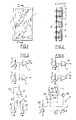
- the keyboard shown in the figures is a solid keyboard that does not contact the transmitter of orders or data by means of electrical pulses generated under optical control.
- This keyboard can receive innumerable applications, and being particularly well adapted to withstand bad weather, is capable of being advantageously used in devices for locking or unlocking building doors.
- its mechanical base is a rectangular metal plate 1, provided in one of its faces, with a housing itself rectangular in which is embedded, without protruding from the plane of the periphery of the metal plate, a plate protection 2, transparent or at least translucent, for light detectors 3,4 inserted into cavities 5 passing through the metal plate 1 right through.
- the light detectors here phototransistors, have their sensitive surface facing the protective plate, which is made of glass or plastic of a few millimeters
- the phototransistors are fourteen in number; twelve of them are analysis phototransistors 3 distributed in a matrix arrangement with four lines and three columns, and the additional detectors 4, for reference, are in alignment with the central column respectively above and above below the first and last lines, here at a distance from these lines equal to the spacing between two lines.
- All of the detectors 3,4 are arranged in the part of the base plate 1 which is opposite the protection plate 2, so that all of them can be excited by any incident light, whether it be light of daylight, or that of an external light, or even an auxiliary light emitted near the keyboard, with the possible exception of one of the detectors 3 masked by the user, for example by means of the end with one of his fingers.
- each analysis detector 3 In front of each analysis detector 3 is written a typographic sign, for example a number from 0 to 9 or a letter (alphanumeric character).
- the printed circuit board 6 carries the electronic processing of the signals emitted by the phototransistors 3,4.
- This electronics notably comprises on the one hand as many analysis circuits 7 as analysis detectors 3, and a reference circuit 8 corresponding to the two reference detectors 4 and intended to supply the analysis circuits with the reference level, any transition to a substantially different level and corresponding to a weaker light therefore constituting a useful signal.
- the reference circuit 8 can be envisaged in several forms, two of them being shown respectively in FIGS. 3 and 4.
- the two reference phototransistors 4 drive the same input of an operational amplifier 81; for this purpose, they are each supplied in common transmitter assembly by a continuous source, their collector being connected to the positive pole of the source by means of a resistor 82, and to the input of amplifier 81 by another resistance 83; the gain of the operational amplifier is regulated by a feedback resistor 84. It is therefore the sum of the output currents of the phototransistors 4 which attacks the amplifier (which comes to the same as the average of these currents).
- the output of amplifier 81 is connected to each of the analysis circuits 7.
- the two phototransistors 4 also in common emitter assembly (collector connected to the positive pole of the source by a resistor 82), each attack a different input of the operational amplifier 81;
- the feedback loop of each input of the amplifier 81 mounted in comparator comprises in series a resistor 84, and for the positive input, the emitter-low space of a transistor 85, and, for the negative input , the collector-base space of another transistor 86, the collector of the first transistor and the emitter of the second being connected to each other and connected to each of the analysis circuits 7. It follows that c is practically the signal coming from the least lit phototransistor 4 which serves as a reference for the analysis circuits 7.
- Each of the analysis circuits 7 comprises a phototransistor 3 in common emitter assembly (collector connected to a positive source by a resistor 71) whose collector is moreover connected to an input (negative) of an operational amplifier 72 mounted as a level comparator, the other input (positive) of which is connected to the reference circuit 8 in the manner described above to receive an electrical signal corresponding thereto of the overall brightness.
- the output of the analysis circuits 7 attacks the following stages in cascade as is conventional. In this way, the reference detectors 4 capture the ambient light or the light emitted by an auxiliary source associated with the keyboard, and take into account the light level of this light as a reference level.
Landscapes
- Input From Keyboards Or The Like (AREA)
- Electronic Switches (AREA)
- Push-Button Switches (AREA)
Applications Claiming Priority (2)
| Application Number | Priority Date | Filing Date | Title |
|---|---|---|---|
| FR8605699 | 1986-04-21 | ||
| FR8605699A FR2597682A1 (fr) | 1986-04-21 | 1986-04-21 | Clavier pour appareil electrique. |
Publications (1)
| Publication Number | Publication Date |
|---|---|
| EP0246935A1 true EP0246935A1 (fr) | 1987-11-25 |
Family
ID=9334434
Family Applications (1)
| Application Number | Title | Priority Date | Filing Date |
|---|---|---|---|
| EP87400834A Withdrawn EP0246935A1 (fr) | 1986-04-21 | 1987-04-13 | Clavier pour appareil électrique |
Country Status (7)
| Country | Link |
|---|---|
| EP (1) | EP0246935A1 (da) |
| JP (1) | JPS62258517A (da) |
| CA (1) | CA1260108A (da) |
| DK (1) | DK196087A (da) |
| FI (1) | FI871717A7 (da) |
| FR (1) | FR2597682A1 (da) |
| NO (1) | NO871628L (da) |
Cited By (2)
| Publication number | Priority date | Publication date | Assignee | Title |
|---|---|---|---|---|
| FR2674077A1 (fr) * | 1991-03-11 | 1992-09-18 | Voiturier Jean Pierre | Contracteur optique. |
| EP1703641A1 (de) * | 2005-03-16 | 2006-09-20 | Diehl AKO Stiftung & Co. KG | Optischer Berührungsschalter mit hoher Funktionssicherheit und Verfahren zum Betrieb desselben |
Families Citing this family (3)
| Publication number | Priority date | Publication date | Assignee | Title |
|---|---|---|---|---|
| US4937443A (en) * | 1989-07-28 | 1990-06-26 | Motorola, Inc. | Photoelectric ambient light switch with ambient light sensing means |
| DE19547300C1 (de) * | 1995-12-18 | 1997-03-06 | Siemens Ag | Betätigungsvorrichtung mit zumindest einem optoelektronischen Tastenelement |
| FR2936119B1 (fr) * | 2008-09-12 | 2010-11-05 | Schneider Electric Ind Sas | Dispositif de commande incluant un capteur photovoltaique |
Citations (3)
| Publication number | Priority date | Publication date | Assignee | Title |
|---|---|---|---|---|
| GB1238428A (da) * | 1969-05-02 | 1971-07-07 | ||
| US4329581A (en) * | 1980-06-04 | 1982-05-11 | General Electric Company | Ambient light sensor touch switch system and method |
| EP0163138A1 (en) * | 1984-05-21 | 1985-12-04 | Energy Conversion Devices, Inc. | Touch sensitive keyboard input device and method |
-
1986
- 1986-04-21 FR FR8605699A patent/FR2597682A1/fr not_active Withdrawn
-
1987
- 1987-04-13 EP EP87400834A patent/EP0246935A1/fr not_active Withdrawn
- 1987-04-15 NO NO871628A patent/NO871628L/no unknown
- 1987-04-15 DK DK196087A patent/DK196087A/da not_active Application Discontinuation
- 1987-04-16 FI FI871717A patent/FI871717A7/fi not_active Application Discontinuation
- 1987-04-16 CA CA000534967A patent/CA1260108A/fr not_active Expired
- 1987-04-21 JP JP62098484A patent/JPS62258517A/ja active Pending
Patent Citations (3)
| Publication number | Priority date | Publication date | Assignee | Title |
|---|---|---|---|---|
| GB1238428A (da) * | 1969-05-02 | 1971-07-07 | ||
| US4329581A (en) * | 1980-06-04 | 1982-05-11 | General Electric Company | Ambient light sensor touch switch system and method |
| EP0163138A1 (en) * | 1984-05-21 | 1985-12-04 | Energy Conversion Devices, Inc. | Touch sensitive keyboard input device and method |
Cited By (2)
| Publication number | Priority date | Publication date | Assignee | Title |
|---|---|---|---|---|
| FR2674077A1 (fr) * | 1991-03-11 | 1992-09-18 | Voiturier Jean Pierre | Contracteur optique. |
| EP1703641A1 (de) * | 2005-03-16 | 2006-09-20 | Diehl AKO Stiftung & Co. KG | Optischer Berührungsschalter mit hoher Funktionssicherheit und Verfahren zum Betrieb desselben |
Also Published As
| Publication number | Publication date |
|---|---|
| DK196087A (da) | 1987-10-22 |
| FI871717A0 (fi) | 1987-04-16 |
| DK196087D0 (da) | 1987-04-15 |
| NO871628D0 (no) | 1987-04-15 |
| CA1260108A (fr) | 1989-09-26 |
| FR2597682A1 (fr) | 1987-10-23 |
| NO871628L (no) | 1987-10-22 |
| JPS62258517A (ja) | 1987-11-11 |
| FI871717A7 (fi) | 1987-10-22 |
Similar Documents
| Publication | Publication Date | Title |
|---|---|---|
| FR2697935A1 (fr) | Terminal de communication compact et ergonomique muni de surfaces de détection de proximité. | |
| EP0062572B1 (fr) | Clavier capacitif à structure antiparasite | |
| FR2790567A1 (fr) | Clavier de touches permettant une lecture tactile d'informations provenant d'un calculateur electronique | |
| EP3035534B1 (fr) | Clavier a fiabilite amelioree | |
| CN104347300B (zh) | 发光键盘 | |
| EP0246935A1 (fr) | Clavier pour appareil électrique | |
| EP0375545A1 (fr) | Dispositif de protection d'une carte électronique et utilisation pour protéger un terminal de lecture de carte magnétique et/ou à microprocesseur | |
| CN1471688A (zh) | 便携式无线通信设备 | |
| EP0203923B1 (fr) | Procede pour scruter un clavier a touches capacitives et un clavier assorti de moyens pour scruter un clavier selon ce procede | |
| EP0817382B1 (fr) | Système de commutation entre des états de veille et de réveil d'une unité de traitement d'informations et d'un commutateur analogique | |
| US20250148886A1 (en) | Systems and methods for light-based tamper detection in point-of-sale devices | |
| CA2998625A1 (fr) | Clavier securise pour dispositif electronique de saisie de donnees | |
| EP3035002A1 (fr) | Codeur optique robuste | |
| GB2410004A (en) | Keypad | |
| EP0200636B1 (fr) | Dispositif électromécanique de manoeuvre commandé par code et comportant un dispositif d'alarme d'actionnement sous contrainte | |
| EP3251004B1 (fr) | Systeme interactif tactile et borne de commande | |
| US20260104761A1 (en) | Environmentally isolated keypad assembly with tactile feedback | |
| FR2733270A1 (fr) | Dispositif de commande electrique d'ouverture a code pour porte ou similaire | |
| EP0231717A1 (fr) | Dispositif de commande, de signalisation et de dialogue, en particulier pour sas asservis | |
| KR900009184Y1 (ko) | 광을 이용한 스위치용 버튼 | |
| FR2806176A3 (fr) | Clavier muni de molettes rotatives | |
| FR2736745A1 (fr) | Dispositif de commande a distance d'un systeme interactif | |
| FR2752971A1 (fr) | Dispositif authentifieur multi-lecteurs et lecteur magnetique associe | |
| FR2600368A1 (fr) | Dispositif de securite pour serrures de contact, lecteurs de clefs et mecanismes | |
| FR2985338A1 (fr) | Clavier securise |
Legal Events
| Date | Code | Title | Description |
|---|---|---|---|
| PUAI | Public reference made under article 153(3) epc to a published international application that has entered the european phase |
Free format text: ORIGINAL CODE: 0009012 |
|
| AK | Designated contracting states |
Kind code of ref document: A1 Designated state(s): AT BE CH DE ES GB GR IT LI LU NL SE |
|
| 17P | Request for examination filed |
Effective date: 19880128 |
|
| 17Q | First examination report despatched |
Effective date: 19890829 |
|
| STAA | Information on the status of an ep patent application or granted ep patent |
Free format text: STATUS: THE APPLICATION IS DEEMED TO BE WITHDRAWN |
|
| 18D | Application deemed to be withdrawn |
Effective date: 19920730 |
|
| RIN1 | Information on inventor provided before grant (corrected) |
Inventor name: MARMET, PATRICK |