EP0247000B1 - Transducteur pour environnements hostiles - Google Patents
Transducteur pour environnements hostiles Download PDFInfo
- Publication number
- EP0247000B1 EP0247000B1 EP87730055A EP87730055A EP0247000B1 EP 0247000 B1 EP0247000 B1 EP 0247000B1 EP 87730055 A EP87730055 A EP 87730055A EP 87730055 A EP87730055 A EP 87730055A EP 0247000 B1 EP0247000 B1 EP 0247000B1
- Authority
- EP
- European Patent Office
- Prior art keywords
- screen
- winding
- drive
- sense
- field
- Prior art date
- Legal status (The legal status is an assumption and is not a legal conclusion. Google has not performed a legal analysis and makes no representation as to the accuracy of the status listed.)
- Expired - Lifetime
Links
- 238000004804 winding Methods 0.000 claims description 161
- 230000004888 barrier function Effects 0.000 claims description 38
- 229910001220 stainless steel Inorganic materials 0.000 claims description 25
- 239000010935 stainless steel Substances 0.000 claims description 25
- 239000000463 material Substances 0.000 claims description 15
- 238000012216 screening Methods 0.000 claims description 13
- 238000006073 displacement reaction Methods 0.000 claims description 8
- 230000002093 peripheral effect Effects 0.000 claims description 8
- RYGMFSIKBFXOCR-UHFFFAOYSA-N Copper Chemical compound [Cu] RYGMFSIKBFXOCR-UHFFFAOYSA-N 0.000 claims description 6
- 229910052802 copper Inorganic materials 0.000 claims description 6
- 239000010949 copper Substances 0.000 claims description 6
- 239000004020 conductor Substances 0.000 claims description 5
- 230000005291 magnetic effect Effects 0.000 claims description 5
- 238000009826 distribution Methods 0.000 claims description 4
- 238000010276 construction Methods 0.000 description 14
- 238000013461 design Methods 0.000 description 13
- 230000004907 flux Effects 0.000 description 13
- 238000005259 measurement Methods 0.000 description 12
- 230000006870 function Effects 0.000 description 11
- 230000033001 locomotion Effects 0.000 description 11
- 230000000694 effects Effects 0.000 description 8
- 230000007704 transition Effects 0.000 description 8
- 230000008901 benefit Effects 0.000 description 7
- 230000035515 penetration Effects 0.000 description 7
- 239000007788 liquid Substances 0.000 description 6
- 238000010586 diagram Methods 0.000 description 5
- 239000012530 fluid Substances 0.000 description 5
- 238000000034 method Methods 0.000 description 5
- 230000008859 change Effects 0.000 description 4
- 230000007613 environmental effect Effects 0.000 description 4
- 238000012545 processing Methods 0.000 description 4
- 239000004411 aluminium Substances 0.000 description 3
- 229910052782 aluminium Inorganic materials 0.000 description 3
- XAGFODPZIPBFFR-UHFFFAOYSA-N aluminium Chemical compound [Al] XAGFODPZIPBFFR-UHFFFAOYSA-N 0.000 description 3
- 230000002349 favourable effect Effects 0.000 description 3
- 238000007493 shaping process Methods 0.000 description 3
- 239000007787 solid Substances 0.000 description 3
- 230000002277 temperature effect Effects 0.000 description 3
- 230000006978 adaptation Effects 0.000 description 2
- 238000004458 analytical method Methods 0.000 description 2
- 230000004323 axial length Effects 0.000 description 2
- 238000006243 chemical reaction Methods 0.000 description 2
- 230000004069 differentiation Effects 0.000 description 2
- 230000001939 inductive effect Effects 0.000 description 2
- 230000005405 multipole Effects 0.000 description 2
- 230000003287 optical effect Effects 0.000 description 2
- 230000004044 response Effects 0.000 description 2
- 238000000926 separation method Methods 0.000 description 2
- 230000001360 synchronised effect Effects 0.000 description 2
- 238000012546 transfer Methods 0.000 description 2
- BYHQTRFJOGIQAO-GOSISDBHSA-N 3-(4-bromophenyl)-8-[(2R)-2-hydroxypropyl]-1-[(3-methoxyphenyl)methyl]-1,3,8-triazaspiro[4.5]decan-2-one Chemical compound C[C@H](CN1CCC2(CC1)CN(C(=O)N2CC3=CC(=CC=C3)OC)C4=CC=C(C=C4)Br)O BYHQTRFJOGIQAO-GOSISDBHSA-N 0.000 description 1
- 230000001133 acceleration Effects 0.000 description 1
- 238000007630 basic procedure Methods 0.000 description 1
- 230000000903 blocking effect Effects 0.000 description 1
- 238000004364 calculation method Methods 0.000 description 1
- 238000001311 chemical methods and process Methods 0.000 description 1
- 230000000295 complement effect Effects 0.000 description 1
- 230000003750 conditioning effect Effects 0.000 description 1
- 230000008094 contradictory effect Effects 0.000 description 1
- 238000012937 correction Methods 0.000 description 1
- 238000005260 corrosion Methods 0.000 description 1
- 230000007797 corrosion Effects 0.000 description 1
- 230000008878 coupling Effects 0.000 description 1
- 238000010168 coupling process Methods 0.000 description 1
- 238000005859 coupling reaction Methods 0.000 description 1
- 238000013016 damping Methods 0.000 description 1
- 210000003298 dental enamel Anatomy 0.000 description 1
- 238000009795 derivation Methods 0.000 description 1
- 238000001514 detection method Methods 0.000 description 1
- 238000011161 development Methods 0.000 description 1
- 230000018109 developmental process Effects 0.000 description 1
- 238000009792 diffusion process Methods 0.000 description 1
- 230000003467 diminishing effect Effects 0.000 description 1
- 230000009977 dual effect Effects 0.000 description 1
- 230000005284 excitation Effects 0.000 description 1
- 230000005294 ferromagnetic effect Effects 0.000 description 1
- 239000003302 ferromagnetic material Substances 0.000 description 1
- -1 for example Substances 0.000 description 1
- 239000007789 gas Substances 0.000 description 1
- 230000036039 immunity Effects 0.000 description 1
- 230000006872 improvement Effects 0.000 description 1
- 238000003780 insertion Methods 0.000 description 1
- 230000037431 insertion Effects 0.000 description 1
- 230000010354 integration Effects 0.000 description 1
- 239000000696 magnetic material Substances 0.000 description 1
- 238000004519 manufacturing process Methods 0.000 description 1
- 238000002844 melting Methods 0.000 description 1
- 230000008018 melting Effects 0.000 description 1
- 229910052751 metal Inorganic materials 0.000 description 1
- 239000002184 metal Substances 0.000 description 1
- 239000000203 mixture Substances 0.000 description 1
- 238000012544 monitoring process Methods 0.000 description 1
- 230000009972 noncorrosive effect Effects 0.000 description 1
- 230000035699 permeability Effects 0.000 description 1
- 239000003208 petroleum Substances 0.000 description 1
- 229920003023 plastic Polymers 0.000 description 1
- 239000004033 plastic Substances 0.000 description 1
- 230000008569 process Effects 0.000 description 1
- 230000035945 sensitivity Effects 0.000 description 1
- 238000011282 treatment Methods 0.000 description 1
- 238000009827 uniform distribution Methods 0.000 description 1
- 239000000037 vitreous enamel Substances 0.000 description 1
Images


Classifications
-
- G—PHYSICS
- G01—MEASURING; TESTING
- G01D—MEASURING NOT SPECIALLY ADAPTED FOR A SPECIFIC VARIABLE; ARRANGEMENTS FOR MEASURING TWO OR MORE VARIABLES NOT COVERED IN A SINGLE OTHER SUBCLASS; TARIFF METERING APPARATUS; MEASURING OR TESTING NOT OTHERWISE PROVIDED FOR
- G01D11/00—Component parts of measuring arrangements not specially adapted for a specific variable
- G01D11/24—Housings ; Casings for instruments
- G01D11/245—Housings for sensors
-
- G—PHYSICS
- G01—MEASURING; TESTING
- G01D—MEASURING NOT SPECIALLY ADAPTED FOR A SPECIFIC VARIABLE; ARRANGEMENTS FOR MEASURING TWO OR MORE VARIABLES NOT COVERED IN A SINGLE OTHER SUBCLASS; TARIFF METERING APPARATUS; MEASURING OR TESTING NOT OTHERWISE PROVIDED FOR
- G01D5/00—Mechanical means for transferring the output of a sensing member; Means for converting the output of a sensing member to another variable where the form or nature of the sensing member does not constrain the means for converting; Transducers not specially adapted for a specific variable
- G01D5/12—Mechanical means for transferring the output of a sensing member; Means for converting the output of a sensing member to another variable where the form or nature of the sensing member does not constrain the means for converting; Transducers not specially adapted for a specific variable using electric or magnetic means
- G01D5/14—Mechanical means for transferring the output of a sensing member; Means for converting the output of a sensing member to another variable where the form or nature of the sensing member does not constrain the means for converting; Transducers not specially adapted for a specific variable using electric or magnetic means influencing the magnitude of a current or voltage
- G01D5/20—Mechanical means for transferring the output of a sensing member; Means for converting the output of a sensing member to another variable where the form or nature of the sensing member does not constrain the means for converting; Transducers not specially adapted for a specific variable using electric or magnetic means influencing the magnitude of a current or voltage by varying inductance, e.g. by a movable armature
- G01D5/22—Mechanical means for transferring the output of a sensing member; Means for converting the output of a sensing member to another variable where the form or nature of the sensing member does not constrain the means for converting; Transducers not specially adapted for a specific variable using electric or magnetic means influencing the magnitude of a current or voltage by varying inductance, e.g. by a movable armature differentially influencing two coils
- G01D5/2208—Mechanical means for transferring the output of a sensing member; Means for converting the output of a sensing member to another variable where the form or nature of the sensing member does not constrain the means for converting; Transducers not specially adapted for a specific variable using electric or magnetic means influencing the magnitude of a current or voltage by varying inductance, e.g. by a movable armature differentially influencing two coils by influencing the self-induction of the coils
- G01D5/2225—Mechanical means for transferring the output of a sensing member; Means for converting the output of a sensing member to another variable where the form or nature of the sensing member does not constrain the means for converting; Transducers not specially adapted for a specific variable using electric or magnetic means influencing the magnitude of a current or voltage by varying inductance, e.g. by a movable armature differentially influencing two coils by influencing the self-induction of the coils by a movable non-ferromagnetic conductive element
Definitions
- This invention relates to improvements in or relating to transducers or sensors, in particular position sensors for use in hostile environments. Such sensors are required to provide signals indicative of the position of a moving member with which they are associated, relative to some fixed datum, and to function reliabily even in difficult environmental conditions.
- the invention relates to sensors functioning as level transducers, for example, for indicating the level of liquid within a boiler system.
- Commercially available electrical position transducers include: limit and micro-switches, proximity detectors operating on either capacitive or inductive principles; potentiometers, linear and rotary variable differential transformers, optical encoders, both incremental and absolute, synchros, resolvers and Inductosyns (Trademark).
- limit and micro-switches proximity detectors operating on either capacitive or inductive principles
- potentiometers linear and rotary variable differential transformers
- optical encoders both incremental and absolute, synchros, resolvers and Inductosyns (Trademark).
- Each device has its associated advantages and disadvantages and its place in the market.
- limit and micro-switches detect discrete events and are used typically as end-stops in machinery.
- Potentiometers provide a continuous position indication and, in spite of the wear problems associated with the sliding contact, are still widely used in equipment design because of their low cost.
- Proximity detectors have the advantage of being non-contacting devices and also detect discrete events, although they have been developed to give continuous position monitoring.
- Variable differential transformers are non-contacting devices and are widely used for moderate precision measurements.
- Optical encoders are available from the crudest miniature models through to devices measuring seconds of arc. Synchros and resolvers are used in moderate to high precision measurements. The Inductosyn (Trademark) gives resolver-like signals and is used principally for very high precision linear and rotary measurements.
- the present invention is directed to screened inductance sensors.
- the basic principle of operation of such sensors allows them to be used in all but the crudest of the commercial applications described above, and also facilitates their development as high precision measurement systems.
- the output signal produced by these devices is a continuously variable amplitude modulated carrier frequency, which puts it in a general class with proximity detectors, variable differential transformers, resolvers and Inductosyns (Trademark).
- Important areas of application for screened inductance sensors are those where continuous position measurements are required. As such, they are distinguished from inductive proximity detectors and variable differential transformers by the very high accuracy achievable, and their design flexibility. They are distinguished from resolvers and Inductosyns (Trademark) by simplicity, in particular their passive moving member. They may be distinguished from all other sensing devices by particularly favourable manufacturing costs.
- a sensor comprising a drive or exciting winding for establishing a forward or drive field, at least one secondary or sense winding in which a voltage may be induced in the presence of said forward drive field, and at least one conductive screen within which eddy currents are generated in the presence of said forward or drive field to establish a counter-field opposing said forward field, said screen and secondary winding being displaceable relative to one another within said drive field so that said secondary winding may be shaded by said screen to a varying extent to thereby vary the voltage induced in said secondary winding.
- a variety of constructural configurations are disclosed and described, none of which are, however, specifically directed to use in harsh hostile environments.
- none of the arrangements of EP-A-0,182,085 provide for physical separation of the winding region of the sensor from the region in which the screen is located.
- DD-A-146,339 to which GB-A-2,031,157A corresponds, provides a displacement transducer in which a former of plastics or a like nonconductive and non-magnetizable material has within it a sliding cylindrical member formed from an electrically conductive non-magnetic material such as, for example, copper or aluminium.
- Windings wound in bifilar manner are provided on the exterior of the former and may consist of a single length of wire wound along a groove between a pair of helical ribs equivalent to a two-start screw thread and returning to its starting point along the other groove.
- a sensor comprising a drive or exciting winding for establishing a forward or drive field, at least one secondary or sense winding in which a voltage may be induced in the presence of said forward or drive field, and at least one conductive screen within which eddy currents are generated in the presence of said forward or drive field to establish a counter-field opposing said forward field, said screen and secondary winding being displaceable relative to one another within said drive field so that said secondary winding may be shaded by said screen to a varying extent to thereby vary the voltage induced in said secondary winding, wherein barrier means are interposed between said windings and said screen so that said screen may be disposed within a region environmentally isolatable from the region in which said windings are located, and the frequency of an energizing input to be applied to the drive winding is selected in dependence on the thickness of the barrier means for the drive field to penetrate said barrier means.
- Said barrier means may be defined by a wall portion and may be formed from stainless steel.
- the screen may also be at least in part of a relatively poorly conductive material, such as stainless steel.
- the barrier means and the screen may be of the same material, such as stainless steel, to contend with the environment in which the device is employed, in which case the screen has a thickness dimension substantially in excess of the thickness of the barrier means.
- the use of relatively poorly conductive materials for both the screen and the barrier entails the establishment of an appropriate relativity between their respective thicknesses. That of the barrier means is generally determined by structural demands on the sensor, and the frequency of the energizing input to the drive windings is then selected to provide a skin depth sufficient for the passage of the drive field.
- the thickness of the screening element is selected precisely to block the field and thus secure the required screening function.
- the skin depth determines the extent to which a magnetic field penetrates a material. As conductivity rises, so does field penetration decrease.
- the appropriate balance of material thicknesses may be selected by calculation from the various parameters of the sensor system and the characteristics of the materials used.
- the senor of the invention is in the form of a level transducer wherein said screen has a substantially cylindrical outer peripheral region and said secondary or sense winding is disposed about the periphery of a notional cylinder substantially concentric with said peripheral region of the screen, and said screen and said secondary or sense winding are displaceable with respect to one another in an axial direction relative to the substantially common axis of said screen peripheral region and said notional cylinder, said barrier means being defined by a tube within which said screen is axially displaceable, and said drive and sense winding being disposed externally of said tube.
- the screen is at least in part of stainless steel and it may consist wholly of stainless steel.
- the screen may be formed from copper, or from copper encased or sheathed in stainless steel.
- said drive winding is also disposed about the periphery of a further notional cylinder, again substantially concentric with the common axis of said peripheral region of the screen and said first mentioned notional cylinder.
- the sensor of the invention may also comprise:
- the drive winding may be arranged to establish a substantially even distribution of drive field over the area of said sense winding, at least in a direction of relative displacement of said screening element and said sense winding.
- the various favoured embodiments of the invention are especially suited to liquid level detection in closed vessels or systems such as, for example, boilers.
- the screen is displaceably associated with a float, such as by means of an elongate rod, and the interior of the tube is arranged to communicate with the interior of the boiler but is sealed against the external environment. All electrical connections to and from the windings are thus located externally of the sealed boiler interior environment, hence there is no need for seals for the moving parts or for the coils to be located in possibly difficult or extreme operating conditions.
- Other applications include, inter alia, chemical process plants, petroleum refineries, stills and the like.
- Figure 1 shows a practical transducer for use as a control device in a boiler. feedwater system. High steam pressures, temperatures of several hundred degrees Centigrade, and the presence of highly corrosive gases in the mixture combine to make the application a difficult measurement problem.
- the device developed is remarkably simple, given these circumstances.
- a stainless steel plunger 1 is axially displaceable within a stainless steel tube 2, which is closed at its upper axial end 3 and has a flange 4 at its other end for mounting the unit on a boiler wall portion or over an opening in the feedwater system.
- the internal diameter of the tube may be, for example, 18.2 mm, while the external diameter of the plunger may be 17.8 mm.
- the clearance between the plunger and the tube should be sufficient to permit steam condensing within the sensor unit to flow back downwards into the feedwater system, and the dimensions cited are exemplary only.
- the plunger may be for example 140 mm long.
- the sensor unit Externally of the stainless tube, the sensor unit according to the invention has a drive winding 6 and a sense winding 7a, 7b. Coils 7a, 7b of the sense winding are wound in phase/anti-phase.
- the drive and sense windings are contained in an outer spool which slips over the tube and is totally isolated from the inner environment. Both windings are thus substantially cylindrical and surround the external periphery of the stainless steel tube 2.
- Drive winding 6 is located radially outwardly of sense winding 7a, 7b, but overlies it fully in the axial direction.
- the overall length of the sensor unit may be, for example, 330 mm.
- the drive winding may have two layers and 166 turns. It may be formed, for example, from 1.65 mm diameter wire. Within its overall length, the sense winding has two opposing coils, each of which extends over approximately one-half of the overall length of the unit, the coils each having, for example, 920 turns. The coils may typically be formed from 0.25 mm diameter wire, contra-wound.
- the stainless steel plunger 1 forms the screen in the sensor unit according to the invention, and, when the drive winding 6 is suitably excited, the field established substantially penetrates the wall of the stainless steel tube 2.
- the voltage induced in the secondary winding 7a, 7b will, however, be affected by the shading effect created by the screen 1, so that the output voltage from the secondary winding 7a, 7b will be determined by the axial position of the screen 1. Accordingly an output signal indicative of liquid level within the boiler may be derived.
- Ancillary apparatus for association with the sensor includes means for applying an alternating voltage to the drive winding 6 and means for demodulating the voltage output of the secondary or sense winding 7a, 7b to provide a signal indicative of the relative disposition of the screen and the secondary winding.
- the stainless steel tube 2 provides a barrier means between the windings 6, 7a, 7b and the screen 1, such that the screen 1 may be located within a region physically sealed from that within which the coils are located.
- the use of stainless steel for the screen 1 and the tube or barrier 2 eliminates any problems of corrosion.
- the drive frequency applied to winding 6 is selected in relation to the physical dimensions of the tube 2, in particular its thickness, so that the ratio of flux for screened/unscreened conditions may be maximised. This selection of drive frequency in association with wall thickness may be analysed using magnetic field diffusion techniques.
- the essential criterion to provide the desired performance from the unit is that the field should substantially penetrate the barrier cylinder 2.
- the moving plunger or screen 1 In order to enhance the screening effect, it is desirable for the moving plunger or screen 1 to be as conductive as possible. Therefore it would be expected that copper or aluminium should be preferred materials. However, it has, surprisingly, been found that a solid plunger of stainless steel is adequate to provide the necessary screening effect, and either of the common stainless steel grades, namely 18-8 or 25-12, may be used. However the use of a copper or aluminium plunger, optionally encased in stainless steel, is not excluded.
- the mechanical construction of a unit according to the invention may make use of a vitreous enamel insulating layer on the outer surface of the stainless steel tube. Furthermore, the entire unit, including the outer periphery of the stainless steel tube and the sense and drive windings may be fully encased or impregnated using an enamel of lower melting point, to provide a substantially indestructible unit.
- D is the skin depth of field penetration
- U is the material permeability
- R the material conductivity
- the barrier is preferably as thin as possible but the designer's freedom in this respect is limited by the need for structural integrity.
- the barrier must be capable of withstanding the physical demands placed upon it, which may include both high temperatures and high pressures, depending upon the application.
- the drive field must penetrate the barrier, however, and, given a particular barrier thickness determined by structural limitations, this may be achieved by selection of an appropriate drive frequency. While the field inside the barrier will be weaker than that outside, the substantial blocking of flux by the screen, which is necessary for the shading of the sense winding and is a feature of the invention, requires in general that the thickness of the plunger or inner screening element should be substantially in excess of that of the barrier, in particular, where the barrier and screen are of the same material.
- the drive and demodulation circuit operation may be either continuous or intermittent.
- continuous mode operation a very long filter time constant is appropriate.
- intermittent mode the drive circuit is pulsed, at fairly high power, at intervals of, for example, one second.
- the sense voltages are switched to an integrator for an appropriate time period.
- tank circuits on the drive winding are characterised by a very low Q, because of the damping effect of the stainless steel barrier or container on the drive field.
- An oscillator and amplifier may be used rather than a self-resonant system, while a high level of drive power is also needed.
- Errors may be introduced due to temperature effects manifesting themselves in relation to resistivity changes.
- a variety of methods may be employed to compensate for any such temperature effects. Such arrangements may include:
- Figure 2 shows the demodulated output for the transducer of Figure 1, as a function of plunger depth.
- the transducer configuration is for piecewise linear modulation, as subsequently explained, and the output is seen to be remarkably linear over its central working portion.
- An element of offset will also be apparent in this practical record of sensor output. Such offset can readily be removed, either by constructional or signal processing techniques.
- the solid plunger 1 of Figure 1 may be replaced by a thick- walled tube and that the axial length of the device may be extended to a valve limited only by external physical constraints. Electrically, increased length enhances the linearity of the response of the sensor.
- the basic elements of a screened inductance sensor system are at least two normally stationary coils, and a passive, conductive screen whose position controls the mutual coupling between the coils.
- An elementary linear planar geometry of transducer is illustrated in Figure 3, showing a screen 11, a drive or primary winding 12, which in operation is excited by an oscillator, and a sense, or measurement or secondary, winding 13. While it is desirable that the screen 11 be physically interposed between the windings, this is not a necessary condition for operation. As the screen 11 moves, it shades the sense winding 13 from the drive field to a varying extent and hence controls the voltage induced in this winding.
- Figure 4 shows a linear solenoidal device, by way of example of a geometric variation, having a cylindrical screen 21, a solenoidal drive winding 22 with terminals d1 and d2, and a solenoidal sense winding 23 with terminals S1 and S2.
- Rotational variants may be readily visualised from the schematic arrangement of Figure 3.
- the screen is defined by a portion of a disc, while the sense coils are laid out in a circular path on a notional plane perpendicular to the axis of rotation.
- the drive winding may also be similarly disposed, or alternatively, in a rotational planar screened inductance sensor, the field may be established by a solenoid coil, as will be illustrated subsequently.
- the planar configuration of Figure 1 may be envisaged as being wrapped around on a cylindrical path, so that the screens are defined by portions of a cylindrical surface, while the sense coils also occupy a series of locations around a notional cylindrical surface.
- the drive coil may in such a configuration also take up a solenoidal shape.
- the simple planar geometry of Figure 3 provides a modulated output signal which yields a modulation envelope after synchronous demodulation of the output.
- the drive and sense windings are assumed to be each composed of a single turn.
- the drive coil is excited by a sinusoidal current, setting up a magnetic field which is assumed to be evenly distributed over the area of the sense coil.
- B is the peak value of the field and B is thus the time-varying flux within the area of the drive coil.
- the voltage induced in the sense coil (VS) will therefore be where A is the unscreened area of the sense coil (assuming 100% efficiency of screening).
- the average value of sense voltage obtained will be For constant excitation, differentiation gives Equation (1) stated in words says that the output voltage is proportional to the unscreened area of the sense coil.
- Equation (2) stated in words says that the slope, or shape, of the modulation envelope at any point is determined by the rate at which sense winding area is being uncovered at that point. Either of these statements forms a basis for the design of a screened inductance transducer. The rate at which winding area is covered is clearly a simple function of the geometries of the sense winding and the screen. By appropriate shaping, any modulation envelope can be realised.
- the output of the transducer shown in Figure 3 is always greater than zero. It effectively contains an offset term, whose magnitude depends on the strength of the drive field, and this may complicate the signal processing scheme in certain cases.
- the sense winding 33 here is composed of two (or more) coils 33a, 33b wound in phase/anti-phase and connected in series. This results in a null output for the sense winding in the absence of the screen 31, or when the screen is centrally located. Output signals which are symmetrical about zero facilitate signal processing.
- Figure 5B shows the transducer output from the arrangement of Figure 5A in terms of the modulation envelope, while Figure 5C shows the final demodulated output.
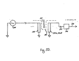
- Figure 5D shows a schematic diagram of a sensor system to include a sensor in accordance with the invention.
- An oscillator 34 provides an input to the drive winding 32 to create the drive field.
- the environmental barrier 35 is located between the drive winding 32 and the movable screening plate 31, and also between the screen 31 and the coil or coils of the sense winding 33a, 33b.
- the output voltage from the sense winding is processed in a demodulator and signal conditioning unit denoted by reference 36 to provide the final output signal 38 from the device.
- the system of Figure 5D facilitates the derivation of the outputs shown in Figure 5B and Figure 5C, the initial transducer output of Figure 5B being present at stage 37 of the system of Figure 5D, and the demodulated output of Figure 5C forming the final output 38 from the system.
- the modulation envelope is designed to be a sinusoidal function of screen position.
- the advantage of this is that there are a wide selection of commercially available converters which will derive a digital position signal from amplitude modulated sine/cosine information.
- the derived modulation envelope can be achieved with rectangular screens 51 and shaped windings 53a/b, or by shaped screens 61 and rectangular windings 63a, 63b or indeed by a shaping of both elements.
- the screen pitch, Ps is made significantly less than the winding pitch, Pw.
- the modulation envelope is normally determined by the shape of the sense winding, which characteristically will have a tapered form, as shown in Figure 6C. While screening efficiency and hence achievable accuracy tends to be reduced in this configuration this is not necessarily disadvantageous in elongated working stroke designs.
- FIG. 7A The screen/winding combinations shown in planar form in Figures 6A, 6B and 6C all have equivalents in solenoidal geometries, as shown in Figures 7A, 7B and 7C.
- the arrangement of Figure 7A provides piecewise linear modulation, with a cylindrical screen 81, constant axial turn density in the sense winding 83, and phase reversal centrally along its axial extent.
- Sinusoidal modulation may be achieved by a shaped double-tapered screen 91 a co-operating with a constant density sense winding, such as coil 83 of Figure 6A, or alternatively, a cylindrical screen 91 b of constant cross-section may be employed, in conjunction with a sense winding 93 in which the lineal turn density is sinusoidal.
- solenoidal type windings is in some respects simpler than planar types, and in some respects more complicated. It is simplified in that the field inside a long uniform solenoidal drive winding 112, as shown in Figure 7D, is readily calculated from Ampere's circuital law, and in region 1 has the magnitude where nd is the drive winding turn density, expressed in conductors per meter, and I Sin Wt is the exciting current. B represents flux density and H is field strength. Apart from small regions near the ends, the field will be uniform over the interior volume, will be axial in direction, and will be negligible outside the coil 112.
- Figure 7D also shows a rod or tube 111 of conductive non-ferromagnetic material partially inserted into the solenoid.
- the field will from symmetry be axial.
- the induced current density J in the rod 111 will be circumferential.
- Currents in the rod 111 act to reduce the field within it.
- the field will be unaffected by the presence of the rod. It will have the same value as in region 1.
- regions 1 and 2 there is an area of transition in which the field will have a complex structure not easily calculated. This is the complication mentioned previously.
- the flux per turn in regions 1 and 2 is uniform, but different, and a nett outflow or inflow across the surface of the solenoid is required in the transition region.
- the transition region can thus be defined as that portion of the axial length of the solenoid in which the flux per turn linked by the sense winding varies locally with position.
- Figure 7D shows a solenoidal sense winding or coil 113 with turn density ns and cross section As contained within the drive winding.
- ns and Ar the rod cross-section, will be variable along their lengths.
- a useful simplifying assumption is to neglect penetration of the drive field within the rod. This will be true for high values of drive frequency or rod conductivity.
- the average voltage induced in the sense winding will then be given by where both Ar and ns are functions of length (I).
- Equation (12) can be calculated in a straightforward way in regions 1 and 2.
- the situation will normally be further simplified by choosing a rod of constant cross section, and varying only the turn density of the sense coil. This also makes possible an analytic solution for the actual field within a non-ideal rod, which then becomes a classical problem for Bessel functions.
- a final simplifying assumption allows the problem of analysing the transition region to be disposed of. If the sense windings are evenly distributed, or if their gradient of change is low relative to the width of the transition region, the effect of the transition region may be neglected.
- Region 2 increases at the expense of region 1.
- the transition region T moves with the rod, without changing its configuration. Given that there has been no significant change in turn density over the increment of motion, the flux linkage contribution of the transition region does not change. Even if the flux linked by each individual turn within the region is not known, the same flux will be linked by the same number of turns, after the increment of motion.
- the drive field has a substantially even distribution over the area of the sense winding in the absence of the screen, at least on the axis of motion.
- the drive field should have a constant value along any line in or parallel to this direction of relative screen and sense winding displacement, although it may vary at right angles to the direction of motion, so that the field density or any given such line is not necessarily the same as that along another and parallel line.
- Figures 9, 10 and 11 show, respectively, a linear planar configuration of screened inductance sensor, a rotary planar construction, and finally a rotary cylindrical embodiment, in each case incorporating a barrier corresponding to the stainless steel tube 2 of the embodiment of Figure 1.
- a screen 121 moves linearly through a space sealed off by a barrier 124 from an external environment in which drive winding 122 and sense winding 123 are disposed. Again there is total separation of the environment in which the screen 121 moves from that in which the sense and drive windings are located.
- Figure 10 shows a rotary planar configuration of sensor according to the invention, in which screens 131 are defined by either radially extending fins or by conductive portions on a radially disposed disc.
- the screens rotate with a shaft 135 which is located within an environment sealed off by barrier 134.
- the drive field is established by solenoidal coil 132, which creates a drive field extending substantially parallel to the axis of rotation of the screens.
- the sense winding may be a single winding unit located to one side of the screen, but in the arrangement shown in the drawing, in order to provide a symmetrical construction, sense winding 133 is defined by portions located to each axial side of the barrier 134 within which means screens 131 are located.
- FIG 11 illustrates a rotary cylindrical construction, in which the screens 141 are defined by arcuate segmental conductive portions disposed on the periphery of a cylinder 145a mounted for rotation on a shaft 145.
- This rotary assembly is enclosed within a tubular barrier 144, with the winding elements of the sensor disposed on a spool located around the exterior of the barrier, the winding assembly comprising drive winding 142 and sense windings 143.
- Figures 3 and 4 illustrate transducer configurations applicable to the present invention in which the sense winding has a single coil.
- Figure 5A illustrates an arrangement in which the sense winding has dual coils, wound in phase/anti-phase, and this arrangement is used in many practical applications of the device of the invention.
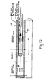
- Figure 12 depicts a practical example of the single sense coil arrangement of Figures 3 and 4.
- a so-called long stroke version of a linear-cylindrical transducer is shown in this Figure, which corresponds in its general construction with the arrangement of Figure 1.
- the plunger of Figure 1 is replaced by a solid rod 151 movable inside tubular barrier 152, surrounded by drive 156 and sense 157 windings. Reference id indicates the extent of rod penetration.
- the phase/anti-phase sense windings of Figure 1, also shown in Figure 7A, are replaced by a single solenoidal sense coil 157 wound over the full extent of the transducer. Thus there is no reversal of winding direction along the length of the sense winding.
- the quantity wl can be deduced by including a mutual inductor M in series with the drive and sense windings, as shown in the schematic system diagram of Figure 13.
- the ratio can be easily calculated using electronic converters.
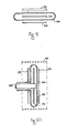
- FIG. 14A An example of a transducer using such a system is shown in Figure 14A.
- Float 161 is pivotably connected to screen 162, which is in the form of an arcuate segment and defines the screen of the device.
- Drive 163 and sense 164 windings are provided, as shown in section in Figure 14B and schematically in Figure 14C.
- the screen is enclosed within barrier 165. The entire unit may be surrounded by an optional ferromagnetic external flux return path or cover 166.
- the general device geometry is that of the rotary-planar type already described, but only a portion of the notional disc surface is used for the sense windings in this case.
- Figure 14C illustrates possible sense winding geometries (for type W modulation).
- the configuration of the system in this elongated working/ construction may be adapted to provide a transfer function complementary to that relating fluid level to the angle of the measurement arm, to provide an overall linear response for the system.
- the environmental barrier for the device as illustrated in Figure 14A is in the general form of box, D-shaped in cross-section, which surrounds the screen and is bolted onto or welded to a wall of the tank within which level is to be measured.
- Rotary cylindrical geometries may also be provided for applications of this kind.
- the primary advantage of a float-type system as compared with the plunger-type configurations previously described is that the transducer generally projects to a lesser extent to the exterior of the region within which level is to be measured, while the tubular float-type arrangement is especially favourable in withstanding high pressure differences, in that it provides advantageous stressing and structural features.
Landscapes
- Physics & Mathematics (AREA)
- General Physics & Mathematics (AREA)
- Measurement Of Length, Angles, Or The Like Using Electric Or Magnetic Means (AREA)
- Transmission And Conversion Of Sensor Element Output (AREA)
Claims (10)
Applications Claiming Priority (2)
| Application Number | Priority Date | Filing Date | Title |
|---|---|---|---|
| IE130586A IE59150B1 (en) | 1986-05-16 | 1986-05-16 | Transducers for hostile environments |
| IE130586 | 1986-05-16 |
Publications (2)
| Publication Number | Publication Date |
|---|---|
| EP0247000A1 EP0247000A1 (fr) | 1987-11-25 |
| EP0247000B1 true EP0247000B1 (fr) | 1990-12-05 |
Family
ID=11025238
Family Applications (1)
| Application Number | Title | Priority Date | Filing Date |
|---|---|---|---|
| EP87730055A Expired - Lifetime EP0247000B1 (fr) | 1986-05-16 | 1987-05-13 | Transducteur pour environnements hostiles |
Country Status (7)
| Country | Link |
|---|---|
| US (1) | US4887465A (fr) |
| EP (1) | EP0247000B1 (fr) |
| JP (1) | JPS6324124A (fr) |
| CA (1) | CA1296918C (fr) |
| DE (1) | DE3766539D1 (fr) |
| GB (1) | GB2190507B (fr) |
| IE (1) | IE59150B1 (fr) |
Cited By (1)
| Publication number | Priority date | Publication date | Assignee | Title |
|---|---|---|---|---|
| DE102013200698A1 (de) * | 2013-01-18 | 2014-07-24 | Zf Friedrichshafen Ag | Spulenanordnung mit zwei Spulen |
Families Citing this family (11)
| Publication number | Priority date | Publication date | Assignee | Title |
|---|---|---|---|---|
| GB8813632D0 (en) * | 1988-06-09 | 1988-07-13 | Dover & Partners Ltd | Position transducer |
| CA2062608A1 (fr) * | 1991-04-18 | 1992-10-19 | Steven W. Tanamachi | Capteur en deux parties assurant le couplage de signaux optique et le couplage de puissance du transformateur |
| EP0743508A2 (fr) * | 1995-05-16 | 1996-11-20 | Mitutoyo Corporation | Capteur de position employant un courant d'induction |
| US6474158B2 (en) | 1995-09-19 | 2002-11-05 | Czarnek And Orkin Laboratories, Inc. | Apparatus for measuring displacement and method of use thereof |
| EP0855018B1 (fr) * | 1995-09-19 | 2002-08-14 | Czarnek And Orkin Laboratories, Inc. | Capteur inductif pour surveiller le niveau et du deplacement d'un fluide et de deplacements |
| US6192754B1 (en) | 1995-09-19 | 2001-02-27 | Czarnek And Orkin Laboratories, Inc. | Sensor system for measuring displacements |
| JP4476717B2 (ja) * | 2004-06-30 | 2010-06-09 | オークマ株式会社 | 電磁誘導型位置センサ |
| DE102006026543B4 (de) | 2006-06-07 | 2010-02-04 | Vogt Electronic Components Gmbh | Lagegeber und zugehöriges Verfahren zum Erfassen einer Position eines Läufers einer Maschine |
| US8222891B2 (en) * | 2009-05-01 | 2012-07-17 | Hewlett-Packard Development Company, L.P. | Compensating for position errors in displacement transducers |
| US9086314B2 (en) | 2011-12-02 | 2015-07-21 | Czarnek & Orkin Laboratories, Inc. | Battery-less active float for inductive sensor for monitoring fluid level and displacement |
| DE202014102940U1 (de) * | 2014-06-27 | 2014-08-28 | Bürkert Werke GmbH | Ventil mit einem Stößel und einem Sensor |
Citations (1)
| Publication number | Priority date | Publication date | Assignee | Title |
|---|---|---|---|---|
| EP0182085A2 (fr) * | 1984-10-19 | 1986-05-28 | Kollmorgen Corporation | Capteur de position et de vitesse |
Family Cites Families (23)
| Publication number | Priority date | Publication date | Assignee | Title |
|---|---|---|---|---|
| GB237279A (en) * | 1924-07-18 | 1926-02-11 | Stephan Loffler | Improvements in or relating to liquid level indicators for high pressure steam boilers and like liquid containers |
| US2370099A (en) * | 1944-02-03 | 1945-02-20 | John F Werder | Liquid level gauge |
| US2424766A (en) * | 1944-06-19 | 1947-07-29 | Builders Iron Foundry | Telemetric apparatus |
| GB811417A (en) * | 1957-07-16 | 1959-04-02 | Gen Electric Co Ltd | Improvements in or relating to liquid level indicators |
| US3484678A (en) * | 1966-01-27 | 1969-12-16 | Kaman Sciences Corp | Linear differential transformer transducer with nonmagnetic core |
| DE2242951B2 (de) * | 1972-08-31 | 1976-09-16 | Siemens AG, 1000 Berlin und 8000 München | Stellungsanzeige fuer einen in einem kernreaktor verfahrbaren steuerstab |
| US4047103A (en) * | 1975-02-04 | 1977-09-06 | Westinghouse Electric Corporation | Eddy current position indicating apparatus for measuring displacements of core components of a liquid metal nuclear reactor |
| GB1499417A (en) * | 1975-02-25 | 1978-02-01 | Vnii Str I Dorozh Mash Ussr | Inductive transducers |
| DD118327A1 (fr) * | 1975-02-28 | 1976-02-20 | ||
| US4006637A (en) * | 1975-05-16 | 1977-02-08 | Yohei Kinosita | Electro-mechanical displacement transducer |
| JPS53156A (en) * | 1976-06-24 | 1978-01-05 | Mitsubishi Electric Corp | Position detector |
| FR2395566A1 (fr) * | 1977-06-21 | 1979-01-19 | Merlin Gerin | Capteur de position des barres de controle pour reacteur nucleaire |
| GB2012431A (en) * | 1977-08-17 | 1979-07-25 | Hayter J E | Electromagnetic Position Transducer Uses Eddy Currents Induced in Conductive Member |
| US4297698A (en) * | 1977-11-02 | 1981-10-27 | Pneumo Corporation | 360 Degree linear variable phase transformer |
| JPS5486370A (en) * | 1977-12-21 | 1979-07-09 | Sakura Sokki Kk | Level gauge |
| US4282485A (en) * | 1978-05-22 | 1981-08-04 | Pneumo Corporation | Linear variable phase transformer with constant magnitude output |
| GB2027207B (en) * | 1978-05-31 | 1982-09-29 | Armstrong Patents Co Ltd | Vehicle suspension systems |
| GB2031157B (en) * | 1978-09-28 | 1982-11-17 | Lucas Industries Ltd | Displacement transducer |
| ZA794794B (en) * | 1978-09-28 | 1980-08-27 | Lucas Industries Ltd | Displacement transducers |
| US4321826A (en) * | 1980-04-28 | 1982-03-30 | Bibbee William C | Flowmeter for fluid flow through weirs and parshall flumes |
| JPS59191313A (ja) * | 1983-04-14 | 1984-10-30 | Noble Sangyo Kk | 超小型超高速応答差動検知装置 |
| GB2163259B (en) * | 1984-05-02 | 1988-08-10 | Westinghouse Electric Corp | Rod position indication system |
| US4631537A (en) * | 1984-05-02 | 1986-12-23 | Westinghouse Electric Corp. | Method for temperature compensating a rod position indication system |
-
1986
- 1986-05-16 IE IE130586A patent/IE59150B1/en not_active IP Right Cessation
-
1987
- 1987-05-13 GB GB8711223A patent/GB2190507B/en not_active Expired - Lifetime
- 1987-05-13 EP EP87730055A patent/EP0247000B1/fr not_active Expired - Lifetime
- 1987-05-13 DE DE8787730055T patent/DE3766539D1/de not_active Expired - Lifetime
- 1987-05-14 US US07/049,578 patent/US4887465A/en not_active Expired - Lifetime
- 1987-05-14 JP JP62118046A patent/JPS6324124A/ja active Pending
- 1987-05-15 CA CA000537304A patent/CA1296918C/fr not_active Expired - Lifetime
Patent Citations (1)
| Publication number | Priority date | Publication date | Assignee | Title |
|---|---|---|---|---|
| EP0182085A2 (fr) * | 1984-10-19 | 1986-05-28 | Kollmorgen Corporation | Capteur de position et de vitesse |
Cited By (1)
| Publication number | Priority date | Publication date | Assignee | Title |
|---|---|---|---|---|
| DE102013200698A1 (de) * | 2013-01-18 | 2014-07-24 | Zf Friedrichshafen Ag | Spulenanordnung mit zwei Spulen |
Also Published As
| Publication number | Publication date |
|---|---|
| DE3766539D1 (de) | 1991-01-17 |
| CA1296918C (fr) | 1992-03-10 |
| GB2190507B (en) | 1990-08-29 |
| IE861305L (en) | 1987-11-16 |
| EP0247000A1 (fr) | 1987-11-25 |
| IE59150B1 (en) | 1994-01-12 |
| GB8711223D0 (en) | 1987-06-17 |
| GB2190507A (en) | 1987-11-18 |
| JPS6324124A (ja) | 1988-02-01 |
| US4887465A (en) | 1989-12-19 |
Similar Documents
| Publication | Publication Date | Title |
|---|---|---|
| EP0247000B1 (fr) | Transducteur pour environnements hostiles | |
| US6118271A (en) | Position encoder using saturable reactor interacting with magnetic fields varying with time and with position | |
| CA2232544C (fr) | Capteur inductif pour surveiller le niveau et du deplacement d'un fluide et de deplacements | |
| EP0446969B1 (fr) | Dispositif de détection de la position linéaire | |
| US4986124A (en) | Screened inductance sensors, especially sensors for level measurement | |
| US4667158A (en) | Linear position transducer and signal processor | |
| US6642710B2 (en) | Position sensor | |
| EP0349547A1 (fr) | Detecteurs de deplacement inductifs. | |
| EP0366227B1 (fr) | Appareil de mesure de déplacement | |
| US6803758B1 (en) | Non-contact magnetically variable differential transformer | |
| US20150354991A1 (en) | Coil arrangement having two coils | |
| GB2106651A (en) | Displacement indication device | |
| JPS61159101A (ja) | 位置および速度センサ | |
| US5456013A (en) | Inductive tilt sensor and method for measuring tooth mobility | |
| US5867022A (en) | Inductive angle-of-rotation sensor having rotatable magnetically conductive element within single winding coil | |
| WO2005119179A1 (fr) | Detecteur de deplacement magnetique | |
| CN100458842C (zh) | 电磁感应编码的机械计数器 | |
| US7511476B2 (en) | Electromagnetic sensor systems and methods of use thereof | |
| JPH0792395B2 (ja) | センサつき面積式流量計および流量計測方法 | |
| RU2044999C1 (ru) | Преобразователь линейного перемещения | |
| JP2000275088A (ja) | 液面検出装置 | |
| SU1262291A1 (ru) | Устройство дл определени границы раздела сред | |
| SU922519A1 (ru) | Устройство дл измерени уровн жидкости | |
| GB2049939A (en) | Inductive displacement transducers | |
| SU475499A1 (ru) | Бесконтактный датчик перемещени |
Legal Events
| Date | Code | Title | Description |
|---|---|---|---|
| PUAI | Public reference made under article 153(3) epc to a published international application that has entered the european phase |
Free format text: ORIGINAL CODE: 0009012 |
|
| AK | Designated contracting states |
Kind code of ref document: A1 Designated state(s): DE FR GB IT NL |
|
| 17P | Request for examination filed |
Effective date: 19880420 |
|
| 17Q | First examination report despatched |
Effective date: 19890628 |
|
| GRAA | (expected) grant |
Free format text: ORIGINAL CODE: 0009210 |
|
| AK | Designated contracting states |
Kind code of ref document: B1 Designated state(s): DE FR GB IT NL |
|
| REF | Corresponds to: |
Ref document number: 3766539 Country of ref document: DE Date of ref document: 19910117 |
|
| ITF | It: translation for a ep patent filed | ||
| ET | Fr: translation filed | ||
| PG25 | Lapsed in a contracting state [announced via postgrant information from national office to epo] |
Ref country code: GB Effective date: 19910513 |
|
| ITTA | It: last paid annual fee | ||
| PLBE | No opposition filed within time limit |
Free format text: ORIGINAL CODE: 0009261 |
|
| STAA | Information on the status of an ep patent application or granted ep patent |
Free format text: STATUS: NO OPPOSITION FILED WITHIN TIME LIMIT |
|
| 26N | No opposition filed | ||
| GBPC | Gb: european patent ceased through non-payment of renewal fee | ||
| PGFP | Annual fee paid to national office [announced via postgrant information from national office to epo] |
Ref country code: NL Payment date: 19940531 Year of fee payment: 8 |
|
| PG25 | Lapsed in a contracting state [announced via postgrant information from national office to epo] |
Ref country code: NL Effective date: 19951201 |
|
| NLV4 | Nl: lapsed or anulled due to non-payment of the annual fee |
Effective date: 19951201 |
|
| PGFP | Annual fee paid to national office [announced via postgrant information from national office to epo] |
Ref country code: FR Payment date: 20060519 Year of fee payment: 20 Ref country code: DE Payment date: 20060519 Year of fee payment: 20 |
|
| PGFP | Annual fee paid to national office [announced via postgrant information from national office to epo] |
Ref country code: IT Payment date: 20060531 Year of fee payment: 20 |