EP0247170B1 - Ameliorations apportees a des pompes a diaphragme vibrant - Google Patents
Ameliorations apportees a des pompes a diaphragme vibrant Download PDFInfo
- Publication number
- EP0247170B1 EP0247170B1 EP87900200A EP87900200A EP0247170B1 EP 0247170 B1 EP0247170 B1 EP 0247170B1 EP 87900200 A EP87900200 A EP 87900200A EP 87900200 A EP87900200 A EP 87900200A EP 0247170 B1 EP0247170 B1 EP 0247170B1
- Authority
- EP
- European Patent Office
- Prior art keywords
- chamber
- pump
- casing
- diaphragm
- armature
- Prior art date
- Legal status (The legal status is an assumption and is not a legal conclusion. Google has not performed a legal analysis and makes no representation as to the accuracy of the status listed.)
- Expired - Lifetime
Links
Images



Classifications
-
- F—MECHANICAL ENGINEERING; LIGHTING; HEATING; WEAPONS; BLASTING
- F04—POSITIVE - DISPLACEMENT MACHINES FOR LIQUIDS; PUMPS FOR LIQUIDS OR ELASTIC FLUIDS
- F04B—POSITIVE-DISPLACEMENT MACHINES FOR LIQUIDS; PUMPS
- F04B41/00—Pumping installations or systems specially adapted for elastic fluids
- F04B41/02—Pumping installations or systems specially adapted for elastic fluids having reservoirs
-
- F—MECHANICAL ENGINEERING; LIGHTING; HEATING; WEAPONS; BLASTING
- F04—POSITIVE - DISPLACEMENT MACHINES FOR LIQUIDS; PUMPS FOR LIQUIDS OR ELASTIC FLUIDS
- F04B—POSITIVE-DISPLACEMENT MACHINES FOR LIQUIDS; PUMPS
- F04B45/00—Pumps or pumping installations having flexible working members and specially adapted for elastic fluids
- F04B45/04—Pumps or pumping installations having flexible working members and specially adapted for elastic fluids having plate-like flexible members, e.g. diaphragms
- F04B45/047—Pumps having electric drive
Definitions
- This invention relates to a vibratory diaphragm pump which is particularly, but not exclusively, suitable for intermittent operation for example in a fluidic system for intermittent compression therapy.
- the pump supplies pressurized fluid, normally air, to one or more inflatable garments when the pump is activated and allows air to evacuate from the or each garment through the pump casing when the pump is deactivated in a cylic operation.
- the garments typically comprise a sealed double-skinned sleeve which more usually is worn about a patient's limb to be treated and which cylically is inflated and deflated so as to apply to that limb an intermittent compressive force.
- US-A-3671151 (B Duke et al) describes a vibratory pneumatic diaphragm pump in which a lower chamber housing a diaphragm valve and armature assembly and driving means is provided together within an upper chamber to which the diaphragm assembly is connected.
- the pump is a low power aquarium pump and air is drawn into the lower chamber by the diaphragm assembly and then, after pumping, transferred via a conduit to an upper chamber.
- the upper chamber is a manifold from which air may be selectively allowed to escape through one or more of a number of delivery tubes.
- an inlet to the pump is provided by an upper chamber and air is drawn into the lower chamber as the valve and diaphragm assembly operates. Thereafter the pumped air issues directly into the lower chamber from which it can discharge through an outlet.
- the air which has been pumped is caused to expand into a substantial lower chamber.
- the larger volume of the lower chamber allows fluctuations in the supply of pumped air to be substantially eradicated so that a smooth flow prevails.
- the lower expansion chamber also acts as a silencing medium so that the pump is able to run quietly and smoothly.
- the invention provides a pneumatic vibratory diaphragm pump comprising a casing having a first chamber and a second chamber, an oscillatory armature within said second chamber to actuate a diaphragm of at least one diaphragm and valve assembly and drive means to cause oscillatory movement of the armature, characterised in that said first chamber has an inlet by which air can be drawn into the first chamber from outside the casing, each diaphragm and valve assembly being connected with said first chamber so as to induce air to be pumped thereby from said first chamber and to discharge air into said second chamber whereby the lower chamber provides an expansion chamber for the pump in that said second chamber has an outlet from which the discharged air issues.
- the first and second chambers may be separated by a partition which isolates said chambers from one another during operation of the pump and wherein an inlet for each diaphragm and valve assembly accommodated in the second chamber communicates with said first chamber through said partition.
- the second chamber may be provided by a lower shell of the casing and the first chamber is provided by an upper shell of the casing, said upper and lower shells being secured together in superposed fluid-tight relationship.
- the first chamber may also accommodate an oscillatory armature to actuate a diaphragm of at least one further diaphragm and valve assembly and drive means to cause oscillatory movement of the armature in the first chamber, each diaphragm and valve assembly within said casing being arranged so as to induce air to be pumped thereby from the first chamber and to discharge air into the second chamber from whence the discharged air issues from said outlet.
- the armature in said first chamber may extend in the opposite direction to that of the armature in said second chamber and the respective drive means for each armature is disposed at opposed ends of the casing in the respective chambers.
- venting means may be provided to allow air which has been discharged from the casing into a container to return therefrom and exhaust from the casing when the pump is inactive said venting means being arranged to close said exhaust when the pump is operative.
- operation of the venting means to open and close the exhaust may be automatic upon respectively deactivating and activating the pump, said venting means comprising a valve controlled output from the casing independent of said outlet means.
- the drive means is coupled to control means for causing intermittent operation of the pump.
- the armature may comprise a main body portion carrying at one end thereof a pair of opposite polarity magnets in which the main body portion has a pivotal element by which the armature may be pivotally connected to a pair of diaphragm assemblies adjacent opposed sides of the body portion, and wherein a resilient element interconnects the main body portion with an end part of the armature by which end part the armature can be mounted for vibratory movement of the body part relative to the end part.
- the resilient element comprises a spring steel plate.
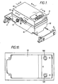
- a vibratory diaphragm pump 'P' comprises a casing 10 which is a cast aluminium structure having an open-top elongate lower shell 12 and an upper shell 14 which is fitted to the lower shell so as to provide a lid.
- a partition 15 is interposed between the upper end lower shells so as to create an outlet chamber 16 in the lower shell and an inlet chamber 17 in the upper shell. The partition and its relationship to chamber 16 and 17 will be described in more detail below.
- the lower shell includes sidewalls 12a, 12b; endwalls 12c, 12d and a base 12e.
- One end of the lower shell receives a laminated ferrous E-stack 18 whose central limb 18a carries a driving coil 20.
- the E-stack stands on raised plinths 19, 19a formed in opposed corners of the lower shell adjacent endwall 12d.
- An armature assembly generally desingated by reference numeral 22 extends longitudinally of the lower shell and centrally thereof immediately above a rib structure formed in the base and comprising longitudinal rib 21 and transverse rib 21a.
- the armature 22 has one of its ends secured in a downwards tapered socket 24 provided internally of the lower shell integrally formed with end wall 12c.
- the opposite end of the armature terminates in a flanged head 26 adjacent the E-stack 18.
- the flanged head incorporates a pair of spaced magnets 28 and 30 of opposite polarity which are seated in side-by-side relationship on a common keep plate in close proximity to the E-stack limbs.
- the flanged head 26 is integral with a main body portion 34 of the armature which is connected to an end part 36 by means of a flat metallic leaf spring 38.
- the armature resiliently is mounted with respect to the lower shell and is caused to oscillate about its fixed end part 36 across the exposed ends of the E-stack limbs when electrical current is passed through coil 18.
- Diaphragm valve assemblies 28 and 30 are disposed one on each side of the main body portion of the armature and each assembly comprises a valve body 28a, 30a and a flexible cup-shaped diaphragm 28b, 30b respectively, described in more detail later. Both diaphragms of the diaphragm valve assemblies 28 and 30 are connected to the armature 22 by a resilient linkage 40.
- the main body portion 34 of the armature is formed with a square cross-sectional transverse through bore 42 in which a resiliently pivotal linkage block 44 is received with clearance.
- Block 44 resiliently is mounted within bore 42 by a fixed pin 46 which extends through a vertical bore 48 formed in the block 44 and whose axis is perpendicular to the axis of through bore 41.
- Vertical bore 48 accommodates a resilient material 50 which surrounds the fixed pin 46.
- a pair of linkage arms 52 and 54 respectively extend outwardly from opposed faces of the linkage block 44. The arms terminate in flat cross-heads by which the linkage is connected internally of the operative faces of the diaphragms 28b and 30b, respectively.
- the linkage block 44 can pivot resiliently within bore 42 about fixed pin 46 as the armature body oscillates.
- the resilient linkage allows the diaphragms to be flexed evenly and squarely with respect to the notional longitudinal axis of the lower shell 12 notwithstanding the arcuate path described by the oscillatory movement of the armature.
- Such a construction greatly reduces the stresses to which the diaphragms might otherwise by subjected, increases longivity of the diaphragms and, of course, increases the volume of air pumped thereby and hence the performance of the pump.
- the armature spring 38 comprises a straight metal strip which is anchored in end part 36, it is able to deflect by substantially the same amount either side of its rest position without bias in either direction, thereby operating the opposed diaphragms equally.
- the armature body and end part preferably is moulded from a plastics material, the spring 38 having its opposite ends embedded in the end part 36 and main body part 34 , respectively, during the moulding process.
- the magnets 28 and 30 together with their common keep plate also are incorporated into the armature head 26 at the time of moulding.
- the end part 36 is formed as a downwardly tapered peg which mates with the tapered socket 34 . Therefore, the armature and diaphragm valve assemblies can be pre-assembled whereafter that assembly can be mounted in position by driving the tapered peg end part 36 into its mating socket 34.
- the diaphragms are formed from an elastomeric material such as rubber or a rubber compound or neoprene into a dished element having an internal diaphragm cavity.
- the diaphragm valve assemblies 28 and 30 are mounted within the lower shell in opposed relationship one on each side of the armature.
- Diaphragm valve assembly 28 is secured to sidewall 12a by a fixing screw which locates in a fixing boss of the valve body, the open ends of the inlet and outlet cavities of the valve body being sealed by a gasket 'G1'.
- Diaphragm valve assembly 30 similarly is secured to sidewall 12b with the imposition of gasket 'G2' . Both diaphragm valve assemblies are located with their inlet nozzles 28c and 30c upstanding uppermost of the lower shell.
- partition 15 which is formed from a plastics material closes the open top of the lower shell and isolates the upper chamber 17 from the lower chamber 16 and also seals the casing so that at least lower chamber 16 is fluid-tight.
- the partition has a peripheral flange 15a which seals around the interface join between the upper and lower shells.
- the partition includes a pair of spaced apertures 15b , 15c which are in registry with and seal around the inlet nozzles 28c and 30c of diaphragm valve assemblies 28 and 30 whereby the diaphragm valve assemblies are in communication with the upper chamber 17 of the casing.
- the upper shell is formed with a pair of inlet tubes 56, 58 through which air is drawing into the upper chamber from outside the casing via a filter cavity 59.
- the filter cavity is provided with a suitable filter 59a through which induced air passes prior to entering the chamber via the inlet tubes.
- the induced air passes through a labyrinth provided by locating the free ends of the inlet tubes in blind sockets 60, 62 respectively upstanding from the top surface of the partition and which are of larger diameter than the inlet tubes.
- the diaphragms are flexed alternatively and air is drawn into the upper chamber via the filter cavity, the inlet tubes, the inlet labyrinth sockets and thence through the inlet nozzles of the diaphragm valve assemblies whereafter the induced air charge of each diaphragm valve assembly is discharged through its outlet orifice into the lower chamber 16 of the casing.
- Sidewall 12b of the lower casing is provided with an outlet nozzle 'N' adjacent endwall 12c through which discharged air is expelled from the casing.
- the pump In applications where the pump is employed for inflating a garment of the kind used in intermittent compression therapy, the pump is activated intermittently and the outlet nozzle normally is connected to a pressure control device, through which air expelled from the pump is passed before issuing into a garment.
- the lower chamber 16 is under pressure of a variable amount up to e.g. 200 mm Hg above atmospheric pressure.
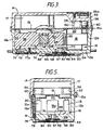
- Figures 2 and 3 - 5 show the underside of the lower casing 12 of the pump on which base 12e is formed with an upstanding annular wall 64.
- base 12e Centrally within the annular wall the base has a blind annular bore 66 occupied by an upstanding cylindrical platform 68.
- Platform 68 is formed with a through bore 70 which passes through transverse rib 21a and communicates internally of chamber 16.
- the upper surface of platform 68 is substantially flush with a shoulder 72 set into base around the mouth of the annular bore.
- An exhaust passageway 74 is formed through the longitudinal rib of the lower shell one end of which opens into the annular bore 6 and the opposite end of which opens into an outlet cavity 76 formed adjacent end wall 12e of the base.
- the outlet cavity may be filled with an air permeable noise insulating material 77 held in place by a suitable porus cover 77a to allow air to be exhausted therethrough.
- a transfer passageway 78 extends through the transverse rib 21a of the base and has one open end 79 located within that area of the base defined by the annular wall 64.
- Within the lower shell sidewall 12a is formed with an elongate scolloped portion 80, the lowermost end of which includes the other open end 81 of transfer passageway 78.
- Transfer passageway 78 communicates with the upper chamber 17 by means of a transfer tube 78a which depends downwardly from partition 15 and has its free end sealingly seated against the open end 81 of the transfer passageway within the scolloped portion 80 in sidewall 12a.
- the annular bore 66 and through bore 70 are both covered by a disc 82 of flexible non-porous material the periphery of which held on the shoulder 72 by a securing ring 84 and the disc 82 provides a valve to control the flow of air through the bore 70.
- a valve disc actuating plate 86 is held over the valve disc 82 by a flexible diaphragm ring 88 whose inner periphery is secured to the plate 86 and whose outer periphery is secured to the annular wall 64.
- the diaphragm ring and plate assembly thereby covers the base area defined by the annular wall and forms between itself and that base area an enclosed pocket 90.
- the plate can therefore move towards and away from the valve disc upon flexing of the diaphragm ring.
- the face of plate 86 within the pocket 90 is provided with a projection 87 in registry with the valve disc and which pushes downwardly on the valve disc when the actuating plate moves towards the base.
- valve disc 82 and the plate assembly 86, 88 are relaxed whereby the annular bore 66 communicates with the through bore 70 and plate 86 is disengaged from the valve disc 82.
- air is evacuated from the pocket 90 via the transfer passageway 78 and transfer tube 78a because transfer tube opens into upper chamber 17 and air is being drawn in from the upper chamber by the opposed pump diaghragms.
- valve disc actuating plate 86 is drawn towards the base, such movement being allowed by flexing of the diaphragm ring 88, so that the projection carried by plate 86 pushes against the disc 82 and causes it to seat and seal off the through bore 70. Air which is discharged from the diaphragm assemblies cannot then issue through the through bore 70 and therefore is exhausted from the lower shell only through the discharge nozzle 'N' of the pump. When the pump is deactivated, plate 86 returns to its rest position as the diaphragm ring 86 relaxes so that air may be expelled from an inflated garment back through the discharge nozzle, the through bore 70 and thence the annular bore 66 and is exhausted through the outlet cavity 76 via exhaust passageway 74.
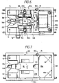
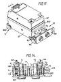
- FIG. 11 and 12 A further pump 'F' embodying the invention is shown in Figures 11 and 12.
- the lower shell of the pump is as described above but the lid 14 is substituted by an upper shell which is of similar overall construction to the lower shell.
- the upper shell also contains a driving coil and an armature assembly which operates a pair of opposed diaphragm assemblies.
- the upper shell 14′ is fitted to the lower shell in top-to-toe relationship whereby the driving coil 18′ in the upper shell is at the opposite end of the casing to that of the lower shell as best seen in Figure in which like partsare designated like reference numerals with the addition of suffix "′" e.g. upper shell 14′.
- the flap valves within the valve bodies in the upper shell 14' are reversed in position so that inlet nozzles become outlet nozzles and outlet orifices become inlet orifices.
- the partition 15′ for this modified pump includes two sets of nozzle apertures 15b′, 15c′, 15d and 15e.
- the inlet nozzles 28c, 30c of the lower shell diaphragm assemblies protrude into the upper chamber 14′ through apertures 15b′, 15c′ and draw air in the direction of arrow 'a'.
- the outlet nozzles 28c′, 30c′ of the upper shell diaphragm assemblies protrude into the lower chamber through apertures 15d and 15e and pump air in the direction of arrow 'a'.
- air is induced from the upper chamber into both the upper and lower diaphragm assemblies and pumped directly into the lower chamber.
- screw fasteners pass through suitable apertures 'f1' in the lower shell and thence through sealing tubes 't' integral with partition 15 and locate in connecting nuts in the upper shell.
- screw fasteners pass through the suitable apertures in the upper shell and thence through sealing tubes 't1' (which extend from the opposite face of the partition 15 to tubes 't') and locate in connecting nuts 's' which secure the E-stack to the lower shell.
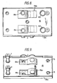
- the assembled pump is supported on a base by mounting asembly 'A' at the right-hand end of the pump casing and mounting assembly 'Z' at the left-hand end of the casing.
- Assembly 'A' comprises mounting cradle 96 ; front plate 98; pump outlet valves V1 and V2, and resilient elements E1, E2.
- Assembly 'Z' comprises a mounting cradle 96a similar to cradle 96 but fixed to the pump casing in a reversed position i.e. in which it is turned through 180° relative to cradle 96 .
- the cradle 96 comprises an elongate 'L'-shaped bracket comprising upright face 714, base 116 and end walls 118, 720 respectively.
- Outrigger feet 122 and 124 extend from
- Assembly 'A' is secured to the pump casing by a pair of similar resilient elements E1, E2 as shown in Figure 5 and with the upright face 114 of cradle 96 engaged against the adjacent end face of the pump casing.
- a resilient element 'E' is formed from an elastomeric material e.g. rubber and comprises a hollow, generally cylindrical body portion,126 having a central bore 128.
- the body portion is outwardly flared at diametrically opposed locations to form upper and lower flat support platforms 130, 132 which are co-extensive with the cylindrical body.
- a first bore 134 is formed through the cylindrical body adjacent upper platform 130 and a similar bore 136, but of smaller diameter, is provided adjacent the lower platform 132. Both bores 134 and 136 have axes parallel to that of central bore 128.
- the upper bore 134 is co-axial with an integral extension tube 138.
- the resilient elements 'E1' and 'E2' are secured at spaced locations adjacent the ends of cradle 96 each by a fixing pin 'p' which passes through lower bore 136 and through aperture 140 formed in upright face 114.
- Tube 138 is received in aperture 142 in the upright face, the aperture 142 being significantly larger than the diameter of the tube.
- a connecting pin 144 extends through tube 138, upper bore 134 and into a portion of the end wall of the pump casing thereby connecting the cradle to the pump.
- each element 'E1', 'E2' engages a base portion of the pump casing (in this construction provided by a rebated corner) and the lower platform seats on a support base.
- front plate 98 carries a pair of pump outlet valves V1, V2and is connected to the upright face 114 of cradle 96 by means of screw-threaded fasteners which pass through spacer tubes 't1' - 't3'.
- the assembly is secured to base 'B' by suitable fasteners which interconnect support studs with the outrigger feet.
- assembly 'Z' comprises a cradle 96a and a pair of the resilient elements E1, E2.
- the resilient elements are mounted within the cradle.
- the base 116a of the cradle is formed with a retaining frame 145, 147 adjacent each end wall of the cradle, each to receive one of the resilient elements E1 and E2.
- the base is formed with an aperture into which the lower support 132 of the associated resilient element is located.
- the resilient element is mounted in the cradle so that the upper support platform stands proud of the cradle end walls ready to receive a base portion of the pump casing.
- the tube 138 extends through oversized aperture 142a in upright face 114 and a connecting pin 144a passes through the tube into the pump casing as described earlier.
- a fixing pin, 'p' extends through the lower bore 136 of the resilient element and is received in an aperture, provided in upright face 114a and in an aperture formed in an opposed wall 'w' of the retaining frame.
- the pump casing is supported on the upper platforms of the resilient elements, but in assembly 'Z' the cradle is offered up to the pump end wall with the upright face of the cradle facing in the opposite direction relative to the pump casing as compared with assembly 'A',
- the resilient elements 'E' in each of the mounting assemblies 'A' and 'Z' allow vibratory motion of the casing and other limited movement caused e.g. by shock forces to be substantially absorbed so that vibratory motion, in particular, is not transmitted to a base which may form a part of an outer enclosure in which the pump casing is housed.
- the arrangement by which the extension tube 138 is received in the oversized aperture 142 or 142a in the upright face 114, 114a of the mounting cradle 96, 96 a respectively permits limited universal movement of the pump casing relative to each monting assembly.
Landscapes
- Engineering & Computer Science (AREA)
- Mechanical Engineering (AREA)
- General Engineering & Computer Science (AREA)
- Reciprocating Pumps (AREA)
Abstract
Claims (10)
Applications Claiming Priority (6)
| Application Number | Priority Date | Filing Date | Title |
|---|---|---|---|
| GB8530514 | 1985-12-11 | ||
| GB858530514A GB8530514D0 (en) | 1985-12-11 | 1985-12-11 | Armature |
| GB8530667 | 1985-12-12 | ||
| GB858530667A GB8530667D0 (en) | 1985-12-12 | 1985-12-12 | Shock absorbing mounting |
| GB8530666 | 1985-12-12 | ||
| GB858530666A GB8530666D0 (en) | 1985-12-12 | 1985-12-12 | Vibratory diaphragm pumps |
Publications (2)
| Publication Number | Publication Date |
|---|---|
| EP0247170A1 EP0247170A1 (fr) | 1987-12-02 |
| EP0247170B1 true EP0247170B1 (fr) | 1991-07-24 |
Family
ID=27262857
Family Applications (1)
| Application Number | Title | Priority Date | Filing Date |
|---|---|---|---|
| EP87900200A Expired - Lifetime EP0247170B1 (fr) | 1985-12-11 | 1986-12-11 | Ameliorations apportees a des pompes a diaphragme vibrant |
Country Status (4)
| Country | Link |
|---|---|
| US (1) | US4877378A (fr) |
| EP (1) | EP0247170B1 (fr) |
| AU (1) | AU6776387A (fr) |
| WO (1) | WO1987003650A1 (fr) |
Families Citing this family (12)
| Publication number | Priority date | Publication date | Assignee | Title |
|---|---|---|---|---|
| PT707468E (pt) * | 1993-07-08 | 2003-10-31 | Aircast Inc | Aparelho para proporcionar compressao intermitente terapeutica para reduzir os riscos de trombose venosa profunda (dvt) |
| US6616413B2 (en) * | 1998-03-20 | 2003-09-09 | James C. Humpheries | Automatic optimizing pump and sensor system |
| GB2339336B (en) * | 1998-06-16 | 2000-08-16 | Huntleigh Technology Plc | Magnetic actuator |
| JP3370653B2 (ja) * | 2000-01-06 | 2003-01-27 | 株式会社テクノ高槻 | 電磁振動型ポンプおよびその製法 |
| CA2327012C (fr) | 2000-11-28 | 2006-09-26 | Duncan Wade | Membrane pour pompe a membrane |
| US6698446B2 (en) | 2002-07-12 | 2004-03-02 | R. Conrader Company | Check valve |
| US9162004B1 (en) * | 2014-04-22 | 2015-10-20 | Prolitec Inc. | Removable cartridge for liquid diffusion device and cartridge insert thereof |
| US9677557B2 (en) * | 2015-01-20 | 2017-06-13 | Hao Hsu | Sleeping system |
| CA2984613C (fr) | 2015-05-05 | 2023-06-20 | Parker-Hannifin Corporation | Pompes a membrane a vide/pression miniatures a carter d'attenuation de bruit |
| US9480767B1 (en) | 2015-10-20 | 2016-11-01 | Prolitec Inc. | Removable cartridge and cap assembly for an air treatment appliance |
| US9486552B1 (en) | 2015-10-20 | 2016-11-08 | Prolitec Inc. | Air treatment appliance |
| CN115788839A (zh) * | 2022-11-23 | 2023-03-14 | 东莞市凯尚实业有限公司 | 一种高压高流量充气机芯 |
Citations (1)
| Publication number | Priority date | Publication date | Assignee | Title |
|---|---|---|---|---|
| US3671151A (en) * | 1970-05-11 | 1972-06-20 | Miracle Pet Products Inc | Combination aquarium pump and gang valve |
Family Cites Families (16)
| Publication number | Priority date | Publication date | Assignee | Title |
|---|---|---|---|---|
| US2109718A (en) * | 1936-07-06 | 1938-03-01 | George W Bayers | Air pump |
| US2471796A (en) * | 1945-10-01 | 1949-05-31 | George A Thiberg | Air pump for aquarium aerators |
| US2764947A (en) * | 1952-03-10 | 1956-10-02 | Autopulse Corp | Liquid fuel pump |
| US2788170A (en) * | 1953-11-02 | 1957-04-09 | Ochiai | Aquarium aerator |
| US3055555A (en) * | 1959-11-12 | 1962-09-25 | Gen Electric | Liquid detergent dispenser |
| US3606588A (en) * | 1969-04-10 | 1971-09-20 | Whirlpool Co | Pressure equalizing means for compressors and the like |
| DE1938430C3 (de) * | 1969-07-29 | 1974-08-29 | Erwin 5650 Solingen Kolfertz | Elektrische Doppelmembranpumpe, z.B. als Luftpumpe zum Belüften von Aquarien |
| DE7132711U (de) * | 1971-08-27 | 1972-01-20 | Kolfertz E | Membranpumpe |
| US4044745A (en) * | 1973-03-14 | 1977-08-30 | Holec, N.V. | Injector pump |
| US3967644A (en) * | 1973-08-01 | 1976-07-06 | Carrier Corporation | Compressor control |
| US4162876A (en) * | 1976-01-28 | 1979-07-31 | Erwin Kolfertz | Electromagnetically driven diaphragm pump |
| JPS53140603A (en) * | 1977-05-16 | 1978-12-07 | Enomoto Maikuroponpu Seisakush | Reciprocating type electromagnetic pump |
| US4264282A (en) * | 1979-01-03 | 1981-04-28 | K. C. Mosier Company | Air compressor apparatus including noise-reducing means |
| JPS55153877A (en) * | 1979-05-21 | 1980-12-01 | Hitachi Metals Ltd | Air pump |
| US4321940A (en) * | 1981-01-19 | 1982-03-30 | Control Devices, Incorporated | Unloader/check valve |
| US4470428A (en) * | 1982-05-21 | 1984-09-11 | Eaton Corporation | Unloader and check valve |
-
1986
- 1986-12-11 WO PCT/GB1986/000759 patent/WO1987003650A1/fr not_active Ceased
- 1986-12-11 AU AU67763/87A patent/AU6776387A/en not_active Abandoned
- 1986-12-11 EP EP87900200A patent/EP0247170B1/fr not_active Expired - Lifetime
- 1986-12-11 US US07/095,171 patent/US4877378A/en not_active Expired - Fee Related
Patent Citations (1)
| Publication number | Priority date | Publication date | Assignee | Title |
|---|---|---|---|---|
| US3671151A (en) * | 1970-05-11 | 1972-06-20 | Miracle Pet Products Inc | Combination aquarium pump and gang valve |
Also Published As
| Publication number | Publication date |
|---|---|
| US4877378A (en) | 1989-10-31 |
| WO1987003650A1 (fr) | 1987-06-18 |
| AU6776387A (en) | 1987-06-30 |
| EP0247170A1 (fr) | 1987-12-02 |
Similar Documents
| Publication | Publication Date | Title |
|---|---|---|
| US4877378A (en) | Vibratory diaphragm pumps | |
| US4828234A (en) | Hydraulic engine mount with self-pumping air bladder | |
| US5893609A (en) | Air pumping system for an automotive seat | |
| AU2001273690A1 (en) | Body pulsating method and apparatus | |
| US4319570A (en) | Tracheal suction pump designed primarily for aspiration purposes | |
| ATE68981T1 (de) | Kardiopulmonaere wiederbelebungsvorrichtung. | |
| CA2243942A1 (fr) | Ensemble de vanne ameliore | |
| KR900009108A (ko) | 호흡장치 | |
| JPH0744766Y2 (ja) | 空気圧縮装置 | |
| US6257842B1 (en) | Silencer and electromagnetic vibrating type pump employing the same | |
| FR2651552B1 (fr) | Vanne et dispositifs utilisant ladite vanne. | |
| CA2984613A1 (fr) | Pompes a membrane a vide/pression miniatures a carter d'attenuation de bruit | |
| CN214304293U (zh) | 微型气泵及按摩器 | |
| CN217784295U (zh) | 一种变压式电磁阀 | |
| CN220395931U (zh) | 一种自动泄压泵及包含该自动泄压泵的血压计 | |
| CN114017282B (zh) | 一种自动泄压泵及包含该自动泄压泵的血压计 | |
| EP0200166A3 (en) | Self-contained lash adjuster with diaphragm-type seal | |
| JP2975281B2 (ja) | 電磁弁 | |
| CN223524576U (zh) | 气阀组件及空气波压力治疗仪 | |
| CN214533473U (zh) | 一种应用于控流泵内的中板结构 | |
| SU926375A1 (ru) | Насосна установка транспортного средства | |
| SU1430599A1 (ru) | Жидкостно-кольцевой вакуумный насос | |
| TH39827A (th) | ปั๊มแบบไดอะแฟรม | |
| JPH0476504U (fr) | ||
| NO973105D0 (no) | Luftfri lakkspröyte, inntaksstempel og innlöpsventilfjær |
Legal Events
| Date | Code | Title | Description |
|---|---|---|---|
| PUAI | Public reference made under article 153(3) epc to a published international application that has entered the european phase |
Free format text: ORIGINAL CODE: 0009012 |
|
| AK | Designated contracting states |
Kind code of ref document: A1 Designated state(s): DE FR GB IT SE |
|
| 17P | Request for examination filed |
Effective date: 19880217 |
|
| 17Q | First examination report despatched |
Effective date: 19880906 |
|
| GRAA | (expected) grant |
Free format text: ORIGINAL CODE: 0009210 |
|
| AK | Designated contracting states |
Kind code of ref document: B1 Designated state(s): DE FR GB IT SE |
|
| REF | Corresponds to: |
Ref document number: 3680530 Country of ref document: DE Date of ref document: 19910829 |
|
| ET | Fr: translation filed | ||
| ITF | It: translation for a ep patent filed | ||
| PG25 | Lapsed in a contracting state [announced via postgrant information from national office to epo] |
Ref country code: SE Effective date: 19911212 |
|
| PLBE | No opposition filed within time limit |
Free format text: ORIGINAL CODE: 0009261 |
|
| STAA | Information on the status of an ep patent application or granted ep patent |
Free format text: STATUS: NO OPPOSITION FILED WITHIN TIME LIMIT |
|
| 26N | No opposition filed | ||
| EUG | Se: european patent has lapsed |
Ref document number: 87900200.4 Effective date: 19920704 |
|
| PGFP | Annual fee paid to national office [announced via postgrant information from national office to epo] |
Ref country code: GB Payment date: 20001017 Year of fee payment: 15 Ref country code: FR Payment date: 20001017 Year of fee payment: 15 |
|
| PGFP | Annual fee paid to national office [announced via postgrant information from national office to epo] |
Ref country code: DE Payment date: 20010217 Year of fee payment: 15 |
|
| PG25 | Lapsed in a contracting state [announced via postgrant information from national office to epo] |
Ref country code: GB Free format text: LAPSE BECAUSE OF NON-PAYMENT OF DUE FEES Effective date: 20011211 |
|
| REG | Reference to a national code |
Ref country code: GB Ref legal event code: IF02 |
|
| PG25 | Lapsed in a contracting state [announced via postgrant information from national office to epo] |
Ref country code: DE Free format text: LAPSE BECAUSE OF NON-PAYMENT OF DUE FEES Effective date: 20020702 |
|
| GBPC | Gb: european patent ceased through non-payment of renewal fee |
Effective date: 20011211 |
|
| PG25 | Lapsed in a contracting state [announced via postgrant information from national office to epo] |
Ref country code: FR Free format text: LAPSE BECAUSE OF NON-PAYMENT OF DUE FEES Effective date: 20020830 |
|
| REG | Reference to a national code |
Ref country code: FR Ref legal event code: ST |
|
| PG25 | Lapsed in a contracting state [announced via postgrant information from national office to epo] |
Ref country code: IT Free format text: LAPSE BECAUSE OF NON-PAYMENT OF DUE FEES Effective date: 20051211 |