EP0247283A2 - Ferrure pour brêler des superstuctures détachables, particulièrement pour véhicules - Google Patents
Ferrure pour brêler des superstuctures détachables, particulièrement pour véhicules Download PDFInfo
- Publication number
- EP0247283A2 EP0247283A2 EP87101998A EP87101998A EP0247283A2 EP 0247283 A2 EP0247283 A2 EP 0247283A2 EP 87101998 A EP87101998 A EP 87101998A EP 87101998 A EP87101998 A EP 87101998A EP 0247283 A2 EP0247283 A2 EP 0247283A2
- Authority
- EP
- European Patent Office
- Prior art keywords
- fitting according
- locking bolt
- cams
- housing
- clamping
- Prior art date
- Legal status (The legal status is an assumption and is not a legal conclusion. Google has not performed a legal analysis and makes no representation as to the accuracy of the status listed.)
- Withdrawn
Links
Images

Classifications
-
- B—PERFORMING OPERATIONS; TRANSPORTING
- B60—VEHICLES IN GENERAL
- B60P—VEHICLES ADAPTED FOR LOAD TRANSPORTATION OR TO TRANSPORT, TO CARRY, OR TO COMPRISE SPECIAL LOADS OR OBJECTS
- B60P7/00—Securing or covering of load on vehicles
- B60P7/06—Securing of load
- B60P7/13—Securing freight containers or forwarding containers on vehicles
Definitions
- the invention relates to a low-tension fitting for detachable superstructures, in particular for vehicles, with a housing with a footprint for the body, a guide element projecting upward from the footprint and a central vertical bore, a tensioning and locking bolt that can be rotated and vertically displaced in the bore has a hammer head and carries a thread on its lower shaft section, and a clamping nut that can be screwed onto the thread of the clamping and locking bolt.
- fittings are known as corner fittings for low-tensioning containers, for example from DE-OS 30 13 371. They are mounted as special parts on the chassis booms of container vehicles. These fittings are heavy components that are matched to the special shape and stress conditions of the container attachment, which are too complex for the attachment of other detachable structures and are usually also unsuitable for construction.
- the invention starts with the knowledge that the use of low-tension fittings is suitable not only for container vehicles but also for all other vehicles provided with bodies.
- the low-tension fitting of the type mentioned at the outset is characterized in that the guide element is formed from four cams projecting upward from the contact surface, the cams are arranged in such a way that they form two pairs of aligned gaps between them, which can at least partially accommodate the hammer head of the clamping and locking bolt, all cams are provided on their top with sloping surfaces that drop outwards, and the tensioning and locking bolt is T-shaped from two essentially identical thick rod segments.
- An essential advantage of the invention lies in the arrangement of the four cams in the configuration described on the contact surface. These four cams together form a guide element.
- the guide elements arranged on the vehicle chassis lead the body into its predetermined position when it is placed on the vehicle chassis.
- the arrangement of the cams with pairs of intermediate spaces preferably arranged crosswise presets two positions of the clamping and locking bolt, in which the latter is held against rotation.
- the tensioning and locking bolt can be formed in the simplest way from two T-shaped pieces of round material which are connected to one another, which costs significantly is cheaper than the specially shaped hammer head bolts required for container clamping devices.
- the preferably generally rectangular low-tension fitting can be fitted under practically all conceivable space conditions and is therefore in no way limited to fastening the structure to the corners of the vehicle chassis.
- the clamping and locking bolt has a transverse bore in the lower shank section and a locking and indicator pin accommodated therein, not only is the clamping nut secured, but also a simple position indicator for the hammer head of the clamping and locking bolt is provided. This hammer head is not visible when the structure is attached.
- This clamping nut is not sensitive to heat and allows positive locking by means of a latch engaging between the grip elements of the clamping nut section.
- a support plate is inserted into an opening on the underside of the housing, which supports a molded rubber body between it and the inner wall of the housing, a resilient torsional compensation is created Avoiding damage helps and extends the lifespan of superstructures and low-tension fittings.
- the low-tension fittings according to the invention are not only suitable for fastening detachable structures on a vehicle chassis. They can also be used to secure containers that can be stacked on top of one another, such as building site living quarters.
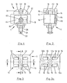
- the low-tension fitting 1 shown in FIG. 1 comprises a housing 10 in the form of a rectangular box which is open on the underside.
- the housing 10 forms on it Top of a footprint 12 on which the support plate (not shown) of the structure to be clamped comes into contact.
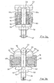
- the upper side of the housing 10 forming the contact surface 12 has a central, vertical through-hole 11, which can be seen particularly in FIGS. 3a to c.
- cams 15 project upwards from the contact surface 12, which together form a guide element 14.
- the cams 15 have a rectangular base surface, from which they initially rise with essentially vertical side walls.
- the cams 15 are provided in the upper region with inclined surfaces 18 extending in the transverse and longitudinal directions. These inclined surfaces 18 serve to guide the support plate of the structure when it is placed on the contact surface 12 and therefore fall outward in the direction of the circumference of the low-tension fitting 1.
- the sloping surfaces 18 run upwards into rounded tips 19 of the cams 15.
- the four cams 15 are arranged symmetrically on the top of the housing 10 such that they form between them a first pair of spaces 16a and 16b which are aligned in their longitudinal direction and a second pair of spaces 17a and 17b which are aligned with one another (FIG. 3c).
- the first pair of intermediate spaces 16a, 16b lies between the facing long edges of the cams 15; the second gap pair 17a, 17b lies between the opposite short edges of the cams 15.
- the crossbar of the T-shaped clamping and locking bolt 20 forms a hammer head 22.
- a first rest position it lies in the first intermediate space pair 16a, 16b in such a way that it does not project laterally beyond the outer contours of the guide element 14.
- the hammer head 22 projects laterally beyond the outer contour of the guide element 14 and is accommodated in the other pair of intermediate spaces 17a, 17b.
- the hammer head 22 engages with its end regions over the support plate of the structure lying on the contact surface 12 and clamps it down.
- the lower shaft section 24 of the clamping and locking bolt 20 is provided with a thread 26 onto which a clamping nut 50 (FIGS. 3a, 3b and 5) is screwed.
- the clamping nut 50 is loosened and the clamping and locking bolt 20 is pushed upwards until it is above the tips 19 of the cams 15 and can be rotated.
- the rounding of the tips 19 facilitates this changeover of the hammer head 22 from one pair of interstices to the other.
- the hammer head 22 of the clamping and locking bolt 20 is at most as long as the longer horizontal outer edge of the guide element 14, but longer than that shorter horizontal edge of the guide element 14, since otherwise it could not overlap the support plate.
- the hammer head is no longer than the smallest width of the contact surface 12 and preferably just as long as this smallest width of the standing surface 12. This is shown particularly clearly in FIG.
- the tensioning and locking bolt 20 is formed from two rod segments 28a, 28b, which are connected to one another in a T-shape.
- the bar segments are preferably simple round material pieces.
- the round material piece 28a forming the hammer head 22 is flattened on the underside in order to form a larger contact surface on the braced support plate.
- the other piece of body material 28b carries in its lower shaft section 24 a thread 26 onto which the clamping nut 50 is screwed. Below the thread 26, a transverse bore 25 is provided, which receives a locking and indicator pin 27. On the one hand, this secures the clamping nut against undesired falling off, and on the other hand shows the respective position of the hammer head 22, which is no longer visible when the structure is attached.
- a support plate 30 is provided, which can be seen in particular in FIGS. 3a and 3b and is received in the interior of the housing 10.
- the support plate 30 has a central through bore 32 through which the tensioning and locking bolt 20 is guided.
- the outer contour of the support plate 30 is dimensioned such that, although it essentially corresponds to the inner contour of the housing 10, it still allows a certain mobility of the support plate 30 relative to the housing 10. This makes it possible for the housing 10 to move to a certain extent with respect to the support plate 30.
- molded rubber bodies 40 between the support plate 30 and the inner wall of the housing 10. These are held in a clamped fit between the support plate 30 and the housing 10 and absorb spring movements of the housing 10 relative to the support plate 30.
- the clamping nut 50 is tightened against it.
- the clamping nut can be designed as a stop nut or as a pinch nut.
- the clamping nut 50 is preferably formed with a hexagon section 54 and with a clamping nut section 52 axially following this.
- a clamping nut designed in this way is not heat-sensitive and allows positive locking. It can be easily operated manually and just as easily tightened with a wrench.
- a lock is provided.
- this consists of a trap 60, which can be seen particularly in FIGS. 1 and 3a.
- the trap is provided with a slot consisting of two sections, the upper section of which has parallel side walls in FIG. 1, while the lower section is round.
- the trap 60 is held on a square 62 which protrudes from a recessed side wall area 64 of the housing 10, passes through the slot and is covered on its free outside by a washer 66.
- the distance between the parallel side walls of the slot corresponds to the size of the square 62.
- the diameter of the rounded section of the slot corresponds to the diagonal of the square 62.
- the latch 60 cannot be removed from the square 62 in the horizontal direction, but from the position according to FIG. 1 Lift along the slot and then twist in the rounded section. In the position shown, the latch 60 prevents the clamping nut 50 and thus the hammer head 22 from moving. It is only possible to unlock the hammer head 22 if the latch 60 has first been disengaged from the clamping nut 50.
Landscapes
- Engineering & Computer Science (AREA)
- Transportation (AREA)
- Mechanical Engineering (AREA)
- Clamps And Clips (AREA)
- Connection Of Plates (AREA)
Applications Claiming Priority (2)
| Application Number | Priority Date | Filing Date | Title |
|---|---|---|---|
| DE19863618013 DE3618013A1 (de) | 1986-05-28 | 1986-05-28 | Niederspannbeschlag fuer loesbare aufbauten, insbesondere fuer fahrzeuge |
| DE3618013 | 1986-05-28 |
Publications (2)
| Publication Number | Publication Date |
|---|---|
| EP0247283A2 true EP0247283A2 (fr) | 1987-12-02 |
| EP0247283A3 EP0247283A3 (fr) | 1988-03-02 |
Family
ID=6301832
Family Applications (1)
| Application Number | Title | Priority Date | Filing Date |
|---|---|---|---|
| EP87101998A Withdrawn EP0247283A3 (fr) | 1986-05-28 | 1987-02-12 | Ferrure pour brêler des superstuctures détachables, particulièrement pour véhicules |
Country Status (2)
| Country | Link |
|---|---|
| EP (1) | EP0247283A3 (fr) |
| DE (1) | DE3618013A1 (fr) |
Cited By (1)
| Publication number | Priority date | Publication date | Assignee | Title |
|---|---|---|---|---|
| PL424264A1 (pl) * | 2018-01-12 | 2019-07-15 | Korporacja Budowlano-Handlowa AKORD Hernas, Komorowski Spółka Jawna | Złącze mechaniczne z wielostopniowym zabezpieczeniem |
Family Cites Families (1)
| Publication number | Priority date | Publication date | Assignee | Title |
|---|---|---|---|---|
| DE3013371A1 (de) * | 1980-04-05 | 1981-10-15 | Gerd Schulz Fahrzeug- und Container-Technik, 2100 Hamburg | Verriegelung fuer container |
-
1986
- 1986-05-28 DE DE19863618013 patent/DE3618013A1/de not_active Withdrawn
-
1987
- 1987-02-12 EP EP87101998A patent/EP0247283A3/fr not_active Withdrawn
Cited By (1)
| Publication number | Priority date | Publication date | Assignee | Title |
|---|---|---|---|---|
| PL424264A1 (pl) * | 2018-01-12 | 2019-07-15 | Korporacja Budowlano-Handlowa AKORD Hernas, Komorowski Spółka Jawna | Złącze mechaniczne z wielostopniowym zabezpieczeniem |
Also Published As
| Publication number | Publication date |
|---|---|
| EP0247283A3 (fr) | 1988-03-02 |
| DE3618013A1 (de) | 1987-12-03 |
Similar Documents
| Publication | Publication Date | Title |
|---|---|---|
| DE3524558C2 (fr) | ||
| DE69809031T2 (de) | Fahrzeugbeladungsvorrichtung | |
| DE2251410B2 (de) | Rahmenaufbau | |
| DE3420146A1 (de) | Lenkkettenanschluss | |
| DE10343312A1 (de) | Ausfahrbare Mastkonstruktion für einen Hubwagen | |
| DE3128137C2 (de) | Arbeitstisch, insbesondere Bürotisch | |
| DE6750366U (de) | Containerverriegelung | |
| EP0079068A2 (fr) | Remorque pour véhicules à moteur | |
| EP0247283A2 (fr) | Ferrure pour brêler des superstuctures détachables, particulièrement pour véhicules | |
| DE19701371B4 (de) | Einrichtung zur Befestigung eines Reserverades in einer Reserveradmulde eines Kraftfahrzeugs | |
| DE3222811C1 (de) | Verbindungsvorrichtung fuer zerlegbare Fachwerksbauten | |
| DE3517306A1 (de) | Vorrichtung zum ausrichten nebeneinander angeordneter schalungselemente | |
| EP0168517A1 (fr) | Dispositif de compression des ressorts de suspension pour la pose et la dépose des amortisseurs dans les véhicules automobiles | |
| EP0926002A1 (fr) | Support pour dispositif de verrouillage pour un conteneur qui peut être positionné à deux différentes hauteurs | |
| DE20009019U1 (de) | Vorrichtung zum Befestigen eines Hubwerkes an einem Kraftfahrzeug | |
| DE3101875A1 (de) | Container-befestigungsvorrichtung | |
| DE3332234A1 (de) | Befestigung einer scheibe an einer fahrzeugkarosserie | |
| DE19959673C2 (de) | Fahrzeuganhänger | |
| DE102023127649A1 (de) | Anordnung zum Befestigen eines Achsstummels in einer Achsaufnahme, zur Verwendung in einer Landmaschine | |
| DE2339196C3 (de) | Bodenbearbeitungsvorrichtung | |
| EP1254806A2 (fr) | Dispositif de verrouillage des plate-formes interchangeables sur un châssis de véhicule | |
| DE1204888B (de) | Mit Innengewinde zur Aufnahme einer gegen Loesen zu sichernden Schraube versehenes Teil, insbesondere Teil eines durch Deckel und Schrauben verschliessbaren Behaelters | |
| AT408639B (de) | Befestigungsvorrichtung für eine ladebordwand eines lastfahrzeuges | |
| CH658103A5 (de) | Klemmeinrichtung fuer eine auf einer saeule verschiebbare platte. | |
| DE202020005396U1 (de) | Höheneinstellbares Bett |
Legal Events
| Date | Code | Title | Description |
|---|---|---|---|
| PUAI | Public reference made under article 153(3) epc to a published international application that has entered the european phase |
Free format text: ORIGINAL CODE: 0009012 |
|
| AK | Designated contracting states |
Kind code of ref document: A2 Designated state(s): BE DE ES FR GB IT LU NL |
|
| PUAL | Search report despatched |
Free format text: ORIGINAL CODE: 0009013 |
|
| AK | Designated contracting states |
Kind code of ref document: A3 Designated state(s): BE DE ES FR GB IT LU NL |
|
| STAA | Information on the status of an ep patent application or granted ep patent |
Free format text: STATUS: THE APPLICATION IS DEEMED TO BE WITHDRAWN |
|
| 18D | Application deemed to be withdrawn |
Effective date: 19880903 |
|
| RIN1 | Information on inventor provided before grant (corrected) |
Inventor name: SCHULZ, GERD Inventor name: HARTLEIF, HANS-PETER |