EP0247376A2 - Digitales Fernsteuergerät - Google Patents
Digitales Fernsteuergerät Download PDFInfo
- Publication number
- EP0247376A2 EP0247376A2 EP87106217A EP87106217A EP0247376A2 EP 0247376 A2 EP0247376 A2 EP 0247376A2 EP 87106217 A EP87106217 A EP 87106217A EP 87106217 A EP87106217 A EP 87106217A EP 0247376 A2 EP0247376 A2 EP 0247376A2
- Authority
- EP
- European Patent Office
- Prior art keywords
- pulse
- pulses
- remote control
- transmission
- control device
- Prior art date
- Legal status (The legal status is an assumption and is not a legal conclusion. Google has not performed a legal analysis and makes no representation as to the accuracy of the status listed.)
- Granted
Links
Images


Classifications
-
- G—PHYSICS
- G08—SIGNALLING
- G08C—TRANSMISSION SYSTEMS FOR MEASURED VALUES, CONTROL OR SIMILAR SIGNALS
- G08C19/00—Electric signal transmission systems
- G08C19/16—Electric signal transmission systems in which transmission is by pulses
- G08C19/28—Electric signal transmission systems in which transmission is by pulses using pulse code
Definitions
- the present invention relates to a digital remote control device and particularly to such a digital remote control device that performs transmission with a signal format having an end pulse indicating the end of transmission data.
- reference numeral 1 indicates a transmission circuit for transmitting transmission codes after modulating them by a certain frequency
- reference numeral 2 indicates a receiving circuit for processing signals received therein
- reference numeral 3 indicates a light emission section consisting of light emission elements such as light emission diodes and the like that use the output of the transmission circuit as their input
- reference numeral 4 indicates a light-receiving section consisting of light-receiving elements such as photodiodes and the like that receive light signals a from the light emission section 3 and send outputs into the receiving circuit 2.
- Fig. 7 is two kinds of waveform chart illustrating pulse recurrence intervals corresponding to information bits "0" and "1"; in each chart reference numerals 5 and 6 indicate the pulse recurrence intervals corresponding to "0" and "1" respectively.
- Fig. 8 is a waveform chart illustrating the conventional transmission code format.
- reference numerals 8 and 9 indicate a custom code and an instruction code respectively
- reference numeral 7 indicates a word of transmission codes consisting of the custom code 8 and the instruction code 9
- reference numeral 12 indicates a repetition-period of the transmission codes.
- the information to be transmitted is encoded and modulated in the transmission circuit 1.
- the encoded and modulated information is transmitted by means of transforming it into the light signal a in the light emission section 3.
- the transmitted light signal a is received in the light-receiving section 4 and demodulated in the light-receiving section 4, whereby an instruction is decoded.
- a transmission side transmits the transmission codes as shown in Fig. 8
- a receiving side first of all, decodes the custom code portion received and subsequently decodes the instruction code portion received.
- the system makes a control candidate execute the instruction.
- the digital remote control system shown in Fig. 6 is, for example, used for the following remote control purposes; setting channels, up-down adjusting volume, and turning ON-OFF power of TV receivers or quick feeding and rewinding tapes and setting time for start-stop of picture recording (sound recording) of VTRs, or selecting cooling- warming-dehumidifying, setting time and temperature, and remote turning ON-OFF of air conditioners.
- the digital remote control system is used for remote controlling purposes in the fields of industrial robots and medical apparatuses and equipments.
- Fig. 9 illustrates an example of using the system shown in Fig. 6 to control a TV receiver.:
- the transmission circuit 1 and the light emission section 3 are incorporated into a controller body 20 and the receiving circuit 2 while the light-receiving section 4 are incorporated into the body of a TV receiver (22).
- keys 21 containing a plurality of channel setting keys 21 1 ⁇ 21 12 for operating the transmission circuit 1 are mounted on the controller body 20.
- a control section 23 which processes signals received by the receiving circuit 2 to control the body of the TV receiver (22) and a display section to display channel are equipped.
- a key 21 1 of the keys 21, as shown in Fig. 10 words 7 1 ⁇ 7 7 containing a key data "1" set to the key 21 1 are outputted continuously for the time of Tm, during which the key 7 1 is pressed.
- the words 7 1 ⁇ 7 7 are taken in the control section 23 through the light emission section 3 and the light-receiving section 4.
- numeral 1 is displayed on the channel display section 24 as shown in Fig. 9 , and a receiving picture selection mode of the TV receiver 22 is changed over to a No. 1 channel mode, whereby the picture of channel No. 1 is displayed on a Braun tube.
- the conventional digital remote control system was constructed as described above. Accordingly, in case one and the same code was received not less than 2 times on the receiving side by a temporary interruption of light signal a owing to an obstacles passing through a transmission path of the light signal a or for similar reasons in the state where one and the same transmission code is consecutively being sent by continuously pressing a certain key, it was impossible to judge either the key was re-pressed or the light signal a was temporarily interrupted in the state where the key was continuously being pressed. This caused the problem of equipment malfunctions.
- the present invention has been made to solve the foregoing problems of the prior art, thus its object is to provide a digital remote control device capable of detecting either a key was pressed continuously or the key was re-pressed in case one and the same instruction code was received consecutively on a receiving side.
- a digital remote control device is provided with a counting means for counting the number of transmission operations performed by pressing input keys on a transmitting side and an end pulse changing means for changing a construction of end pulses so as to correspond the construction 1 versus 1 to numeric values counted by the counting means.
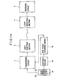
- Fig. 1 is a block diagram illustrating the construction of an embodiment of the present invention.
- reference numeral 1A indicates a counting means, consisting of one-bit or multiple-bit counter, for counting the number of transmission operations performed by pressing input keys and the like installed in a transmission circuit on a transmitting side
- reference numeral 1B indicates an end pulse changing means for changing a construction of end pulses in such a way that the construction may correspond 1 versus 1 to numeric values counted by the counting means lA.
- the end pulse changing means consists of a pulse number setting means for changing the number of pulses constructing the end pulse.
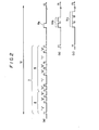
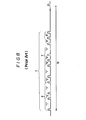
- Fig. 2 is a pulse waveform chart of a transmission signal illustrating a transmission code format of the digital remote control device according to the embodiment mentioned above.
- reference numerals 8 and 9 indicate a custom code and an instruction code respectively
- reference numeral 7 indicates a word of transmission codes consisting of the custom code 8 and the instruction code 9
- reference numerals lla, llb and llc indicate end pulses having information on the number of transmission operations respectively
- reference numeral 12 indicates a repetition period of the transmission code.
- a circuit illustrated in Fig. l(b) is used as the transmission circuit 1, in which the numeral 110 indicates a key matrix receiving key input corresponding to the keys 21, the numeral (120) indicates a key scan controlling section for performing a key scan to get signals corresponding the key input, the numeral (130) indicates a transmission controlling section receiving signals from the key scan controlling section (120) to send transmission codes to the light emitting section 3, the numeral (140) indicates a key input detecting section for detecting key input detecting signals, outputted from the matrix, every pressing the key, the numeral (150) indicates a counter, corresponding to the counting means l A in Fig.l(b), for counting output from the key input detecting section (140).
- the numeral 130a indicates a pulse number setting section for receiving count value from the counter to set the pulse number of the end pulse and then to insert the end pulse into transmission codes which corresponds to the end pulse changing means.
- the number of operations for re-pressing a key are counted by a one-bit counter or multiple-bit counter to form end pulses having the number of pulses corresponding 1 versus 1 to the numeric values thus counted, and the end pulses are transmitted after transmitting the custom code 8 and the instruction code 9.
- the counter counts the number of operations for pressing the key as the numeric values of 1 ⁇ 2 ⁇ 3 ⁇ 1 ⁇ 2 ⁇ ..., and the end pulses corresponding to such numeric values are transmitted in the form of end pulses 11a ⁇ llb - llc - 11a ⁇ 11b ⁇ ... as shown in Fig. 2.
- the custom code 8 On a receiving side, the custom code 8, the instruction code 9 and the end pulse lla or llb or llc corresponding to any of the numeric values are received and decoded; in case the custom code 8 agrees with a custom code allocated to the receiving side and a waveform (number of pulses) of the end pulse is different from that received previously, it is judged that the key was re-pressed, whereby the receiving side makes a control candidate execute the instruction. In case the waveform of the end pulse is the same as that received previously, it is judged that the key was not re-pressed, whereby the receiving side does not make the control candidate execute the instruction.
- words 7 1 ⁇ 7 7 meaning a selection key No. 1 and words 78 ⁇ 7 14 meaning a selection key No. 3 are transmitted in the same manner as the conventional system, but a numeric value of 1 is added to the words 7 1 ⁇ 7 7 and a numeric value of 2 is added to the words 7 8 ⁇ 7 14 .
- new numeric values advancing step by step for each time of pressing keys are added to words.
- numeric values which were added to 7 6 ⁇ 7 7 are the same as numeric values which were added to 7 1 ⁇ 7 3 , whereby the words 7 4 and 7 5 can be regarded as one and the same group, and the control section 23 does not execute one and the same processing as the omission of the words.
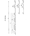
- the end pulse changing means 1B is constructed by a pulse width setting means for changing a pulse width constructing the end pulse.
- Fig. 4(a) shows the second embodiment, in which the numeral (lc) indicates the pulse width setting means, the pulse width setting means (lc) changes the pulse width of the end pulses (13a), (13b) and (13c) in accordance with the counting value supplied from the counting means (lA), as shown in Fig. 4(b).
- the pulse width setting means (lc) outputs end pulses (13a) of narrow width when counting value is 1, outputs end pulses (13b) of middle-sized width wider than that of the end pulses (13a) when counting value is 2 and outputs end pulses (13c) of broad width when counting value is 3, whereby the receiving side perceives counting value contained in the end pulse sent from the transmission side according to the width size of received pulses.
- the transmission circuit 1 concretely, used such a circuit that is shown in Fig. l(b) showing the first embodiment, but a pulse number setting section (130a) is replaced with a pulse width setting section in Fig. l(b).
- This pulse width setting section receives counting value from the counting means (lA) to set the pulse width of the end pulse and then inserts the end pulse with a set width into the transmission code.
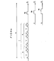
- the end pulse changing means 1B is constructed by a pulse recurrence interval setting means for changing pulse recurrence intervals between a plurality of pulses constructing end pulses.
- Fig. 5(a) shows the third embodiment, in which the numeral (lD) indicates the pulse interval setting means, the pulse interval setting means (lD) changes the pulse interval of the end pulses (14a) , (14b) and (14c) in accordance with the counting value supplied from the counting means (lA), as shown in Fig. 5(b)
- the pulse interval setting means (lD) outputs end pulses (14a) of short interval when counting value is 1, outputs end pulses (14b) of middle length interval longer than that of the end pulses (14a) when counting value is 2 and outputs end pulses (14c) of long interval when counting value is 3, whereby the receiving side perceives counting value contained in the end pulse sent from the transmission side according to the interval of received pulses.
- the transmission circuit 1 concretely, used such a circuit that is shown in Fig. l(b) showing the first embodiment, but a pulse number setting section (130a) is replaced with a pulse interval setting section in Fig. 1(b).
- This pulse interval setting section receives counting value from the counting means (lA) to set the pulse interval of the end pulse and then to insert the end pulse with a set interval into transmission code.
- examples were shown on the number of operations for transmission which were distinguished into three kinds of state.
- the number of operations can be set to any state but the state is in ⁇ -plurality of conditions.
- the instruction code and the end pulse were arranged on the positions apart somewhat from each other in terms of time, but they can be arranged on such positions that are near somewhat from each other in terms of time.
- the instruction was not executed on condition that the waveform (number of pulses) of end pulse received was the same as the waveform of end pulse received previously.
- this condition can be altered to the case where the instruction is not executed if the waveforms of both the instruction code and the end pulse received are equal to the waveforms of both the instruction code and the end pulse received previously.
- the digital remote control device is so constructed that the transmission is made with the addition of the information on the number of operations for transmission such as pressing keys and the like to the end pulse by means of changing the number of pulses constructing the end pulse on the transmission side. According, there are effects that the receiving side can read the above-mentioned information and can judge either the key is pressed consecutively or the key was re-pressed in case same instruction codes are received.
Landscapes
- Physics & Mathematics (AREA)
- General Physics & Mathematics (AREA)
- Selective Calling Equipment (AREA)
Applications Claiming Priority (6)
| Application Number | Priority Date | Filing Date | Title |
|---|---|---|---|
| JP61100087A JPS62256544A (ja) | 1986-04-30 | 1986-04-30 | デイジタルリモ−トコントロ−ル装置 |
| JP100089/86 | 1986-04-30 | ||
| JP100087/86 | 1986-04-30 | ||
| JP10008986A JPS62256545A (ja) | 1986-04-30 | 1986-04-30 | デイジタルリモ−トコントロ−ル装置 |
| JP102447/86 | 1986-05-01 | ||
| JP10244786A JPS62258532A (ja) | 1986-05-01 | 1986-05-01 | デイジタルリモ−トコントロ−ル装置 |
Publications (3)
| Publication Number | Publication Date |
|---|---|
| EP0247376A2 true EP0247376A2 (de) | 1987-12-02 |
| EP0247376A3 EP0247376A3 (de) | 1989-08-23 |
| EP0247376B1 EP0247376B1 (de) | 1996-11-13 |
Family
ID=27309139
Family Applications (1)
| Application Number | Title | Priority Date | Filing Date |
|---|---|---|---|
| EP87106217A Expired - Lifetime EP0247376B1 (de) | 1986-04-30 | 1987-04-29 | Digitales Fernsteuergerät |
Country Status (4)
| Country | Link |
|---|---|
| US (1) | US4814741A (de) |
| EP (1) | EP0247376B1 (de) |
| CN (1) | CN1005935B (de) |
| DE (1) | DE3751950T2 (de) |
Cited By (1)
| Publication number | Priority date | Publication date | Assignee | Title |
|---|---|---|---|---|
| FR2631143A1 (de) * | 1988-05-03 | 1989-11-10 | Thomson Consumer Electronics |
Families Citing this family (13)
| Publication number | Priority date | Publication date | Assignee | Title |
|---|---|---|---|---|
| US5239294A (en) * | 1989-07-12 | 1993-08-24 | Motorola, Inc. | Method and apparatus for authenication and protection of subscribers in telecommunication systems |
| IL94467A (en) * | 1989-07-12 | 1995-12-31 | Motorola Inc | Method for authentication and protection of subscribers in telecommunication |
| US5572193A (en) * | 1990-12-07 | 1996-11-05 | Motorola, Inc. | Method for authentication and protection of subscribers in telecommunications systems |
| US5594429A (en) * | 1993-10-27 | 1997-01-14 | Alps Electric Co., Ltd. | Transmission and reception system and signal generation method for same |
| CN1117338A (zh) * | 1993-11-24 | 1996-02-21 | 艾利森电话股份有限公司 | 模拟通信系统的验证 |
| JP3153084B2 (ja) * | 1994-11-15 | 2001-04-03 | エスエムケイ株式会社 | パルス変調方法 |
| US8272959B2 (en) * | 1997-11-14 | 2012-09-25 | Elottery, Inc. | Interactive computer gaming system with audio response |
| FR2801128A1 (fr) * | 1999-11-15 | 2001-05-18 | Prigent O Meara Erven | Systeme de commande a distance d'au moins un appareil electrique par l'intermediaire d'un interrupteur multifonctionnel |
| JP3070733U (ja) * | 2000-02-03 | 2000-08-15 | 船井電機株式会社 | リモコンキ―連続押し検出装置 |
| JP2002152852A (ja) * | 2000-11-08 | 2002-05-24 | Sony Corp | リモートコマンダー |
| JP2005504485A (ja) * | 2001-09-24 | 2005-02-10 | コーニンクレッカ フィリップス エレクトロニクス エヌ ヴィ | 送信信号中の連続的なスペースの最大数を減少させる符号化機能を有する赤外線通信システム |
| JP2005012508A (ja) * | 2003-06-19 | 2005-01-13 | Alpine Electronics Inc | リモコン誤動作防止装置、リモコンの誤動作防止機能を備えた電子機器およびリモコン送信機、リモコンの誤動作防止方法 |
| CN107742915B (zh) * | 2013-12-06 | 2021-02-19 | 深圳市大疆创新科技有限公司 | 电池以及具有该电池的飞行器 |
Family Cites Families (6)
| Publication number | Priority date | Publication date | Assignee | Title |
|---|---|---|---|---|
| DE2737467C2 (de) * | 1977-08-19 | 1982-05-06 | Deutsche Itt Industries Gmbh, 7800 Freiburg | Fernsteueranordnung |
| DE2809796A1 (de) * | 1978-03-07 | 1979-09-13 | Siemens Ag | Fernbedienungsanlage fuer ein elektrisches geraet |
| US4210777A (en) * | 1978-06-15 | 1980-07-01 | Frederick Electronics Corp. | Pseudo-transparent stop bit generator |
| JPS5949633A (ja) * | 1982-09-14 | 1984-03-22 | Toshiba Corp | リピ−ト制御方式 |
| FR2533380A1 (fr) * | 1982-09-17 | 1984-03-23 | Radiotechnique | Procede de telecommande, notamment pour televiseur |
| JPS60227547A (ja) * | 1984-04-25 | 1985-11-12 | Mitsubishi Electric Corp | デイジタルリモ−トコントロ−ル装置 |
-
1987
- 1987-02-26 CN CN87101588.9A patent/CN1005935B/zh not_active Expired
- 1987-04-28 US US07/043,608 patent/US4814741A/en not_active Expired - Fee Related
- 1987-04-29 DE DE3751950T patent/DE3751950T2/de not_active Expired - Fee Related
- 1987-04-29 EP EP87106217A patent/EP0247376B1/de not_active Expired - Lifetime
Cited By (1)
| Publication number | Priority date | Publication date | Assignee | Title |
|---|---|---|---|---|
| FR2631143A1 (de) * | 1988-05-03 | 1989-11-10 | Thomson Consumer Electronics |
Also Published As
| Publication number | Publication date |
|---|---|
| DE3751950T2 (de) | 1997-03-13 |
| CN1005935B (zh) | 1989-11-29 |
| CN87101588A (zh) | 1987-11-04 |
| EP0247376B1 (de) | 1996-11-13 |
| EP0247376A3 (de) | 1989-08-23 |
| US4814741A (en) | 1989-03-21 |
| DE3751950D1 (de) | 1996-12-19 |
Similar Documents
| Publication | Publication Date | Title |
|---|---|---|
| EP0247376A2 (de) | Digitales Fernsteuergerät | |
| US6424285B1 (en) | Communications system for remote control systems | |
| US5515051A (en) | Wireless signaling system | |
| US4833467A (en) | Data transmission system | |
| US4412218A (en) | Remote control signal transmitter capable of setting custom codes individually alloted to a plurality of controlled instruments | |
| EP0247883A2 (de) | Digitales Fernsteuerungsübertragungsgerät | |
| EP0162327A1 (de) | Digitales Fernsteuerverfahren | |
| KR970004188B1 (ko) | 영상신호 처리기의 자막표시 방법 및 장치 | |
| US4751574A (en) | Electronic apparatus control system | |
| EP0377335B1 (de) | Decodierung von biphasencodierten Daten | |
| GB1502862A (en) | Information transmission systems | |
| US7310117B2 (en) | Video signal format secondary-conversion method, time code signal transmission method, and time code transmitting apparatus | |
| US4389644A (en) | Asynchronous type multichannel signal processing system | |
| GB1579846A (en) | Remote control systems | |
| US7697605B2 (en) | Signal transmitting/receiving system and method, signal transmitting apparatus and method, signal processing apparatus and method, recording medium, and program for transmitting/receiving signals unaffected by other apparatuses | |
| US20020168029A1 (en) | Digital signal receiving apparatus | |
| EP0223311A2 (de) | Fernsteuersystem | |
| US6134248A (en) | Method for transmitting data with tolerance for superimposed data | |
| KR0176830B1 (ko) | 다수의 리모콘 신호 수신방법 | |
| JPH0511709B2 (de) | ||
| US5363439A (en) | DTMF signal receiving system | |
| JPH09130869A (ja) | リモートコントロールシステム | |
| JPS6342597A (ja) | デイジタルリモ−トコントロ−ル装置 | |
| JPH0670378A (ja) | 光ワイヤレスリモコン受信装置 | |
| JP2863676B2 (ja) | 巡回符号化装置 |
Legal Events
| Date | Code | Title | Description |
|---|---|---|---|
| PUAI | Public reference made under article 153(3) epc to a published international application that has entered the european phase |
Free format text: ORIGINAL CODE: 0009012 |
|
| AK | Designated contracting states |
Kind code of ref document: A2 Designated state(s): DE FR GB |
|
| PUAL | Search report despatched |
Free format text: ORIGINAL CODE: 0009013 |
|
| AK | Designated contracting states |
Kind code of ref document: A3 Designated state(s): DE FR GB |
|
| 17P | Request for examination filed |
Effective date: 19890919 |
|
| 17Q | First examination report despatched |
Effective date: 19910823 |
|
| GRAG | Despatch of communication of intention to grant |
Free format text: ORIGINAL CODE: EPIDOS AGRA |
|
| GRAH | Despatch of communication of intention to grant a patent |
Free format text: ORIGINAL CODE: EPIDOS IGRA |
|
| GRAH | Despatch of communication of intention to grant a patent |
Free format text: ORIGINAL CODE: EPIDOS IGRA |
|
| GRAA | (expected) grant |
Free format text: ORIGINAL CODE: 0009210 |
|
| AK | Designated contracting states |
Kind code of ref document: B1 Designated state(s): DE FR GB |
|
| REF | Corresponds to: |
Ref document number: 3751950 Country of ref document: DE Date of ref document: 19961219 |
|
| ET | Fr: translation filed | ||
| PLBE | No opposition filed within time limit |
Free format text: ORIGINAL CODE: 0009261 |
|
| STAA | Information on the status of an ep patent application or granted ep patent |
Free format text: STATUS: NO OPPOSITION FILED WITHIN TIME LIMIT |
|
| 26N | No opposition filed | ||
| PGFP | Annual fee paid to national office [announced via postgrant information from national office to epo] |
Ref country code: DE Payment date: 19980511 Year of fee payment: 12 |
|
| PG25 | Lapsed in a contracting state [announced via postgrant information from national office to epo] |
Ref country code: DE Free format text: LAPSE BECAUSE OF NON-PAYMENT OF DUE FEES Effective date: 20000201 |
|
| PGFP | Annual fee paid to national office [announced via postgrant information from national office to epo] |
Ref country code: FR Payment date: 20010409 Year of fee payment: 15 |
|
| PGFP | Annual fee paid to national office [announced via postgrant information from national office to epo] |
Ref country code: GB Payment date: 20010425 Year of fee payment: 15 |
|
| REG | Reference to a national code |
Ref country code: GB Ref legal event code: IF02 |
|
| PG25 | Lapsed in a contracting state [announced via postgrant information from national office to epo] |
Ref country code: GB Free format text: LAPSE BECAUSE OF NON-PAYMENT OF DUE FEES Effective date: 20020429 |
|
| GBPC | Gb: european patent ceased through non-payment of renewal fee |
Effective date: 20020429 |
|
| PG25 | Lapsed in a contracting state [announced via postgrant information from national office to epo] |
Ref country code: FR Free format text: LAPSE BECAUSE OF NON-PAYMENT OF DUE FEES Effective date: 20021231 |
|
| REG | Reference to a national code |
Ref country code: FR Ref legal event code: ST |