EP0247442A2 - Tambour portant les têtes magnétiques rotatives dans un appareil d'enregistrement et de reproduction - Google Patents
Tambour portant les têtes magnétiques rotatives dans un appareil d'enregistrement et de reproduction Download PDFInfo
- Publication number
- EP0247442A2 EP0247442A2 EP87106966A EP87106966A EP0247442A2 EP 0247442 A2 EP0247442 A2 EP 0247442A2 EP 87106966 A EP87106966 A EP 87106966A EP 87106966 A EP87106966 A EP 87106966A EP 0247442 A2 EP0247442 A2 EP 0247442A2
- Authority
- EP
- European Patent Office
- Prior art keywords
- tape
- head device
- fixed cylinder
- rotating
- magnetic
- Prior art date
- Legal status (The legal status is an assumption and is not a legal conclusion. Google has not performed a legal analysis and makes no representation as to the accuracy of the status listed.)
- Granted
Links
- 238000011068 loading method Methods 0.000 claims description 29
- 238000004804 winding Methods 0.000 claims description 23
- 230000007246 mechanism Effects 0.000 claims description 15
- 230000002093 peripheral effect Effects 0.000 claims description 6
- 230000005540 biological transmission Effects 0.000 claims description 2
- 230000008054 signal transmission Effects 0.000 abstract description 6
- 230000015556 catabolic process Effects 0.000 abstract description 4
- 238000006731 degradation reaction Methods 0.000 abstract description 4
- 238000004806 packaging method and process Methods 0.000 abstract description 3
- 238000005056 compaction Methods 0.000 abstract 1
- 230000000694 effects Effects 0.000 description 9
- 238000010276 construction Methods 0.000 description 6
- 230000036316 preload Effects 0.000 description 4
- 230000010485 coping Effects 0.000 description 3
- 239000000470 constituent Substances 0.000 description 2
- 230000007423 decrease Effects 0.000 description 2
- 238000009499 grossing Methods 0.000 description 2
- 239000000463 material Substances 0.000 description 2
- 238000000034 method Methods 0.000 description 2
- 238000000465 moulding Methods 0.000 description 2
- 125000006850 spacer group Chemical group 0.000 description 2
- 230000000087 stabilizing effect Effects 0.000 description 2
- 238000013459 approach Methods 0.000 description 1
- 230000003247 decreasing effect Effects 0.000 description 1
- 238000011161 development Methods 0.000 description 1
- 230000018109 developmental process Effects 0.000 description 1
- 238000010586 diagram Methods 0.000 description 1
- 230000003292 diminished effect Effects 0.000 description 1
- 230000003467 diminishing effect Effects 0.000 description 1
- 230000002349 favourable effect Effects 0.000 description 1
- 238000003754 machining Methods 0.000 description 1
- 230000000414 obstructive effect Effects 0.000 description 1
- 238000003825 pressing Methods 0.000 description 1
- 238000010791 quenching Methods 0.000 description 1
- 230000000171 quenching effect Effects 0.000 description 1
- 230000000630 rising effect Effects 0.000 description 1
Images


Classifications
-
- G—PHYSICS
- G11—INFORMATION STORAGE
- G11B—INFORMATION STORAGE BASED ON RELATIVE MOVEMENT BETWEEN RECORD CARRIER AND TRANSDUCER
- G11B5/00—Recording by magnetisation or demagnetisation of a record carrier; Reproducing by magnetic means; Record carriers therefor
- G11B5/48—Disposition or mounting of heads or head supports relative to record carriers ; arrangements of heads, e.g. for scanning the record carrier to increase the relative speed
- G11B5/52—Disposition or mounting of heads or head supports relative to record carriers ; arrangements of heads, e.g. for scanning the record carrier to increase the relative speed with simultaneous movement of head and record carrier, e.g. rotation of head
- G11B5/53—Disposition or mounting of heads on rotating support
-
- G—PHYSICS
- G11—INFORMATION STORAGE
- G11B—INFORMATION STORAGE BASED ON RELATIVE MOVEMENT BETWEEN RECORD CARRIER AND TRANSDUCER
- G11B15/00—Driving, starting or stopping record carriers of filamentary or web form; Driving both such record carriers and heads; Guiding such record carriers or containers therefor; Control thereof; Control of operating function
- G11B15/60—Guiding record carrier
- G11B15/61—Guiding record carrier on drum, e.g. drum containing rotating heads
- G11B15/615—Guiding record carrier on drum, e.g. drum containing rotating heads inside container
-
- G—PHYSICS
- G11—INFORMATION STORAGE
- G11B—INFORMATION STORAGE BASED ON RELATIVE MOVEMENT BETWEEN RECORD CARRIER AND TRANSDUCER
- G11B15/00—Driving, starting or stopping record carriers of filamentary or web form; Driving both such record carriers and heads; Guiding such record carriers or containers therefor; Control thereof; Control of operating function
- G11B15/60—Guiding record carrier
- G11B15/66—Threading; Loading; Automatic self-loading
- G11B15/665—Threading; Loading; Automatic self-loading by extracting loop of record carrier from container
- G11B15/6653—Threading; Loading; Automatic self-loading by extracting loop of record carrier from container to pull the record carrier against drum
Definitions
- the prior art has been problematic in the points of machining and assembling costs for the reasons that the head rotating member needs to be formed with the spiral grooves of complicated shape and that the gaps between the grooves and the fixed cylinders need to be controlled to predetermined narrow intervals. Moreover, since the air is blown out uniformly over the whole outer peripheries of the cylinders, the air layer becomes thicker at the start part of tape winding where the tape exhibits a low tension. As a result, an ununiform air film is formed, and nonuniformity in the magnetic contact between each rotating head and the tape arises to cause nonuniformity in the physical contact of the two. This has posed the problem that degradation in the contact between the tape and the head, namely, the head-to-tape contact is prone to be incurred.
- the reasons why the subchassis is moved after the loading of the group of tape guides in predetermined amounts as stated above, are to define within the opening 8 a space into which the rotating head device 2 gets and to prevent the slack of the tape with the subchassis checked from moving at the time of the completion of the unloading.
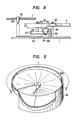
- Fig. 7 is a plan view showing the basic configuration of the subchassis 7.
- Numeral 51 designates a delivery reel bed which engages the delivery reel 4, and numeral 52 a take-up reel bed which engages the take-up reel 5.
- the cassette 6 when the cassette 6 is placed on the subchassis 7, it is positioned and held by positioning pins 53a, 53b and leveling pins 54a, 54b.
- three slots 50a, 50b and 50c are provided at end parts of the subchassis 7, and this subchassis is so supported as to be slidable in the directions of the slots 50a, 50b and 50c by means of guide pins 49a, 49b and 49c disposed on the main chassis 1, respectively.
- a cam groove 55 is a guide groove for driving the subchassis 7, and the driving method will be described with reference to Fig. 8.
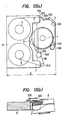
- Fig. 11(a) and Fig. 11(b) are conceptual diagrams for elucidating the effect according to the present invention, and the former illustrates the prior art, while the latter illustrates the present invention.
- Fig. 11(a) with the prior art, especially in the tape winding end part of high tape tension, air films are difficult to be formed between the tape 3 and the respective cylinders 34, 35, and the tape 3 comes into touch with the end-parts of the upper fixed cylinder 35 and the lower fixed cylinder 34.
- desired air layers can be formed between the tape and the cylinders even at the tape winding end part.
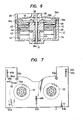
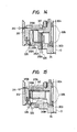
- the rotary disc 307 is fixed to the upper part of the rotary member 304 by bolts 71, the plurality of head bases 310 are fixed to the upper surface of the rotary disc 307 by bolts 72, and the magnetic head 309 protruding out beyond the tape traveling plane 308 are carried on the head bases 310.
- the flat FG coil 315 Carried on the lower surface of the flat portion of the stator base 313 parallel to the rotary disc 307 is the flat FG coil 315, in opposition to which the flat FG magnet 316 is arranged. More specifically, the FG magnet 316 is carried on the upper surface of the flat magnet holder 317, the flat motor magnet 318 is carried on the lower surface of the magnet holder 317, and the flat motor coil 319 is carried on the inside bottom of the lower fixed cylinder 34 in opposition to the motor magnet 318.
- a motor rotor unit is constructed of the FG magnet 316, the magnet holder 317, the motor magnet 318, and the motor rotor base 320 fixed to the magnet holder 317, and it is fixed to the rotary member 304 by screws.
- the radial vibrations of the motor magnet 318 and the FG magnet 316 with respect to the axis of rotation of the rotary member 304 can be adjusted.
- rotating magnetic heads capable of coping with multi-channeling can be realized, and when the device is installed on a magnetic recording and reproducing apparatus', it is permitted to overlap a tape cassette, and the rotating head device which can realize the magnetic recording and reproducing apparatus of small horizontal area can be provided.
Landscapes
- Recording Or Reproducing By Magnetic Means (AREA)
- Transmission And Conversion Of Sensor Element Output (AREA)
Applications Claiming Priority (4)
| Application Number | Priority Date | Filing Date | Title |
|---|---|---|---|
| JP61120249A JP2606822B2 (ja) | 1986-05-27 | 1986-05-27 | 磁気記録再生装置 |
| JP120249/86 | 1986-05-27 | ||
| JP210659/86 | 1986-09-09 | ||
| JP61210659A JPS6366752A (ja) | 1986-09-09 | 1986-09-09 | 回転磁気ヘツド装置 |
Publications (3)
| Publication Number | Publication Date |
|---|---|
| EP0247442A2 true EP0247442A2 (fr) | 1987-12-02 |
| EP0247442A3 EP0247442A3 (en) | 1989-02-22 |
| EP0247442B1 EP0247442B1 (fr) | 1993-02-24 |
Family
ID=26457866
Family Applications (1)
| Application Number | Title | Priority Date | Filing Date |
|---|---|---|---|
| EP87106966A Expired - Lifetime EP0247442B1 (fr) | 1986-05-27 | 1987-05-14 | Tambour portant les têtes magnétiques rotatives dans un appareil d'enregistrement et de reproduction |
Country Status (4)
| Country | Link |
|---|---|
| US (1) | US4814910A (fr) |
| EP (1) | EP0247442B1 (fr) |
| KR (1) | KR900007481B1 (fr) |
| DE (1) | DE3784269T2 (fr) |
Cited By (4)
| Publication number | Priority date | Publication date | Assignee | Title |
|---|---|---|---|---|
| US4949203A (en) * | 1987-03-11 | 1990-08-14 | Pioneer Electronic Corporation | Tape recorder having an improved cassette mounting device |
| EP0361275A3 (fr) * | 1988-09-30 | 1991-02-27 | Hitachi, Ltd. | Mécanisme de chargement de bande pour dispositif magnétique d'enregistrement et de reproduction |
| EP0422670A3 (en) * | 1989-10-13 | 1992-02-26 | Matsushita Electric Industrial Co., Ltd. | Tape loading device of a video tape recorder |
| EP0531751A3 (fr) * | 1991-09-13 | 1993-04-28 | Hitachi, Ltd. | Dispositif d'enregistrement et de reproduction magnétique |
Families Citing this family (9)
| Publication number | Priority date | Publication date | Assignee | Title |
|---|---|---|---|---|
| US5025332A (en) * | 1988-08-30 | 1991-06-18 | Sanyo Electric Co., Ltd. | Recording-reproducing system having movable reel chassis |
| DE3836621A1 (de) * | 1988-10-27 | 1990-05-03 | Thomson Brandt Gmbh | Fuehrung fuer ein magnetband |
| JPH02210647A (ja) * | 1989-02-10 | 1990-08-22 | Hitachi Ltd | 磁気記録再生装置 |
| KR930006211Y1 (ko) * | 1990-07-31 | 1993-09-15 | 주식회사 금성사 | 자기기록장치의 일체형 테이프 이송 가이드장치 |
| JP2664281B2 (ja) * | 1990-11-09 | 1997-10-15 | 株式会社日立製作所 | 磁気記録再生装置 |
| JPH0528600A (ja) * | 1991-07-18 | 1993-02-05 | Sony Corp | 回転ヘツドドラム装置及び該装置を用いる磁気記録再生装置 |
| US5430586A (en) * | 1992-08-03 | 1995-07-04 | Koo; Kah O. | Tape extractor and pad lifter for extracting tape from a cassette center well, and related method |
| KR970050266A (ko) * | 1995-12-26 | 1997-07-29 | 배순훈 | 디지탈 브이시알용 헤드드럼 조립체 |
| US20050244167A1 (en) * | 2004-04-29 | 2005-11-03 | Liew Sanyuan | Signal-to-noise ratio (SNR) value characterization in a data recovery channel |
Family Cites Families (6)
| Publication number | Priority date | Publication date | Assignee | Title |
|---|---|---|---|---|
| GB1249179A (en) * | 1968-11-09 | 1971-10-06 | Sony Corp | Magnetic tape recording and/or reproducing apparatus |
| US4025959A (en) * | 1971-04-05 | 1977-05-24 | Rca Corporation | Recorder-reproducer system |
| JPS58148729U (ja) * | 1982-03-31 | 1983-10-06 | 株式会社日立製作所 | 回転磁気ヘツドドラム |
| US4595961A (en) * | 1982-12-21 | 1986-06-17 | Matsushita Electric Industrial Co., Ltd. | Helical scan type tape recording reproducing apparatus having a part-cylindrical drum |
| JPS59171070A (ja) * | 1983-03-18 | 1984-09-27 | Matsushita Electric Ind Co Ltd | 記録再生装置 |
| NL8403472A (nl) * | 1984-11-14 | 1986-06-02 | Philips Nv | Magneetbandapparaat. |
-
1987
- 1987-05-14 DE DE8787106966T patent/DE3784269T2/de not_active Expired - Fee Related
- 1987-05-14 EP EP87106966A patent/EP0247442B1/fr not_active Expired - Lifetime
- 1987-05-23 KR KR8705120A patent/KR900007481B1/ko not_active Expired
- 1987-05-27 US US07/054,864 patent/US4814910A/en not_active Expired - Lifetime
Cited By (5)
| Publication number | Priority date | Publication date | Assignee | Title |
|---|---|---|---|---|
| US4949203A (en) * | 1987-03-11 | 1990-08-14 | Pioneer Electronic Corporation | Tape recorder having an improved cassette mounting device |
| EP0361275A3 (fr) * | 1988-09-30 | 1991-02-27 | Hitachi, Ltd. | Mécanisme de chargement de bande pour dispositif magnétique d'enregistrement et de reproduction |
| EP0422670A3 (en) * | 1989-10-13 | 1992-02-26 | Matsushita Electric Industrial Co., Ltd. | Tape loading device of a video tape recorder |
| US5204791A (en) * | 1989-10-13 | 1993-04-20 | Matsushita Electric Industrial Co., Ltd. | Tape loading device of a video tape recorder having a linkage driven inclined auxiliary tape guide member |
| EP0531751A3 (fr) * | 1991-09-13 | 1993-04-28 | Hitachi, Ltd. | Dispositif d'enregistrement et de reproduction magnétique |
Also Published As
| Publication number | Publication date |
|---|---|
| EP0247442A3 (en) | 1989-02-22 |
| KR900007481B1 (en) | 1990-10-10 |
| DE3784269D1 (de) | 1993-04-01 |
| KR870011576A (ko) | 1987-12-24 |
| DE3784269T2 (de) | 1993-06-09 |
| US4814910A (en) | 1989-03-21 |
| EP0247442B1 (fr) | 1993-02-24 |
Similar Documents
| Publication | Publication Date | Title |
|---|---|---|
| EP0247442B1 (fr) | Tambour portant les têtes magnétiques rotatives dans un appareil d'enregistrement et de reproduction | |
| EP0273620B1 (fr) | Dispositif de tête magnétique rotative | |
| JPH02281408A (ja) | 可搬式vtr | |
| JP2606822B2 (ja) | 磁気記録再生装置 | |
| US5016125A (en) | Tape loading mechanism for a magnetic recording/reproducing apparatus | |
| JP2580578B2 (ja) | 磁気記録再生装置 | |
| JP2927060B2 (ja) | 磁気記録再生装置 | |
| US5627705A (en) | Recording and/or reproducing apparatus having rotary drum unit | |
| JPH0450666B2 (fr) | ||
| JP2693049B2 (ja) | 記録または再生装置 | |
| JP3146613B2 (ja) | 磁気記録再生装置 | |
| JP2848008B2 (ja) | 磁気記録再生装置 | |
| JP2574760B2 (ja) | テ−プ装架機構 | |
| JPS6117257A (ja) | 磁気記録再生装置 | |
| JP3461223B2 (ja) | 回転ドラム装置及び記録又は再生装置 | |
| JPH0378151A (ja) | 磁気記録再生装置のテープガイド機構 | |
| JP2570193B2 (ja) | テープレコーダー | |
| JP3613844B2 (ja) | 磁気記録再生装置 | |
| JP3168149B2 (ja) | 磁気記録再生装置 | |
| JPS593704A (ja) | 磁気記録再生装置 | |
| JPH0812730B2 (ja) | 磁気記録再生装置 | |
| JPS6360457B2 (fr) | ||
| JPS6224462A (ja) | 磁気記録再生装置 | |
| JPS583305B2 (ja) | ジキキロクサイセイソウチ | |
| JPH03152757A (ja) | 磁気記録再生装置 |
Legal Events
| Date | Code | Title | Description |
|---|---|---|---|
| PUAI | Public reference made under article 153(3) epc to a published international application that has entered the european phase |
Free format text: ORIGINAL CODE: 0009012 |
|
| 17P | Request for examination filed |
Effective date: 19870514 |
|
| AK | Designated contracting states |
Kind code of ref document: A2 Designated state(s): DE FR GB |
|
| PUAL | Search report despatched |
Free format text: ORIGINAL CODE: 0009013 |
|
| AK | Designated contracting states |
Kind code of ref document: A3 Designated state(s): DE FR GB |
|
| 17Q | First examination report despatched |
Effective date: 19901120 |
|
| GRAA | (expected) grant |
Free format text: ORIGINAL CODE: 0009210 |
|
| AK | Designated contracting states |
Kind code of ref document: B1 Designated state(s): DE FR GB |
|
| REF | Corresponds to: |
Ref document number: 3784269 Country of ref document: DE Date of ref document: 19930401 |
|
| ET | Fr: translation filed | ||
| PLBE | No opposition filed within time limit |
Free format text: ORIGINAL CODE: 0009261 |
|
| STAA | Information on the status of an ep patent application or granted ep patent |
Free format text: STATUS: NO OPPOSITION FILED WITHIN TIME LIMIT |
|
| 26N | No opposition filed | ||
| PGFP | Annual fee paid to national office [announced via postgrant information from national office to epo] |
Ref country code: FR Payment date: 19980415 Year of fee payment: 12 |
|
| PGFP | Annual fee paid to national office [announced via postgrant information from national office to epo] |
Ref country code: GB Payment date: 19980501 Year of fee payment: 12 |
|
| PGFP | Annual fee paid to national office [announced via postgrant information from national office to epo] |
Ref country code: DE Payment date: 19980629 Year of fee payment: 12 |
|
| PG25 | Lapsed in a contracting state [announced via postgrant information from national office to epo] |
Ref country code: GB Free format text: LAPSE BECAUSE OF NON-PAYMENT OF DUE FEES Effective date: 19990514 |
|
| GBPC | Gb: european patent ceased through non-payment of renewal fee |
Effective date: 19990514 |
|
| PG25 | Lapsed in a contracting state [announced via postgrant information from national office to epo] |
Ref country code: FR Free format text: LAPSE BECAUSE OF NON-PAYMENT OF DUE FEES Effective date: 20000131 |
|
| PG25 | Lapsed in a contracting state [announced via postgrant information from national office to epo] |
Ref country code: DE Free format text: LAPSE BECAUSE OF NON-PAYMENT OF DUE FEES Effective date: 20000301 |
|
| REG | Reference to a national code |
Ref country code: FR Ref legal event code: ST |