EP0247498A1 - Mechanische Feststellvorrichtung - Google Patents
Mechanische Feststellvorrichtung Download PDFInfo
- Publication number
- EP0247498A1 EP0247498A1 EP87107261A EP87107261A EP0247498A1 EP 0247498 A1 EP0247498 A1 EP 0247498A1 EP 87107261 A EP87107261 A EP 87107261A EP 87107261 A EP87107261 A EP 87107261A EP 0247498 A1 EP0247498 A1 EP 0247498A1
- Authority
- EP
- European Patent Office
- Prior art keywords
- spool
- groove
- spring
- engaging
- resilient element
- Prior art date
- Legal status (The legal status is an assumption and is not a legal conclusion. Google has not performed a legal analysis and makes no representation as to the accuracy of the status listed.)
- Withdrawn
Links
- 230000033001 locomotion Effects 0.000 claims description 9
- 238000010276 construction Methods 0.000 description 6
- 230000000875 corresponding effect Effects 0.000 description 6
- 230000007935 neutral effect Effects 0.000 description 3
- 238000004519 manufacturing process Methods 0.000 description 2
- 230000001276 controlling effect Effects 0.000 description 1
- 230000001419 dependent effect Effects 0.000 description 1
- 230000003455 independent Effects 0.000 description 1
- 238000000034 method Methods 0.000 description 1
- 230000004048 modification Effects 0.000 description 1
- 238000012986 modification Methods 0.000 description 1
Images



Classifications
-
- G—PHYSICS
- G05—CONTROLLING; REGULATING
- G05G—CONTROL DEVICES OR SYSTEMS INSOFAR AS CHARACTERISED BY MECHANICAL FEATURES ONLY
- G05G5/00—Means for preventing, limiting or returning the movements of parts of a control mechanism, e.g. locking controlling member
- G05G5/06—Means for preventing, limiting or returning the movements of parts of a control mechanism, e.g. locking controlling member for holding members in one or a limited number of definite positions only
-
- F—MECHANICAL ENGINEERING; LIGHTING; HEATING; WEAPONS; BLASTING
- F16—ENGINEERING ELEMENTS AND UNITS; GENERAL MEASURES FOR PRODUCING AND MAINTAINING EFFECTIVE FUNCTIONING OF MACHINES OR INSTALLATIONS; THERMAL INSULATION IN GENERAL
- F16K—VALVES; TAPS; COCKS; ACTUATING-FLOATS; DEVICES FOR VENTING OR AERATING
- F16K31/00—Actuating devices; Operating means; Releasing devices
- F16K31/44—Mechanical actuating means
- F16K31/56—Mechanical actuating means without stable intermediate position, e.g. with snap action
-
- Y—GENERAL TAGGING OF NEW TECHNOLOGICAL DEVELOPMENTS; GENERAL TAGGING OF CROSS-SECTIONAL TECHNOLOGIES SPANNING OVER SEVERAL SECTIONS OF THE IPC; TECHNICAL SUBJECTS COVERED BY FORMER USPC CROSS-REFERENCE ART COLLECTIONS [XRACs] AND DIGESTS
- Y10—TECHNICAL SUBJECTS COVERED BY FORMER USPC
- Y10T—TECHNICAL SUBJECTS COVERED BY FORMER US CLASSIFICATION
- Y10T74/00—Machine element or mechanism
- Y10T74/20—Control lever and linkage systems
- Y10T74/20576—Elements
- Y10T74/20636—Detents
- Y10T74/2066—Friction
Definitions
- the present invention relates to a mechanical detent for holding a valve spool in a predetermined position along its longitudinal axis.
- a detent One application of a detent is to hold a spool that is spring-centered, i.e., the spool returns automatically to a neutral position when the detent is disengaged. Another application of a detent is to hold a spool that is not spring-centered, i.e., the spool is manually moved to all positions including neutral.
- a mechanical detent may also be used for a "feel" position. To move the spool past a feel position requires the operator to exert a higher force, indicating that a particular stage of the spool stroke has been reached or passed through. However, the spool is not physically held in this position.
- a valve spool in a predetermined position by means of a mechanical detent has been attempted in many forms.
- Various forms of the detent include spring-loaded radial detents and C-shaped spring detents which surround the circumference of the valve spool. All of the above detents engage a groove or a step on the periphery of the valve spool.
- the spring-loaded radial detents engage a groove on the spool stem, producing a radial force at a single point of contact.
- Some problems with the spring-loaded radial detents are that they require a number of parts, take up a large amount of space in the housing of the valve spool, and are costly both in part costs and assembly time.
- the ball construction in the case of a ball-type radial detent, the ball construction must display a radius approximately two or more times greater than the depth of the groove in order to provide a means for effectively moving the ball out of the groove.
- the deeper the groove is made the larger the ball size must be. In trying to keep the ball size within an acceptable size range, while maintaining an acceptable groove depth, this required ratio between the ball and the groove results in a relatively shallow groove and a relatively large ball.
- this construction creates the need for heavy loading of balls by spring(s) in order to maintain the ball in the groove. Additionally, where the ball size must be at least two times the groove depth, the only way to minimize the overall size of the valve structure is to have close toleranced housing valve spool and engaging parts. Such close toleranced parts increase the overall cost of the valve structure.
- the C-shaped spring surrounds the circumference of the valve spool and radially extends around the grooveless surface of the valve spool.
- the C-shaped spring provides essentially continuous contact around the surface of the spool.
- the C-shaped spring must have a relatively large cross-sectional diameter with respect to the groove depth since it must extend well beyond the surface of the spool to be effectively moved out of the groove. This required dimension of the groove engaging element creates the need for a relatively shallow groove to keep the C-ring size in an acceptable range and a corresponding heavy loading to maintain the element in the groove.
- the structure of the C-shaped spring and the ball-type detent also requires large spring size in order to have as low a rated spring (load/deflection) as possible.
- a low rated spring is necessary in order to have a maximum groove depth. Having a groove that is as deep as possible is desireable for manufacturing and tolerancing purposes.
- a low rated spring is necessary in the case of a maximum groove depth in order to move the element out of the groove. Without a low rated spring, a large load is required to move the element out of the groove.
- due to the construction of the above-mentioned detents it is necessary to further increase the overall size of the spring to achieve a low rated spring.
- the overall diameter D of the spring (the full length of the "C") must be large with respect to the diameter d of the wire of the spring, further increasing the size of the structure.
- the rate of the C-shaped spring is related to the ratio d/D. The lower this ratio, the lower the spring rate. Since the diameter d of the wire must be at least two times the groove depth, the numerator of this rate, d, has a somewhat "fixed" minimum value. Thus, to have a lower spring rate, the denominator, D, the overall size of the spring, must be large. Where a spool size is predetermined, modification of the spool may be necessary in order to accommodate a large, low rate spring.
- the spring rate is also related to the ratio d/D.
- the length of the spring, D must be large, making the overall size of the spring very large.
- the length of the spring especially affects the size of the total valve structure due to its orientation.
- the coil spring is positioned radially outward from the ball.
- each increase in spring length further extends the radial distance between the spool and the housing required to accommodate the ball and spring.
- the load angle is defined as the angle between a horizontal axis through the groove engaging element and the axis traveling through the point of contact of the engaging element against the side wall of the groove and the center of the element.
- the load angle is equal to the angle of the side wall of the groove, or the groove angle. Due to the large load required in these types of detents, as well as the correspondingly high loading rates involved, these systems usually employ an edge contact point, whereby the outer diameter edge of the spool stem at the point where the groove begins contacts the wire or ball. This construction provides poor load angle control and high point contact stresses.
- a mechanical detent for engaging a valve spool characterized by a spool having at least one cir cumferential groove, said circumferential groove having a depth and a predetermined position on said spool, a linear resilient element positioned transverse to the surface of said spool for engaging said groove, and an engaging element for engaging said linear resilient element during movement of said spool and disengaging said resilient element from said groove.
- a mechanical detent for engaging a valve spool characterized by a spool having at least one circumferential groove, said circumferential groove having a depth and a predetermined position on said spool, a resilient element for engaging said groove and having a width and a length, said width being positioned along the depth of the groove and the length being positioned transverse to the surface of said spool, said length forming extensions extending a distance at least equal to or greater than the cross-sectional diameter of the resilient element, and an engaging element for engaging said extensions during movement of said spool and disengaging said resilient means from said groove.
- a mechanical detent for engaging a valve spool characterized by a spool having at least one circumferential groove, said circumferential groove having a depth and a predetermined position on said spool, a resilient element for engaging said groove having a width and a length, said width being positioned along the depth of the groove and the length being positioned transverse to the surface of said spool, said length forming extensions, and an engaging element for engaging said extensions during movement of said spool and disengaging said resilient element from said groove, said resilient element having a cross-sectional radius that is indepen dent of the depth of the circumferential groove.
- the detent has a linear element spring having extensions which extend a sufficient distance beyond the surface of a spool to be engageable with the engaging element which moves the spring out of circumferential grooves on the spool.
- the wire diameter of the spring is not critical, and may, for example, be reduced since the groove engaging portion of the wire is not the primary contact surface used to force the spring out of the groove.
- the spring may be formed from a single wire having three or more linear segments interconnected at elbows. Alternatively, one or more linear springs may be positioned by a retainer.
- the extensions should extend a distance at least twice the diameter of the spring wire. Since the radius of the spring wire is not dependent on the particular desired groove depth, the radius of the spring wire can be greater than, equal to or less than the depth of the circumferential groove. Additionally, since there is no minimum required value for the spring wire in relation to the groove depth, a low rate spring may be designed without requiring a large spring size. Also, since the spring wire need not be at least two times the size of the groove depth, the point of contact between the groove engaging element and the side wall of the groove is below the edge point where the groove meets the outer diameter of the spool.
- the detent mechanism is contemplated for use in a valve assembly.
- the valve assembly is comprised of a valve housing ll having an internal cylindrical bore l2.
- a valve spool with spool stem l3 is positioned and is movable within the bore l2 along the longitudinal axis of the spool stem l3.
- the spool l3 may be moved manually or otherwise in either one direction or both directions within the bore l2 to define a plurality of operational positions of the spool. While a three position valve usually includes forward, reverse and neutral positions, a four position valve may additionally include a float position. Forward and reverse are only relative and in some applications represent raise and lower. These are just examples.
- the spool stem l3 has at least one circumferential groove l4 and/or step or ramp 24 spaced along its length. Depending on whether the contour of the spool is grooved or stepped, a position along the stem l3 will represent either a "stop" position (l4) or a "feel” position (24), respectively.
- the detent mechanism in the valve housing is comprised of at least one linear element spring positioned transverse to the axis of motion of the spool stem l3.
- the linear spring 35 has three linear sides or elements 36, 37 and 38 formed from a single wire spring.
- This triangle-shaped spring, open-ended at one point of the triangle comprises two linear sides or elements 36 and 38 having one open end and one closed end and one side 37 having two closed ends.
- Each of the linear sides of the spring is positioned transverse to the surface of the spool stem l3, creating a tangent to the point of contact between the spring elements 36, 37, 38 and the spool stem l3.
- the triangle-shaped spring is biased against the surface of the spool stem at all times, and thus, holds itself in place.
- An engaging element 28 is formed as part of the detent housing l8 and maintains the spring in an essentially radial position with respect to the surface of the spool stem l3 during operation.
- the engaging element 28 is formed as two annular plates around the spool stem l3 as shown in Figures l and 2.
- the shoulder 30 of the engaging element 28 defines an axial space having radial width w r between the engaging element 28 and the non-grooved outer surface of the spool l3.
- a radial width w r is defined by the distance between the engaging element 28 and the bottom of the groove l4 in the spool l3.
- the inner surface 29 of the two engaging plates 28 defines a radial space having an axial width w a in which the elbow shaped extensions of the triangular shaped spring are maintained.
- the axial width w a of the radial space is slightly greater than the diameter d2 of the spring to minimize axial movement with respect to the spool.
- the radial width w r of the axial space may be greater than, equal to or less than the diameter d2 of the spring since this parameter is not critical and is not dictated by any constraints in the design.
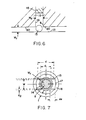
- the above configuration, shown in Figure 2 and 6, minimizes the axial deflection of the spring elements.
- the spool stem diameter is generally dictated by various existing parts to be attached to the spool stem.
- A, B and C are various parts which are incorporated in the valve spool assembly.
- the clearance w r between the spool and housing is generally chosen to be as small as possible without having to redesign or require special tolerances of the other existing parts. According to an embodiment of the invention, this clearance w r is approximately 0.0l5 to 0.020.
- angles created by the elbow-shaped extensions must be an angle which will provide as equal a load as possible at the three points of contact to ensure that the clip will snap completely into the groove upon engagement.
- this angle ⁇ (phi) is 50° to 60°.
- a second consideration is the requisite support length of the spring member which is positioned transverse to the spool.
- the support length is defined as the distance the linear wire element extends from the inner diameter of the retainer.
- the relationship between the chosen support length S and the wire diameter d2 must be such that there is minimal axial deflection of the linear detent sections as the spool moves.
- practical supports lengths s a through s b are determined. Using these practical support lengths s a through s b , the axial holding load which will be applied to the wire, and considering a minimal axial deflection of the spring wire, a range of possible wire diameters d a through d b may be determined. Each of these diameters will provide a different loading rate (load vs. deflection).
- a third consideration in choosing the dimensions of the detent is that it is preferable to have as low rated a spring as possible.
- the spring rate corresponds to the relationship between the diameter of the spring wire vs. spring size (d/D).
- the wire diameter must be relatively high.
- the spring size D must be relatively large in order to get a low spring rate.
- d is not as limited to large sizes.
- the size of the spring need not be as large in order to obtain a low spring rate. In this way, low spring rates are available in the invention without requiring a large overall package.
- the triangle-shaped spring forms elbow-shaped extensions which extend a distance d e from the surface of the spool.
- the length d e of these extensions is at least equal to or greater than diameter d2 of the wire of the triangle-shaped spring.
- This configuration is advantageous in that a relatively small diameter spring may be used, since engaging element 28 may engage the extensions d e of the spring to displace the spring as the spool moves, instead of the portion of the spring extending radially out of the groove l4, as is the case with radial-type detents and C-shaped spring detents.
- the extensions permit the engaging element 28 to easily move the spring out of the groove.
- a relatively small diameter spring can be used which sits deeply into the groove. This configuration results in the detent having good "feel" characteristics since the smaller spring having extensions will travel a greater radial distance in and out of the groove, and thus, more positively engage and disengage the groove.
- the compact detent may be used at portions of the valve assembly having a very small diameter. Since the extension extends beyond the spool l3 and engages the engaging element 28 outside the axial space, the radial width w r of the axial space is less critical and may be designed to be greater than, equal to or less than the diameter d2 of the wire. Similarly, the radius r of the wire may be greater than, equal to or less than the depth g of the groove l4. A particular figure is not dictated by any other constraints of the design.
- the prior art specifically the C-ring and the ball-type detents, do not have the same advantageous characteristic.
- a C-ring and a ball type detent must be engaged at a point below their central plane to be moved out of the groove effectively.
- they must be designed to have a radius at least two times the depth of the groove, to provide a means for being lifted out of the groove.
- Such a construction requires a relatively shallow groove with respect to the size of the C-ring or ball.
- the C-ring and ball do not sit as deeply in the groove and therefore do not provide an effective "feel" characteristic.
- the size of the C-ring or ball must be increased to maintain its ability to disengage.
- a lower spring rate will be required as the groove becomes deeper, corresponding to an even larger size of the C-ring or coil spring used with the ball type detent.
- the spring exhibits "bowing" characteristics as it moves out of the step or groove.
- the open-ended sides 36 and 38 deflect outwardly and upwardly to accommodate the larger diameter of the spool as the spring moves out of the step or groove l4.
- This flexibility due to the open-end at one point of the triangle-shaped spring, results in improved rate control characteristics of the detent mechanism (controlling the load with respect to deflection of the spring).
- the flexibility of the triangle-shaped spring allows the use of a less expensive, smaller diameter wire.
- the groove can have a deeper design resulting in a better "feel" characteristic.
- the C-ring does not have as effective a "feel" characteristic. Since it does not deflect as easily, requiring a large load per deflection, it is designed for use with relatively shallow grooves. A deeper groove with a corresponding better "feel” characteristic is inefficient to design since an even larger load would be required to move the C-ring out of the groove. Since the groove must be relatively shallow, the load that the C-ring must exert to remain in the groove is relatively large.
- the linear spring has four linear sides or elements 46, 47, 48 and 49 and is formed from a single wire.
- This rectangular-shaped spring, open-ended at one point of the rectangle comprises two linear elements 46 and 49 having an open end and a closed end and two linear elements 47 and 48 having two closed ends.
- the elements are positioned transverse to the spool l3 and are prevented from axially deflecting by means of an engaging element 28 as shown in Figure 2.
- advantageous features exist with respect to the elbow-shaped extensions and the compactness of the design.
- the linear spring is comprised of one (not shown), two ( Figure 7) or three (not shown) straight wire springs l5 positioned transverse to and extending beyond the spool stem l3.
- the springs are held in place by a retainer l6 which surrounds the spool stem l3.
- the retainer l6 is an annular plate that is round inside and outside for ease of manufacturing.
- the inner circumference of the retainer has two key-type through-slots l7 which are l80° apart.
- the straight wire springs l5 are maintained in position against the surface of the spool by means of the key slots as shown in Figure 7.
- the detent mechanism is held in a particular position along the path of travel of the spool stem l3 by the detent housing l8.
- the detent housing l8 is located adjacent to the retainer l6.
- the shoulder 20 of the detent housing l8 defines an axial space having radial width w r between the housing and the spool.
- the shoulder l9 defines a radial space having an axial width w a into which the spring can deflect.
- the axial width w a of the radial space is greater than the diameter d2 of the spring, and the radial width w r of the axial space may be greater than, equal to or less than the diameter d2 of the spring, so that the spring can deflect radially, with minimum axial movement.
- the above configuration, shown in Figure 6, limits axial deflection of the straight wire springs.
- the length d e of the extensions should be at least equal to or greater than the diameter d2 of the wire l5.
- the radius r of the wire l5 may be equal to, greater than or less than the depth g of the groove l4 since a particular radius is not required for engagement and disengagement purposes.
- the thin plate retainer l6 has a thickness corresponding to the axial width w a of the detent housing l8 which is slightly larger than the diameter of the spring wire d2. This configuration prevents the spring wire from being clamped by the retainer housing l8, which would minimize its linear looseness.
- the distance between the two corresponding key-type slots which retain the springs and the inner diameter of retainer forms the spring support distance d.
- the linear spring l5; 35; 45 travels along the surface of the spool stem l3 in a direction transverse to the longitudinal axis of the spool stem l3.
- the spring l5; 35; 45 is biased against the surface of the spool stem l3 in such a way that when the groove l4 on the spool stem l3 passes the spring l5; 35; 45, the spring engages the groove l4.
- the spring l5; 35; 45 has extensions d e which are engageable by a detent housing l8 or engaging element 28 for moving the spring out of the groove.
- the extension d e is equal to or greater than the diameter d2 of the spring.
- the contour of the spool stem l3 is in the form of either a step or a ramp 24 as shown in Figure 2.
- a sufficient force must be exerted so that the step or ramp deflects the spring wires into the radial space shown in Figures 2 and 6, which is defined by the engaging element 28 in the embodiments shown in Figures 2 through 5, and the detent housing l8 and the retainer plate l6 in embodiments shown in Figures 6 through 8.
- the step height or ramp angle determines the force required to move the stem past the spring wires l5; 35; 45.
- the construction of the linear element spring of the invention permits positioning the wire in the groove to contact the side wall of the groove below the edge point of the groove.
- This orientation creates good control of the load angle ⁇ .
- this load angle is approximately l7°. Since the edge of the groove is not used as the "pivot point" to move the wire out of the groove, point stresses are reduced.
- the spool stem l3 passes between the linear spring elements l5; 35; 45; in a fully deflected state.
- the detent groove l4 passes under the spring wires l5; 35; 45; the wires engage the groove, holding the spool stem l3 in a fixed position when the force moving the spool stem l3 along its longitudinal axis is removed.
- To move the spool stem l3 out of the detent position one should force the spool in the desired direction until the side of the groove l4 having depth, g, radially deflects the spring wires enough for the spool stem l3 to pass between them.
Landscapes
- Engineering & Computer Science (AREA)
- General Engineering & Computer Science (AREA)
- Physics & Mathematics (AREA)
- General Physics & Mathematics (AREA)
- Automation & Control Theory (AREA)
- Mechanical Engineering (AREA)
- Preventing Unauthorised Actuation Of Valves (AREA)
- Mechanically-Actuated Valves (AREA)
- Mechanical Control Devices (AREA)
Applications Claiming Priority (2)
| Application Number | Priority Date | Filing Date | Title |
|---|---|---|---|
| US865384 | 1986-05-21 | ||
| US06/865,384 US4739967A (en) | 1986-05-21 | 1986-05-21 | Mechanical detent |
Publications (1)
| Publication Number | Publication Date |
|---|---|
| EP0247498A1 true EP0247498A1 (de) | 1987-12-02 |
Family
ID=25345388
Family Applications (1)
| Application Number | Title | Priority Date | Filing Date |
|---|---|---|---|
| EP87107261A Withdrawn EP0247498A1 (de) | 1986-05-21 | 1987-05-19 | Mechanische Feststellvorrichtung |
Country Status (3)
| Country | Link |
|---|---|
| US (1) | US4739967A (de) |
| EP (1) | EP0247498A1 (de) |
| JP (1) | JPS62283278A (de) |
Families Citing this family (9)
| Publication number | Priority date | Publication date | Assignee | Title |
|---|---|---|---|---|
| US5724859A (en) * | 1991-11-05 | 1998-03-10 | Kato Springs Work Co., Ltd. | Shaft lock mechanism |
| US5343775A (en) * | 1993-04-28 | 1994-09-06 | Deere & Company | Control lever assembly |
| US5596182A (en) * | 1994-01-28 | 1997-01-21 | France/Scott Fetzer Company | Icemaker |
| US20040089830A1 (en) * | 2002-09-17 | 2004-05-13 | Hydraforce, Inc. | Manually operated hydraulic valve with a position detent |
| SE529864C2 (sv) * | 2006-05-03 | 2007-12-18 | Scania Cv Abp | Regleranordning och växellåda |
| DE102008014413B4 (de) * | 2008-03-14 | 2017-12-14 | Festo Ag & Co. Kg | Ventil |
| US20140023459A1 (en) * | 2012-07-23 | 2014-01-23 | GM Global Technology Operations LLC | Snap ring |
| US20150292538A1 (en) * | 2014-04-10 | 2015-10-15 | Penn Engineering & Manufacturing Corp. | Panel Fastener with Adjustable, Biasing Cap Holder |
| CN107076320B (zh) * | 2014-09-27 | 2019-05-31 | 费斯托股份有限两合公司 | 阀 |
Citations (4)
| Publication number | Priority date | Publication date | Assignee | Title |
|---|---|---|---|---|
| DE274578C (de) * | ||||
| DE1425602B2 (de) * | 1963-07-31 | 1970-09-17 | Robert Bosch Gmbh, 7000 Stuttgart | Rasteinrichtung für Lfingesehieber von Wegeventilen |
| US3986701A (en) * | 1975-01-06 | 1976-10-19 | Caterpillar Tractor Co. | Spade-like detent for hydraulic control valve |
| US4185661A (en) * | 1978-08-17 | 1980-01-29 | Double A Products | Solenoid operated directional valve with detent mechanism |
Family Cites Families (9)
| Publication number | Priority date | Publication date | Assignee | Title |
|---|---|---|---|---|
| CH335256A (de) * | 1954-07-09 | 1958-12-31 | Maschf Augsburg Nuernberg Ag | Vorrichtung zum Sichern von steck- und/oder schrumpfverbundenen Teilen |
| US2963920A (en) * | 1956-06-11 | 1960-12-13 | Bingham Herbrand Corp | Mechanism control |
| US3476148A (en) * | 1967-06-05 | 1969-11-04 | Borg Warner | Valve detent mechanism |
| IT1003292B (it) * | 1974-01-02 | 1976-06-10 | Atos Oleodinamica Srl | Valvola oleodinamica a comando elet tromagnetico diretto con dispositi vo di aggancio meccanico del curso re |
| US4040675A (en) * | 1976-07-26 | 1977-08-09 | Raymond Richmond | Anti-theft vehicle brake-supervising device |
| WO1981000440A1 (en) * | 1979-08-06 | 1981-02-19 | Caterpillar Tractor Co | Control valve with improved centering and detent mechanisms |
| US4491285A (en) * | 1979-10-15 | 1985-01-01 | Brunswick Corporation | Oscillating system retaining means |
| US4413805A (en) * | 1981-06-18 | 1983-11-08 | Green Robert H | Valve detent |
| US4575048A (en) * | 1984-06-15 | 1986-03-11 | Jamesbury Corporation | Insert retainer for a wafer style butterfly valve |
-
1986
- 1986-05-21 US US06/865,384 patent/US4739967A/en not_active Expired - Fee Related
-
1987
- 1987-05-19 EP EP87107261A patent/EP0247498A1/de not_active Withdrawn
- 1987-05-21 JP JP62124988A patent/JPS62283278A/ja active Pending
Patent Citations (4)
| Publication number | Priority date | Publication date | Assignee | Title |
|---|---|---|---|---|
| DE274578C (de) * | ||||
| DE1425602B2 (de) * | 1963-07-31 | 1970-09-17 | Robert Bosch Gmbh, 7000 Stuttgart | Rasteinrichtung für Lfingesehieber von Wegeventilen |
| US3986701A (en) * | 1975-01-06 | 1976-10-19 | Caterpillar Tractor Co. | Spade-like detent for hydraulic control valve |
| US4185661A (en) * | 1978-08-17 | 1980-01-29 | Double A Products | Solenoid operated directional valve with detent mechanism |
Also Published As
| Publication number | Publication date |
|---|---|
| JPS62283278A (ja) | 1987-12-09 |
| US4739967A (en) | 1988-04-26 |
Similar Documents
| Publication | Publication Date | Title |
|---|---|---|
| US5524501A (en) | Detent spring for rotatable grip actuating system | |
| US5662000A (en) | Detent spring for rotatable grip actuating system | |
| EP0223470B1 (de) | Fernbetätigungsvorrichtung mit Seitenrastverriegelung | |
| US7055812B2 (en) | Canted coil springs various designs | |
| US4739967A (en) | Mechanical detent | |
| US5553829A (en) | Solenoid valve with sound dampening feature | |
| EP0796780A2 (de) | Verriegelung von sich gegenüber stehenden Zahnstangen für eine einstellbare Lenksäule | |
| US4308440A (en) | Switch contact positioning assembly | |
| US20040212131A1 (en) | Ring shaped spring device | |
| EP4043761B1 (de) | Elektronisches expansionsventil und anschlagstruktur dafür sowie kühlgerät | |
| US4506124A (en) | Push-push switch | |
| US4317015A (en) | Multi-circuit switch assembly | |
| GB2395239A (en) | A hole plug for blocking a redundant hole | |
| EP1041307B1 (de) | Luftdämpfer mit Einschnappmechanismus | |
| JP3507449B2 (ja) | 摺動式クリップナット | |
| EP0860316A1 (de) | Motorrad-Gasgriff Ruckdrehschalter | |
| US4753540A (en) | Mounting structure of a linear motion rolling contact bearing assembly | |
| EP0968886A2 (de) | Drehschalter | |
| US6039588A (en) | Rotary connector | |
| JP4147481B2 (ja) | 押しボタン | |
| US5988008A (en) | Device for shifting bicycle gears | |
| US4225799A (en) | Field magnet assembly | |
| EP1526307A2 (de) | Linear Antrieb | |
| JP2018084331A (ja) | 半径方向に挿入された単一の部分から成る変向エレメントを備えた転動体ねじ山伝動装置 | |
| JP2546474Y2 (ja) | 釣り竿 |
Legal Events
| Date | Code | Title | Description |
|---|---|---|---|
| PUAI | Public reference made under article 153(3) epc to a published international application that has entered the european phase |
Free format text: ORIGINAL CODE: 0009012 |
|
| AK | Designated contracting states |
Kind code of ref document: A1 Designated state(s): DE GB SE |
|
| 17P | Request for examination filed |
Effective date: 19880505 |
|
| STAA | Information on the status of an ep patent application or granted ep patent |
Free format text: STATUS: THE APPLICATION HAS BEEN WITHDRAWN |
|
| 18W | Application withdrawn |
Withdrawal date: 19890209 |
|
| RIN1 | Information on inventor provided before grant (corrected) |
Inventor name: BOWDEN, CHARLES JOHN |