EP0247732A2 - Swirl chamber type combustion chamber for diesel engine - Google Patents
Swirl chamber type combustion chamber for diesel engine Download PDFInfo
- Publication number
- EP0247732A2 EP0247732A2 EP87303759A EP87303759A EP0247732A2 EP 0247732 A2 EP0247732 A2 EP 0247732A2 EP 87303759 A EP87303759 A EP 87303759A EP 87303759 A EP87303759 A EP 87303759A EP 0247732 A2 EP0247732 A2 EP 0247732A2
- Authority
- EP
- European Patent Office
- Prior art keywords
- concavity
- combustion chamber
- swirl chamber
- type combustion
- inlet end
- Prior art date
- Legal status (The legal status is an assumption and is not a legal conclusion. Google has not performed a legal analysis and makes no representation as to the accuracy of the status listed.)
- Granted
Links
Images
Classifications
-
- F—MECHANICAL ENGINEERING; LIGHTING; HEATING; WEAPONS; BLASTING
- F02—COMBUSTION ENGINES; HOT-GAS OR COMBUSTION-PRODUCT ENGINE PLANTS
- F02B—INTERNAL-COMBUSTION PISTON ENGINES; COMBUSTION ENGINES IN GENERAL
- F02B23/00—Other engines characterised by special shape or construction of combustion chambers to improve operation
- F02B23/02—Other engines characterised by special shape or construction of combustion chambers to improve operation with compression ignition
- F02B23/04—Other engines characterised by special shape or construction of combustion chambers to improve operation with compression ignition the combustion space being subdivided into two or more chambers
-
- F—MECHANICAL ENGINEERING; LIGHTING; HEATING; WEAPONS; BLASTING
- F02—COMBUSTION ENGINES; HOT-GAS OR COMBUSTION-PRODUCT ENGINE PLANTS
- F02B—INTERNAL-COMBUSTION PISTON ENGINES; COMBUSTION ENGINES IN GENERAL
- F02B19/00—Engines characterised by precombustion chambers
- F02B19/14—Engines characterised by precombustion chambers with compression ignition
-
- F—MECHANICAL ENGINEERING; LIGHTING; HEATING; WEAPONS; BLASTING
- F02—COMBUSTION ENGINES; HOT-GAS OR COMBUSTION-PRODUCT ENGINE PLANTS
- F02B—INTERNAL-COMBUSTION PISTON ENGINES; COMBUSTION ENGINES IN GENERAL
- F02B3/00—Engines characterised by air compression and subsequent fuel addition
- F02B3/06—Engines characterised by air compression and subsequent fuel addition with compression ignition
-
- Y—GENERAL TAGGING OF NEW TECHNOLOGICAL DEVELOPMENTS; GENERAL TAGGING OF CROSS-SECTIONAL TECHNOLOGIES SPANNING OVER SEVERAL SECTIONS OF THE IPC; TECHNICAL SUBJECTS COVERED BY FORMER USPC CROSS-REFERENCE ART COLLECTIONS [XRACs] AND DIGESTS
- Y02—TECHNOLOGIES OR APPLICATIONS FOR MITIGATION OR ADAPTATION AGAINST CLIMATE CHANGE
- Y02T—CLIMATE CHANGE MITIGATION TECHNOLOGIES RELATED TO TRANSPORTATION
- Y02T10/00—Road transport of goods or passengers
- Y02T10/10—Internal combustion engine [ICE] based vehicles
- Y02T10/12—Improving ICE efficiencies
Definitions
- the present invention relates to an improvement of a swirl chamber type combustion chamber for a diesel engine in which a stream of combustion gas is injected from a swirl chamber to a main combustion chamber so as to spread out right and left.
- a basic construction of a swirl chamber type combustion chamber for a diesel engine, which being concerned in the present invention, is as described hereinafter.
- a swirl chamber 3 which is in communication with the main combustion chamber 1 through an injection passage 2, the axis 4 of which is directed in such an oblique direction as it gets near the center of the main combustion chamber as progressing from the swirl chamber 3 to the main combustion chamber 1.
- the injection passage 2 is formed in such a shape as it spreads the right and left portions of the stream of combustion gas expanded in the swirl chamber 3, at a spread angle towards the main combustion chamber.
- an injection passage which is simply formed in a cylindrical shape can not enhance a specific air utilization in the swirl chamber type combustion chamber because the combustion gas stream doesn't spread so widely in the main combustion chamber 1 when it is injected thereinto through the passage 2 from the swirl chamber 3.
- the applicant( the assignee ) of the present invention has disclosed in Japanese Patent Publication of No. 59410 of 1982 an improved injection passage that is formed in such a shape as it spreads gradually at the both sides thereof towards the main combustion chamber 1 like a diffuser in order to enhance the diffusion of the combustion gas stream and then the specific air utilization. That is, the injection passage 2 comprises a round through hole and a pair of swelled side channels connected thereto on both sides thereof.
- the injection passage 2 is adapted to produce a main stream of combustion gas along the axis 4 thereof as well as right and left sub-streams of combustion gas spread out to both sides of the main stream like an unfolded fan when the combustion gas stream is injected onto a flat top surface of a piston head ascended near the top dead center in order that the specific air utilization may be enhanced.
- the top clearance above the piston is narrowed extreamely at the top dead center of the piston.
- the injection passage 2 is almost closed by the flat top surface of the piston while the piston passes by the top dead center thereof.
- the stream of combustion gas expanded in the swirl chamber 3 it becomes impossible owing to the large resistance at the outlet of the injection passage 2 for the stream of combustion gas expanded in the swirl chamber 3 to flow smoothly, properly and forwardly into the main combustion chamber 1, and further the stream of combustion gas injected thereinto is apt to be disturbed by the excessive spread thereof to both right and left sides, for example over an angle of ab.120 degree in comparision with an ideal spread angle of 60 degree at the top dead center of the piston.
- the stream of combustion gas can't mix uniformly with air which exists in a forward portion thereof, the operating characteristics of the engine, such as, for example, power and specific fuel consumption are made worse owing to the bad sepcific air utilization.
- a concavity formed in the upper surface of the piston in such a shape as it gradually spreads right and left as progressing from its inlet end to the outlet end. And as the inlet end of the concavity is located so as to face to the outlet of the injection passage, the concavity functions to guide the stream of combustion gas injected into the main combustion chamber to mix well with air therein when the piston reaches near the top dead center thereof.
- the concavity may be overlapped partially with valve recesses provided for preventing interferences between the piston head and an intake and an exhaust valves.
- the concavity may be formed in such figures as gradually becoming shallower as progressing from the inlet end to the outlet end as well as having the central portion made deepest.
- a diesel engine E has a cylider block 14 provided with a cylinder 15 around the center thereof, which guides a piston 6 slidably reciprocatingly therein.
- a cylinder head 16 On the upside of the cylider block 14, there is mounted a cylinder head 16, which has a cavity caved in the backward wall facing to a main combustion chamber 1 and a mouthpiece 20 fitted in the aperture formed in the lower portion of the cavity 19.
- a swirl chamber 3 is formed by the upper hemispherical portion of the cavity 19 and the lower hemispherical portion caved in the mouthpiece 20.
- the cylider head 16 has a fuel injection nozzle 22 mounted in a bore 21 which is bored through from the upper end of the backward wall to the cavity 19 therein with the injection tip 23 being projected in the swirl chamber 3.
- the injection passage 2 comprises a central round through hole 24 as for a main injection channel and side channels 25 in the shape of swelled ridge connected thereto at somewhat forward positions from the transverse axis of the hole 24.
- the side channels 25 are formed in such configuration that the opposite side walls thereof spread right and left symmetrically relative to the axis of the round through hole 24 as progressing to the main combustion chamber 1 from the swirl chamber 3 and so that the combustion gas is guided to spread to both side thereof when it is injected from the swirl chamber 3 to the main combustion chamber 1.
- a concavity 7 in a shape of a fan unfolded to an angle of ab.60 degree so as to face to the outlet of the injection passage 2 at the inlet end 10 corresponding with the pivot portion of the fan.
- the concavity 7 is formed deepest at the inlet end 10 thereof and so as to get shallower as progressing to the forward end 12 as for the outlet end.
- the cavity 7 is positioned around at the central portion of the piston top surface so as for the inlet end 10 to face to the outlet of the injection passage 2 in the main combustion chamber 1, the stream of combustion gas injected from the passage 2 is guided to spread smoothly and properly throughout the concavity 7 from the inlet end 10 to the outlet end 12 thereof.
- the longitudinal sectional configuration of the concavity 7 comprises a spherical portion formed at the inlet end 10 and a single-curved surface( having not a curvature longitudinally but having that transversely ) formed like a ramp ascending from the inlet end 10 to the outlet end 12 and smoothly connected thereto.
- the stream of combustion gas injected into the main combustion chamber 1 through the passage 2 pushes away the air in the concavity 7 towards the outlet end 12 smoothly without any resistances and also it is prevented that the stream of combustion gas is spreaded excessively by the approach of the piston top surface to the outlet of the passage 2. Thereupon, the stream of combustion gas can be diffused properly without causing turbulences in the main combustion chamber 1 in order to mix with the air effectively throughout the main combustion chamber 1.
- the present invention can obtain the following advantages.
- the longitudinal sectional configuration thereof is not limitted exclusively to the above-mentioned embodiment but may be modified as follows.
- the concavity 7 comprises an oblique flat surface 30 inclinded backwards at the inlet end 10 , a holizontal flat surface 31 formed in a same depth from the inlet end 10 to the midway portion thereof and a single-curved concave 32( having a curvature longitudinally ) ascending from the midway portion to the outlet end 12 and connected smoothly to the flat surface 31.
- the edge between the the flat surface 30 and the piston top surface at the inlet end 10 as shown in the first embodiment is smoothly rounded so as to continuosly smoothly connect the cavity 7 to the top surface of the piston head 8. Therefore, the generation of cracks and/or a heat point can be prevented owing to the removal of the sharp edge at the inlet end 10.
- the area from the midway portin to the outlet end 12 of the concavity 7 in the third embodiment is formed in an oblique single-curved concave 34 having a curvature transversely and ascending forwardly, and the central flat surface 31 and the concave 34 are connected to each other like a folded line.
- the inlet end 10 shown in the first embodiment is modified so as to be formed by a vertical flat surface.
- the midway portion 40 between the inlet end 10 and the outlet end 12 is formed deepest.
- the concavity 7 is formed so as to progressively descend from the inlet end 10 to the midway portion 40 and ascend from the midway portion 40 to the outlet end 12.
- the flow resistance for the stream of combustion gas injected from the injection passage 2 can be reduced effectively because the depth of the concavity 7 gets gradually increased as progressing from the inlet end 10 to the midway portion 40.
- the piston head 8 is provided with valve recesses 100 in order to avoid the interferences between the piston head 8 and an intake and an exhaust valves.
- the intake valve recess 100a of large aperture and the exhaust valve recess 100b of small aperture are respectively formed in a proper depth at the left side and at the right side of a center line C on the piston head 8.
- the intake valve recess 100a is overlapped partially with the right half around the outlet end 12 ( overlapped part being indicated by 101 ), and the exhaust valve recess 100b is overlapped partially with the left half around the outlet end 12 ( overlapped part being indicated by 102 ).
- the longitudinal sectional configuration of the concavity 7 comprises a spherical inlet end 10 and an oblique flat surface ascending from the inlet end 10 to the outlet end 12 and connected smoothly thereto.
- the volume of the main combustion chamber 1 is also defined to be constant.
- the volume of the main combustion chamber 1 consists of respective volumes of a disk-like clearance between the underside of the cylinder head 16 and the top surface of the piston head 8, the valve recesses 100 and the concavity 7.
- the volume of the cylidrical clearance and the volume of the valve recesss are respectively defined to be constant by the clearance at the top dead center of the piston 6 for the former and by the strokes of the intake and exhaust valves for the latter, the residual volume of the concavity 7 is to be defined constant uncoditionally.
- the concavity 7 since the volume of the concavity 7 is reduced by the overlapped portions thereof, the concavity 7 is to be deepened as compensation for the overlapped portions in order to maintain the constant volume of the concavity 7. Thereupon, the resistance for the combustion gas stream is reduced remarkably in the concavity 7. Accordingly, the excessive spreading of the combustion gas stream can be prevented more effectively than in the foregoing embodiments owing to the space enlarged at the outlet of the injection passage 2.
- the inlet end 10 of the concavity 7 is located on the center line C of the piston head 8, and the intake valve recess 100a and the exhaust valve recess 100b are respectively provided with the edge portions 103, 104 cut out at the peripheral edge 8a of the piston head 8.
- this embodiment solves the problem that the edge portions 103, 104 are apprehended to generate heat points owing to their sharp edges formed in the seventh embodiment.
- Fig.s 14 through 17 show the other embodiments having the valve recesses.
- Fig.14 corresponds to the second embodiment
- Fig.15 does to the third one
- Fig.16 does to the fourth one
- Fig.17 does to the fifth one respectively.
- the relative positional relation between the injection passage 2 and the concavity 7 is not only limited to one embodiment but may be varied to many types of embodiments.
- Fig.18 shows other embodiment of the concavity 7, wherein the inlet end 10 thereof is aligned with the outlet of the injection passage 2 and the spread angle thereof is in accord with that of the stream of combustion gas injected from the passage.
- Fig.20 shows such an unfolded-fan shaped concavity 7 as having a spread angle settled a little larger than that of the combustion gas stream.
- the configuration of the concavity 7 which gradually spreads forwardly on both sides thereof not only the shape of an folded-fan but also, for example the shape of a triangle, a crescent or leaf of ginkgo, etc. can be applied thereto.
- the injection passage 2 may have only such a basic configuration as it guides the stream of combustion gas so as to gradually spread right and left, that is, such an injection passage is enough as to gradually spread the stream of combustion gas right and left as progressing to the main conbustion chamber.
- the injection passage 2 for example which comprising a main passage of an elliptical cylinder and side channels connected to said main passage at the laterals thereof as shown in Fig.21, having elongate holes of which longitudinal directions coincid to each other respectively at the upper and the lower ends as shown in Fig.22, having respectively an elongate hole at the upper end and a circular hole at the lower end as shown in Fig.23, and having a transversely elongate hole and a longitudinal elongate hole of which longitudinal directions are crossed each other, respectively at the upper and the lower ends as shown in Fig.24.
Landscapes
- Engineering & Computer Science (AREA)
- Chemical & Material Sciences (AREA)
- Combustion & Propulsion (AREA)
- Mechanical Engineering (AREA)
- General Engineering & Computer Science (AREA)
- Combustion Methods Of Internal-Combustion Engines (AREA)
Abstract
Description
- The present invention relates to an improvement of a swirl chamber type combustion chamber for a diesel engine in which a stream of combustion gas is injected from a swirl chamber to a main combustion chamber so as to spread out right and left.
- A basic construction of a swirl chamber type combustion chamber for a diesel engine, which being concerned in the present invention, is as described hereinafter. Referring to Fig.3, at an offset position relative to a
main combustion chamber 1 in a diesel engine, there is provided aswirl chamber 3 which is in communication with themain combustion chamber 1 through aninjection passage 2, theaxis 4 of which is directed in such an oblique direction as it gets near the center of the main combustion chamber as progressing from theswirl chamber 3 to themain combustion chamber 1. Theinjection passage 2 is formed in such a shape as it spreads the right and left portions of the stream of combustion gas expanded in theswirl chamber 3, at a spread angle towards the main combustion chamber. - Generally, it is known in the art that an injection passage which is simply formed in a cylindrical shape can not enhance a specific air utilization in the swirl chamber type combustion chamber because the combustion gas stream doesn't spread so widely in the
main combustion chamber 1 when it is injected thereinto through thepassage 2 from theswirl chamber 3. - Therefore, the applicant( the assignee ) of the present invention has disclosed in Japanese Patent Publication of No. 59410 of 1982 an improved injection passage that is formed in such a shape as it spreads gradually at the both sides thereof towards the
main combustion chamber 1 like a diffuser in order to enhance the diffusion of the combustion gas stream and then the specific air utilization. That is, theinjection passage 2 comprises a round through hole and a pair of swelled side channels connected thereto on both sides thereof. Accordingly, theinjection passage 2 is adapted to produce a main stream of combustion gas along theaxis 4 thereof as well as right and left sub-streams of combustion gas spread out to both sides of the main stream like an unfolded fan when the combustion gas stream is injected onto a flat top surface of a piston head ascended near the top dead center in order that the specific air utilization may be enhanced. - On the other hand, in order to enhance the swirl mixing efficiency in the swirl chamber, since it is necessary that the volume of the
swirl chamber 3 might be enlarged possibly and that of themain combustion chamber 1 might be reduced possibly, the top clearance above the piston is narrowed extreamely at the top dead center of the piston. - Thereupon in the above-mentioned prior art, the
injection passage 2 is almost closed by the flat top surface of the piston while the piston passes by the top dead center thereof. Hence, it becomes impossible owing to the large resistance at the outlet of theinjection passage 2 for the stream of combustion gas expanded in theswirl chamber 3 to flow smoothly, properly and forwardly into themain combustion chamber 1, and further the stream of combustion gas injected thereinto is apt to be disturbed by the excessive spread thereof to both right and left sides, for example over an angle of ab.120 degree in comparision with an ideal spread angle of 60 degree at the top dead center of the piston. Thus, since the stream of combustion gas can't mix uniformly with air which exists in a forward portion thereof, the operating characteristics of the engine, such as, for example, power and specific fuel consumption are made worse owing to the bad sepcific air utilization. - Further, since the fuel-air mixture in the right and left portions of the combustion gas stream generated by the excessive spread thereof becomes too rich to ensure the complete combustion, much carbone deposit produced there is apt to cause piston-ring stickings or scuffings. Moreover, since the positions where the carbon deposit is produced are near the sliding surfaces of the piston and the cylinder, the deposit is apt to drop therebetween and to make the stick worse and worse. And since the stream of combustion gas is obstructed as described above and the portions adjacent to the injection passage are heated locally so as to cause uneven heating in the combustion chamber, thermal strains are apt to be generated in the piston.
- It is therefore an object of the present invention to improve the diffusion of the stream of combustion gas in a main combustion chamber while a piston passing by the top dead center thereof and to enhance a specific air utilization therein.
- It is another object of the present invention to solve lack of air caused locally in a main combustion chamber and to prevent the generation of carbon deposit and a piston-ring sticking.
- It is further another object of the present invention to alleviate thermal strains produced in a piston.
- In accordance with the present invention, in a swirl chamber type combustion chamber for a diesel engine including an injection passage which guides a stream of combustion gas injected into a main combustion chamber so as to spread right and left therein, there is provided a concavity formed in the upper surface of the piston in such a shape as it gradually spreads right and left as progressing from its inlet end to the outlet end. And as the inlet end of the concavity is located so as to face to the outlet of the injection passage, the concavity functions to guide the stream of combustion gas injected into the main combustion chamber to mix well with air therein when the piston reaches near the top dead center thereof.
- In this case, the concavity may be overlapped partially with valve recesses provided for preventing interferences between the piston head and an intake and an exhaust valves.
- Further, the concavity may be formed in such figures as gradually becoming shallower as progressing from the inlet end to the outlet end as well as having the central portion made deepest.
- The foregoing and other objects and attendant advantages of the present invention will be readily appreciated as the same becomes better understood by reference to the following detailed description when considered by the accompaning drawings, wherein:
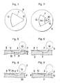
- Figure 1 is a plan view of a piston head showing the first embodiment of the present invention;
- Figure 2 is a vertical sectional right side view showing the principal parts of a main combustion chamber and a swirl chamber for a vertical diesel engine according to the present invention;
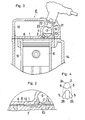
- Figure 3 is a vertical sectional right side view showing the principal part including a cylinder block and a cylinder head for the vertical diesel engine;
- Figure 4 is an explanatory view of an injection passage formed in a mouthpiece in Fig.3;
- Figure 5 is a vertical sectional right side view of a piston head showing the second embodiment of the present invention;
- Figure 6 is a view showing the third embodiment in correspondence with Fig.5;
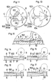
- Figure 7 is a view showing the fourth embodiment in correspondence with Fig.1;
- Figure 8 is a view showing the fourth embodiment in correspondence with Fig.5;
- Figure 9 is a view showing the fifth embodiment in correspondence with Fig.5;
- Figure 10 is a view showing the sixth embodiment in correspondence with Fig.5;
- Figure 11 is a view showing the seventh embodiment including a piston head provided with vale recesses, in correspondence with Fig.1;
- Figure 12 is a view showing the seventh embodiment in correspondence with Fig.2;
- Figure 13 is a view showing a relative positional relation among a cocavity, valve recesses and other portions in correspondence with Fig.11;
- Figures 14 through 17 are views showing respectively other embodiments of the concavity in the case of the piston head provided with valve recesses;
- Figure 14 is a vertical sectional view of the piston head in accordance with the second embodiment;
- Figure 15 is a view in accordance with the third embodiment and in correspondence with Fig.13;
- Figure 16 is a view in accordance with the fourth embodiment and in correspondence with Fig.13;
- Figure 17 is a view in accordance with the fifth embodiment and in correspondence with Fig.13;
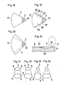
- Figures 18 through 20 are views showing respectively embodiments of relative relations between the spreading directions of combustion gas injected from the injection passage and the concavity;
- Figure 18 is a plan view of the concavity showing the state wherein both directions are in accord each other;
- Figure 19 is a plan view of the concavity showing the state wherein both directions are shifted longitudinally to each other;
- Figure 20 is a plan view of the concavity showing the state wherein the spreading angle of the concavity is larger than that of the combustion gas stream;
- Figures 21 through 24 are views showing other embodiments of injection passage;
- Figure 21 is a view of the injection passage comprising a main passage of an elliptic cylinder and side channels connected therewith, in correspondence with Fig.4;
- Figure 22 ia a view showing the injection passage having a small elongate hole at the upper end and a large elongate hole at the lower end, whose longitudinal directions are coincied each other, in correspondence with Fig.4;
- Figure 23 is a view showing the injection passage having an elongate hole at the upper end and a circular hole at the lower end, in correspondence with Fig.4; and
- Figure 24 is a view of the passage having a small elongate hole at the upper end and a large elongate hole at the lower end, whose longitudinal directions are crossed each other, in correspondence with Fig.4.
- As shown in Fig.s 1 through 4, in the preferred embodiment of the present invention, a diesel engine E has a
cylider block 14 provided with acylinder 15 around the center thereof, which guides apiston 6 slidably reciprocatingly therein. On the upside of thecylider block 14, there is mounted acylinder head 16, which has a cavity caved in the backward wall facing to amain combustion chamber 1 and amouthpiece 20 fitted in the aperture formed in the lower portion of thecavity 19. Aswirl chamber 3 is formed by the upper hemispherical portion of thecavity 19 and the lower hemispherical portion caved in themouthpiece 20. - The
cylider head 16 has afuel injection nozzle 22 mounted in abore 21 which is bored through from the upper end of the backward wall to thecavity 19 therein with theinjection tip 23 being projected in theswirl chamber 3. - In the
mouthpiece 20, there is provided aninjection passage 2 inclined backward, that is directed obliquely in such a way that theaxis 4 of theinjection passage 2 gets near the center of themain combustion chamber 1 as progressing to themain combustion chamber 1 from theswirl chamber 3. - As shown in Fig.4, the
injection passage 2 comprises a central round throughhole 24 as for a main injection channel andside channels 25 in the shape of swelled ridge connected thereto at somewhat forward positions from the transverse axis of thehole 24. Theside channels 25 are formed in such configuration that the opposite side walls thereof spread right and left symmetrically relative to the axis of the round throughhole 24 as progressing to themain combustion chamber 1 from theswirl chamber 3 and so that the combustion gas is guided to spread to both side thereof when it is injected from theswirl chamber 3 to themain combustion chamber 1. - With referrence to Fig.s 1 and 2, on the top surface of the
piston head 8, there is provided aconcavity 7 in a shape of a fan unfolded to an angle of ab.60 degree so as to face to the outlet of theinjection passage 2 at theinlet end 10 corresponding with the pivot portion of the fan. Theconcavity 7 is formed deepest at theinlet end 10 thereof and so as to get shallower as progressing to theforward end 12 as for the outlet end. Further, since thecavity 7 is positioned around at the central portion of the piston top surface so as for theinlet end 10 to face to the outlet of theinjection passage 2 in themain combustion chamber 1, the stream of combustion gas injected from thepassage 2 is guided to spread smoothly and properly throughout theconcavity 7 from theinlet end 10 to theoutlet end 12 thereof. - The longitudinal sectional configuration of the
concavity 7 comprises a spherical portion formed at theinlet end 10 and a single-curved surface( having not a curvature longitudinally but having that transversely ) formed like a ramp ascending from theinlet end 10 to theoutlet end 12 and smoothly connected thereto. - The function of the above-mentioned embodiment is now to be described hereinafter.
- Since the
injection passage 2 is directed towards theinlet end 10 of theconcavity 7 formed on thepiston head 8 even while thepiston 6 passing by the top dead center thereof, the stream of combustion gas injected into themain combustion chamber 1 through thepassage 2 pushes away the air in theconcavity 7 towards theoutlet end 12 smoothly without any resistances and also it is prevented that the stream of combustion gas is spreaded excessively by the approach of the piston top surface to the outlet of thepassage 2. Thereupon, the stream of combustion gas can be diffused properly without causing turbulences in themain combustion chamber 1 in order to mix with the air effectively throughout themain combustion chamber 1. - Accordingly, the present invention can obtain the following advantages.
- (1) Since the stream of combustion gas injected from the
swirl chamber 3 is diffused properly without causing turbulences in themain combustion chamber 1 so as to facilitate the mixing with the air effectively throughout thechamber 1, a specific air utilization can be enhanced. - (2) Since a local shortage of the air in the
main combustion chamber 1 can be solved by the improvement of the diffusion of the combustion gas stream, carbon is scarcely produced therein. Thus, the sticking of the piston-rings can be prevented effectively between the sliding surfaces of thecylinder 15 and thepiston 6. - (3) Since the stream of combustion gas is smoothly injected forwardly in the
main combustion chamber 1 even while the piston passing by the top dead center thereof, the local overheating for the piston head 18 by the combustion gas maldistributed near the outlet of thepassage 2 can be prevented so as for the thermal strains in thepiston 6 to be removed. - In addition, modified embodiments are now to be described hereinafter.
- That is, since it is required as a necessary condition that the
concavity 7 is to be formed in such a configuration as spreading right and left as progressing from theinlet end 10 to theoutlet end 12, the longitudinal sectional configuration thereof is not limitted exclusively to the above-mentioned embodiment but may be modified as follows. - In the second embodiment of the
concavity 7 provided in thepiston head 8 as shown in Fig.5, theconcavity 7 comprises an obliqueflat surface 30 inclinded backwards at theinlet end 10 , a holizontalflat surface 31 formed in a same depth from theinlet end 10 to the midway portion thereof and a single-curved concave 32( having a curvature longitudinally ) ascending from the midway portion to theoutlet end 12 and connected smoothly to theflat surface 31. - In this embodiment, since the
concavity 7 has a larger capacity due to the formation of the concave 32 in comparison with that of the first embodiment, an excessive spreading of the stream of combustion gas can be prevented effectively. - In the third embodiment of the
concavity 7 shown in Fig.6, the edge between the theflat surface 30 and the piston top surface at theinlet end 10 as shown in the first embodiment is smoothly rounded so as to continuosly smoothly connect thecavity 7 to the top surface of thepiston head 8. Therefore, the generation of cracks and/or a heat point can be prevented owing to the removal of the sharp edge at theinlet end 10. - In the fourth embodiment of the
concavity 7 shown in Figs 7 and 8, the area from the midway portin to the outlet end 12 of theconcavity 7 in the third embodiment is formed in an oblique single-curved concave 34 having a curvature transversely and ascending forwardly, and the centralflat surface 31 and the concave 34 are connected to each other like a folded line. - In the fifth embodiment of the
concavity 7 shown in Fig.9, theinlet end 10 shown in the first embodiment is modified so as to be formed by a vertical flat surface. - In the sixth embodiment of the
concavity 7 shown in Fig.10, themidway portion 40 between theinlet end 10 and theoutlet end 12 is formed deepest. Thereupon, theconcavity 7 is formed so as to progressively descend from theinlet end 10 to themidway portion 40 and ascend from themidway portion 40 to theoutlet end 12. The flow resistance for the stream of combustion gas injected from theinjection passage 2 can be reduced effectively because the depth of theconcavity 7 gets gradually increased as progressing from theinlet end 10 to themidway portion 40. - In the seventh embodiment shown in Fig.s 11 and 12, the
piston head 8 is provided withvalve recesses 100 in order to avoid the interferences between thepiston head 8 and an intake and an exhaust valves. Theintake valve recess 100a of large aperture and theexhaust valve recess 100b of small aperture are respectively formed in a proper depth at the left side and at the right side of a center line C on thepiston head 8. - In this case, the
intake valve recess 100a is overlapped partially with the right half around the outlet end 12 ( overlapped part being indicated by 101 ), and theexhaust valve recess 100b is overlapped partially with the left half around the outlet end 12 ( overlapped part being indicated by 102 ). - The longitudinal sectional configuration of the
concavity 7 comprises aspherical inlet end 10 and an oblique flat surface ascending from theinlet end 10 to theoutlet end 12 and connected smoothly thereto. - Generally, as the compression ratio and the volume ratio of the swirl chamber being constant, the volume of the
main combustion chamber 1 is also defined to be constant. And the volume of themain combustion chamber 1 consists of respective volumes of a disk-like clearance between the underside of thecylinder head 16 and the top surface of thepiston head 8, the valve recesses 100 and theconcavity 7. Further, as the volume of the cylidrical clearance and the volume of the valve recesss are respectively defined to be constant by the clearance at the top dead center of thepiston 6 for the former and by the strokes of the intake and exhaust valves for the latter, the residual volume of theconcavity 7 is to be defined constant uncoditionally. - In this embodiment, since the volume of the
concavity 7 is reduced by the overlapped portions thereof, theconcavity 7 is to be deepened as compensation for the overlapped portions in order to maintain the constant volume of theconcavity 7. Thereupon, the resistance for the combustion gas stream is reduced remarkably in theconcavity 7. Accordingly, the excessive spreading of the combustion gas stream can be prevented more effectively than in the foregoing embodiments owing to the space enlarged at the outlet of theinjection passage 2. - On the other hands, in the Fig.7 showing another embodiment about a relative arrangement between the
concavity 7 and the valve recesses 100, with differing from the seventh embodiment, theinlet end 10 of theconcavity 7 is located on the center line C of thepiston head 8, and theintake valve recess 100a and theexhaust valve recess 100b are respectively provided with theedge portions piston head 8. Hence, this embodiment solves the problem that theedge portions - Fig.s 14 through 17 show the other embodiments having the valve recesses. Fig.14 corresponds to the second embodiment, Fig.15 does to the third one, Fig.16 does to the fourth one, and Fig.17 does to the fifth one respectively.
- On the other hands, the relative positional relation between the
injection passage 2 and theconcavity 7 is not only limited to one embodiment but may be varied to many types of embodiments. - Fig.18 shows other embodiment of the
concavity 7, wherein theinlet end 10 thereof is aligned with the outlet of theinjection passage 2 and the spread angle thereof is in accord with that of the stream of combustion gas injected from the passage. - In Fig.19 showing other embodiment having the
concavity 7 whose spread angle is settled under the same condition as in Fig.18, the outlet of theinjection passage 2 is positioned a little forwards with respect to theinlet end 10 of theconcavity 7. Since the stream of combustion gas injected from thepassage 2 is to flow through with its oposite side edges 35 being spaced a little inwards from the oposite side edges 36 of theconcavity 7, vacuum pressure is to be produced adjacently along the outside of the side edges 35. Accordingly,air 37 is to be sucked into theconcavity 7 through the side edges 36 so as to facilitate more effectively the mixing with the stream of combustion gas in themain combustion chamber 1. - Fig.20 shows such an unfolded-fan shaped
concavity 7 as having a spread angle settled a little larger than that of the combustion gas stream. As for the configuration of theconcavity 7 which gradually spreads forwardly on both sides thereof, not only the shape of an folded-fan but also, for example the shape of a triangle, a crescent or leaf of ginkgo, etc. can be applied thereto. - Further, the
injection passage 2 may have only such a basic configuration as it guides the stream of combustion gas so as to gradually spread right and left, that is, such an injection passage is enough as to gradually spread the stream of combustion gas right and left as progressing to the main conbustion chamber. - Accordingly, besides the first embodiment, the following variations can be applied to the
injection passage 2, for example which comprising a main passage of an elliptical cylinder and side channels connected to said main passage at the laterals thereof as shown in Fig.21, having elongate holes of which longitudinal directions coincid to each other respectively at the upper and the lower ends as shown in Fig.22, having respectively an elongate hole at the upper end and a circular hole at the lower end as shown in Fig.23, and having a transversely elongate hole and a longitudinal elongate hole of which longitudinal directions are crossed each other, respectively at the upper and the lower ends as shown in Fig.24. - Although the invention has been disclosed in relation to preferred embodiments thereof, it will become apparent to those skilled in the art that numerous modifications and variations can be made within the scope and spirit of the invention as defined by the attached claims.
Claims (16)
Applications Claiming Priority (2)
| Application Number | Priority Date | Filing Date | Title |
|---|---|---|---|
| JP119682/86 | 1986-05-23 | ||
| JP61119682A JPH0643806B2 (en) | 1986-05-23 | 1986-05-23 | Whirlpool combustion chamber of diesel engine |
Publications (3)
| Publication Number | Publication Date |
|---|---|
| EP0247732A2 true EP0247732A2 (en) | 1987-12-02 |
| EP0247732A3 EP0247732A3 (en) | 1989-01-18 |
| EP0247732B1 EP0247732B1 (en) | 1991-03-27 |
Family
ID=14767437
Family Applications (1)
| Application Number | Title | Priority Date | Filing Date |
|---|---|---|---|
| EP87303759A Expired - Lifetime EP0247732B1 (en) | 1986-05-23 | 1987-04-28 | Swirl chamber type combustion chamber for diesel engine |
Country Status (6)
| Country | Link |
|---|---|
| US (1) | US4798183A (en) |
| EP (1) | EP0247732B1 (en) |
| JP (1) | JPH0643806B2 (en) |
| CA (1) | CA1329900C (en) |
| DE (1) | DE3768855D1 (en) |
| ES (1) | ES2021358B3 (en) |
Cited By (3)
| Publication number | Priority date | Publication date | Assignee | Title |
|---|---|---|---|---|
| EP0407974A1 (en) * | 1989-07-10 | 1991-01-16 | Nissan Motor Co., Ltd. | Flame dispersion arrangement for swirl chamber type diesel engine piston crown |
| EP0828065A3 (en) * | 1996-09-06 | 1998-08-19 | Kubota Corporation | Divided combustion chamber for diesel engine |
| EP3872332A4 (en) * | 2018-10-26 | 2022-08-03 | Kubota Corporation | ELECTRONIC FUEL INJECTION TYPE DIESEL ENGINE |
Families Citing this family (12)
| Publication number | Priority date | Publication date | Assignee | Title |
|---|---|---|---|---|
| JP2504505B2 (en) * | 1988-02-03 | 1996-06-05 | 日産自動車株式会社 | Vortex chamber type diesel engine combustion chamber |
| US5305720A (en) * | 1992-02-28 | 1994-04-26 | Mitsubishi Jidosha Kogyo Kabushiki Kaisha | Internal combustion engine |
| US5417189A (en) * | 1993-03-08 | 1995-05-23 | Chrysler Corporation | High speed indirect injection diesel engine |
| ES2092769T3 (en) * | 1993-07-06 | 1996-12-01 | Kubota Kk | DIVIDED CHAMBER DIESEL ENGINE. |
| EP1402158B1 (en) * | 2001-06-06 | 2005-12-14 | Textron Lycoming | Improved cylinder assembly for an aircraft engine |
| DE60332203D1 (en) * | 2002-09-27 | 2010-06-02 | Kubota Kk | Combustion chamber with swirl chamber for a diesel engine |
| CA2500642A1 (en) * | 2002-10-02 | 2004-04-15 | Reveal Imaging Technologies, Inc. | Folded array ct baggage scanner |
| US7224765B2 (en) * | 2002-10-02 | 2007-05-29 | Reveal Imaging Technologies, Inc. | Computed tomography system |
| US7284524B2 (en) | 2005-02-25 | 2007-10-23 | Lycoming Engines, A Division Of Avco Corporation | Cylinder head assemblies |
| CN105849380B (en) | 2013-09-25 | 2019-08-02 | 艾尼森生态技术有限公司 | self-cooling engine |
| US9843062B2 (en) | 2016-03-23 | 2017-12-12 | Energyield Llc | Vortex tube reformer for hydrogen production, separation, and integrated use |
| US9840413B2 (en) | 2015-05-18 | 2017-12-12 | Energyield Llc | Integrated reformer and syngas separator |
Family Cites Families (31)
| Publication number | Priority date | Publication date | Assignee | Title |
|---|---|---|---|---|
| DE133793C (en) * | ||||
| US1917883A (en) * | 1932-01-25 | 1933-07-11 | Campbell Wyant & Cannon Co | Combustion chamber |
| DE854716C (en) * | 1938-07-20 | 1952-11-06 | Daimler Benz Ag | Self-igniting, air-compressing internal combustion engine with an antechamber which is arranged in the cylinder head and forms only a smaller part of the combustion chamber |
| US2803229A (en) * | 1954-03-22 | 1957-08-20 | Daimler Benz Ag | Fuel injection engine |
| US2816534A (en) * | 1956-05-24 | 1957-12-17 | Louis O French | Fuel injection apparatus |
| DE1211435B (en) * | 1957-07-06 | 1966-02-24 | Maschf Augsburg Nuernberg Ag | Air-compressing, self-igniting internal combustion engine |
| GB930498A (en) * | 1959-10-06 | 1963-07-03 | Rover Co Ltd | Internal combustion engines of the liquid fuel injection compression ignition type |
| US3063434A (en) * | 1959-11-27 | 1962-11-13 | Herbert H Haas | Internal combustion engine |
| FR1350803A (en) * | 1962-12-18 | 1964-01-31 | Hotchkiss Brandt | Internal combustion engine |
| FR1436612A (en) * | 1965-02-08 | 1966-04-29 | Applic Tech | Improvements to internal combustion engines of the thermally insulated chamber type |
| JPS5218645Y2 (en) * | 1974-05-02 | 1977-04-27 | ||
| JPS555707Y2 (en) * | 1974-08-06 | 1980-02-08 | ||
| JPS5139308A (en) * | 1974-09-28 | 1976-04-01 | Kubota Ltd | Deiizerukikanno nenshoshitsu |
| JPS5229512A (en) * | 1975-09-02 | 1977-03-05 | Nissan Diesel Motor Co Ltd | Eddy current chamber type diesel engine |
| JPS5229513A (en) * | 1975-09-02 | 1977-03-05 | Nissan Diesel Motor Co Ltd | Diesel engine |
| JPS5949405B2 (en) * | 1976-04-26 | 1984-12-03 | 株式会社クボタ | Secondary combustion chamber engine |
| JPS6024289B2 (en) * | 1976-06-09 | 1985-06-12 | いすゞ自動車株式会社 | combustion chamber |
| JPS5325709A (en) * | 1976-08-23 | 1978-03-09 | Kubota Ltd | Combustion chamber for auxiliary combustion type engine |
| JPS5575528A (en) * | 1978-12-04 | 1980-06-06 | Honda Motor Co Ltd | Internal combustion engine with subsidiary combustion chamber |
| DE2923869A1 (en) * | 1979-06-13 | 1980-12-18 | Daimler Benz Ag | AIR COMPRESSING INTERNAL COMBUSTION ENGINE WITH CHAMBER |
| JPS572650U (en) * | 1980-06-05 | 1982-01-08 | ||
| JPS6011524B2 (en) * | 1980-09-24 | 1985-03-26 | 住友電気工業株式会社 | How to extend and tie up overhead ground wires |
| JPS5851215A (en) * | 1981-09-22 | 1983-03-25 | Mitsubishi Heavy Ind Ltd | Combustion chamber for vortex chamber type diesel engine |
| JPS58126421A (en) * | 1982-01-25 | 1983-07-27 | Mitsubishi Heavy Ind Ltd | Main combustion chamber of subchamber type engine |
| JPS58180719A (en) * | 1982-04-17 | 1983-10-22 | Honda Motor Co Ltd | Torch ignition type gasoline internal-combustion engine |
| JPS5918225A (en) * | 1982-07-21 | 1984-01-30 | Isuzu Motors Ltd | Structure of piston head of direct ignition type diesel engine |
| JPS5991420U (en) * | 1982-12-14 | 1984-06-21 | 日産自動車株式会社 | Swirl chamber diesel engine |
| JPS59158315A (en) * | 1983-02-28 | 1984-09-07 | Hino Motors Ltd | Diesel engine combustion chamber |
| JPS60153420A (en) * | 1984-01-21 | 1985-08-12 | Mitsubishi Heavy Ind Ltd | Combustion chamber of double cell type engine |
| DE3519835A1 (en) * | 1984-06-07 | 1985-12-12 | Nissan Motor Co., Ltd., Yokohama, Kanagawa | COMBUSTION ENGINE |
| DE3520775A1 (en) * | 1984-06-12 | 1985-12-12 | Nissan Motor Co., Ltd., Yokohama, Kanagawa | Diesel engine with a swirl chamber and a flame distribution recess molded into the piston crown |
-
1986
- 1986-05-23 JP JP61119682A patent/JPH0643806B2/en not_active Expired - Lifetime
-
1987
- 1987-04-28 DE DE8787303759T patent/DE3768855D1/en not_active Expired - Lifetime
- 1987-04-28 ES ES87303759T patent/ES2021358B3/en not_active Expired - Lifetime
- 1987-04-28 EP EP87303759A patent/EP0247732B1/en not_active Expired - Lifetime
- 1987-04-30 CA CA000535999A patent/CA1329900C/en not_active Expired - Lifetime
- 1987-05-21 US US07/053,338 patent/US4798183A/en not_active Expired - Lifetime
Cited By (3)
| Publication number | Priority date | Publication date | Assignee | Title |
|---|---|---|---|---|
| EP0407974A1 (en) * | 1989-07-10 | 1991-01-16 | Nissan Motor Co., Ltd. | Flame dispersion arrangement for swirl chamber type diesel engine piston crown |
| EP0828065A3 (en) * | 1996-09-06 | 1998-08-19 | Kubota Corporation | Divided combustion chamber for diesel engine |
| EP3872332A4 (en) * | 2018-10-26 | 2022-08-03 | Kubota Corporation | ELECTRONIC FUEL INJECTION TYPE DIESEL ENGINE |
Also Published As
| Publication number | Publication date |
|---|---|
| US4798183A (en) | 1989-01-17 |
| EP0247732B1 (en) | 1991-03-27 |
| DE3768855D1 (en) | 1991-05-02 |
| CA1329900C (en) | 1994-05-31 |
| EP0247732A3 (en) | 1989-01-18 |
| ES2021358B3 (en) | 1991-11-01 |
| JPH0643806B2 (en) | 1994-06-08 |
| JPS62276211A (en) | 1987-12-01 |
Similar Documents
| Publication | Publication Date | Title |
|---|---|---|
| US4798183A (en) | Swirl chamber type combustion chamber for diesel engine | |
| US4122804A (en) | Diesel engine combustion chambers | |
| KR910002897B1 (en) | Swirl chamber type combustion chamber of diesel engine | |
| JPH11190217A (en) | Direct injection diesel engine | |
| JP3404288B2 (en) | 2 cycle engine | |
| JPH06212974A (en) | Two-stroke cycle engine | |
| GB1561729A (en) | Pre-combustion chamber diesel engines | |
| JPH04140418A (en) | Piston structure of diesel engine having subchamber | |
| JPH084535A (en) | Direct injection diesel engine pistons | |
| JP3554385B2 (en) | Main combustion chamber of sub-chamber diesel engine | |
| JP3116612B2 (en) | In-cylinder direct injection diesel engine | |
| JP3820688B2 (en) | In-cylinder direct injection spark ignition engine | |
| JPS63179122A (en) | Diesel engine whirlpool combustion chamber | |
| JPH01257714A (en) | Diesel engine swirl combustion chamber | |
| JPH05113120A (en) | 2 cycle internal combustion engine with sub chamber | |
| JPH0619802Y2 (en) | Subchamber diesel engine combustion chamber | |
| JPH0658149A (en) | Shape of main combustion chamber of vortex chamber type diesel engine | |
| JPH10339137A (en) | Combustion chamber structure of vortex chamber type diesel engine | |
| JP2506676Y2 (en) | 2-cycle diesel engine | |
| JPH0730329U (en) | Combustion chamber of a sub-chamber internal combustion engine | |
| JPH05156943A (en) | Combustion chamber of swirl chamber type diesel engine | |
| JPS6118185Y2 (en) | ||
| JPH0521149U (en) | Combustion chamber of sub-chamber internal combustion engine | |
| JPH08260979A (en) | Diesel engine auxiliary chamber combustion chamber | |
| JP2002174123A (en) | Diesel engine combustion chamber |
Legal Events
| Date | Code | Title | Description |
|---|---|---|---|
| PUAI | Public reference made under article 153(3) epc to a published international application that has entered the european phase |
Free format text: ORIGINAL CODE: 0009012 |
|
| AK | Designated contracting states |
Kind code of ref document: A2 Designated state(s): DE ES FR GB |
|
| PUAL | Search report despatched |
Free format text: ORIGINAL CODE: 0009013 |
|
| AK | Designated contracting states |
Kind code of ref document: A3 Designated state(s): DE ES FR GB |
|
| 17P | Request for examination filed |
Effective date: 19890213 |
|
| 17Q | First examination report despatched |
Effective date: 19890619 |
|
| GRAA | (expected) grant |
Free format text: ORIGINAL CODE: 0009210 |
|
| AK | Designated contracting states |
Kind code of ref document: B1 Designated state(s): DE ES FR GB |
|
| REF | Corresponds to: |
Ref document number: 3768855 Country of ref document: DE Date of ref document: 19910502 |
|
| ET | Fr: translation filed | ||
| K2C3 | Correction of patent specification (complete document) published |
Effective date: 19910327 |
|
| PLBE | No opposition filed within time limit |
Free format text: ORIGINAL CODE: 0009261 |
|
| STAA | Information on the status of an ep patent application or granted ep patent |
Free format text: STATUS: NO OPPOSITION FILED WITHIN TIME LIMIT |
|
| 26N | No opposition filed | ||
| REG | Reference to a national code |
Ref country code: FR Ref legal event code: ST |
|
| REG | Reference to a national code |
Ref country code: FR Ref legal event code: RN |
|
| REG | Reference to a national code |
Ref country code: FR Ref legal event code: ER |
|
| REG | Reference to a national code |
Ref country code: FR Ref legal event code: FC |
|
| REG | Reference to a national code |
Ref country code: GB Ref legal event code: IF02 |
|
| PGFP | Annual fee paid to national office [announced via postgrant information from national office to epo] |
Ref country code: FR Payment date: 20060410 Year of fee payment: 20 |
|
| PGFP | Annual fee paid to national office [announced via postgrant information from national office to epo] |
Ref country code: DE Payment date: 20060420 Year of fee payment: 20 |
|
| PGFP | Annual fee paid to national office [announced via postgrant information from national office to epo] |
Ref country code: GB Payment date: 20060426 Year of fee payment: 20 |
|
| PGFP | Annual fee paid to national office [announced via postgrant information from national office to epo] |
Ref country code: ES Payment date: 20060427 Year of fee payment: 20 |
|
| PG25 | Lapsed in a contracting state [announced via postgrant information from national office to epo] |
Ref country code: ES Free format text: LAPSE BECAUSE OF EXPIRATION OF PROTECTION Effective date: 20070430 |
|
| REG | Reference to a national code |
Ref country code: GB Ref legal event code: PE20 |
|
| REG | Reference to a national code |
Ref country code: ES Ref legal event code: FD2A Effective date: 20070430 |
|
| PG25 | Lapsed in a contracting state [announced via postgrant information from national office to epo] |
Ref country code: GB Free format text: LAPSE BECAUSE OF EXPIRATION OF PROTECTION Effective date: 20070427 |