EP0247807A1 - Entspannungsventil mit Überdrucküberwachung für Flüssigkeitsbehälter - Google Patents
Entspannungsventil mit Überdrucküberwachung für Flüssigkeitsbehälter Download PDFInfo
- Publication number
- EP0247807A1 EP0247807A1 EP19870304573 EP87304573A EP0247807A1 EP 0247807 A1 EP0247807 A1 EP 0247807A1 EP 19870304573 EP19870304573 EP 19870304573 EP 87304573 A EP87304573 A EP 87304573A EP 0247807 A1 EP0247807 A1 EP 0247807A1
- Authority
- EP
- European Patent Office
- Prior art keywords
- valve
- tank
- piston
- snubber
- pressure
- Prior art date
- Legal status (The legal status is an assumption and is not a legal conclusion. Google has not performed a legal analysis and makes no representation as to the accuracy of the status listed.)
- Granted
Links
Images

Classifications
-
- F—MECHANICAL ENGINEERING; LIGHTING; HEATING; WEAPONS; BLASTING
- F16—ENGINEERING ELEMENTS AND UNITS; GENERAL MEASURES FOR PRODUCING AND MAINTAINING EFFECTIVE FUNCTIONING OF MACHINES OR INSTALLATIONS; THERMAL INSULATION IN GENERAL
- F16K—VALVES; TAPS; COCKS; ACTUATING-FLOATS; DEVICES FOR VENTING OR AERATING
- F16K17/00—Safety valves; Equalising valves, e.g. pressure relief valves
- F16K17/02—Safety valves; Equalising valves, e.g. pressure relief valves opening on surplus pressure on one side; closing on insufficient pressure on one side
- F16K17/04—Safety valves; Equalising valves, e.g. pressure relief valves opening on surplus pressure on one side; closing on insufficient pressure on one side spring-loaded
- F16K17/048—Safety valves; Equalising valves, e.g. pressure relief valves opening on surplus pressure on one side; closing on insufficient pressure on one side spring-loaded combined with other safety valves, or with pressure control devices
-
- B—PERFORMING OPERATIONS; TRANSPORTING
- B65—CONVEYING; PACKING; STORING; HANDLING THIN OR FILAMENTARY MATERIAL
- B65D—CONTAINERS FOR STORAGE OR TRANSPORT OF ARTICLES OR MATERIALS, e.g. BAGS, BARRELS, BOTTLES, BOXES, CANS, CARTONS, CRATES, DRUMS, JARS, TANKS, HOPPERS, FORWARDING CONTAINERS; ACCESSORIES, CLOSURES, OR FITTINGS THEREFOR; PACKAGING ELEMENTS; PACKAGES
- B65D90/00—Component parts, details or accessories for large containers
- B65D90/22—Safety features
- B65D90/32—Arrangements for preventing, or minimising the effect of, excessive or insufficient pressure
- B65D90/34—Venting means
-
- F—MECHANICAL ENGINEERING; LIGHTING; HEATING; WEAPONS; BLASTING
- F16—ENGINEERING ELEMENTS AND UNITS; GENERAL MEASURES FOR PRODUCING AND MAINTAINING EFFECTIVE FUNCTIONING OF MACHINES OR INSTALLATIONS; THERMAL INSULATION IN GENERAL
- F16K—VALVES; TAPS; COCKS; ACTUATING-FLOATS; DEVICES FOR VENTING OR AERATING
- F16K17/00—Safety valves; Equalising valves, e.g. pressure relief valves
- F16K17/36—Safety valves; Equalising valves, e.g. pressure relief valves actuated in consequence of extraneous circumstances, e.g. shock, change of position
-
- Y—GENERAL TAGGING OF NEW TECHNOLOGICAL DEVELOPMENTS; GENERAL TAGGING OF CROSS-SECTIONAL TECHNOLOGIES SPANNING OVER SEVERAL SECTIONS OF THE IPC; TECHNICAL SUBJECTS COVERED BY FORMER USPC CROSS-REFERENCE ART COLLECTIONS [XRACs] AND DIGESTS
- Y10—TECHNICAL SUBJECTS COVERED BY FORMER USPC
- Y10T—TECHNICAL SUBJECTS COVERED BY FORMER US CLASSIFICATION
- Y10T137/00—Fluid handling
- Y10T137/7722—Line condition change responsive valves
- Y10T137/7781—With separate connected fluid reactor surface
- Y10T137/7784—Responsive to change in rate of fluid flow
- Y10T137/7785—Valve closes in response to excessive flow
-
- Y—GENERAL TAGGING OF NEW TECHNOLOGICAL DEVELOPMENTS; GENERAL TAGGING OF CROSS-SECTIONAL TECHNOLOGIES SPANNING OVER SEVERAL SECTIONS OF THE IPC; TECHNICAL SUBJECTS COVERED BY FORMER USPC CROSS-REFERENCE ART COLLECTIONS [XRACs] AND DIGESTS
- Y10—TECHNICAL SUBJECTS COVERED BY FORMER USPC
- Y10T—TECHNICAL SUBJECTS COVERED BY FORMER US CLASSIFICATION
- Y10T137/00—Fluid handling
- Y10T137/7722—Line condition change responsive valves
- Y10T137/7781—With separate connected fluid reactor surface
- Y10T137/7835—Valve seating in direction of flow
Definitions
- This invention relates generally to pressure relief valves for fluid storage tanks and, more particularly, to such a valve which includes a snubber assembly to prevent the valve from opening for a short period of time when the valve is subjected to a sudden or rapid pressure rise, such as occurs in a surge of the fluid retained in such tanks.
- Tanks for retaining fluid, particularly flammable or corrosive liquids commonly are provided with a pressure relief valve so as to limit the internal pressure in the tank to a predetermined value for safety.
- a pressure relief valve so as to limit the internal pressure in the tank to a predetermined value for safety.
- pressure relief valves Under normal conditions when the pressure inside the tank rises slowly as in normal storage of flammable liquids, such valves are opened at a predetermined pressure so as to relieve the excess pressure in the tank by venting to atmosphere. Thereafter, when the pressure inside of the tank is reduced to a safe level, the valve is closed to maintain the tank under desired pressure.
- Patents 1,893,942 3,845,876 1,942,630 3,854,623 2,016,278 3,913,601 2,847,149 3,938,692 3,186,682 3,945,395 3,580,275 3,974,850 3,365,096 4,287,910 3,744,670 4,593,711 3,757,987
- Such a pressure relief valve for flammable or corrosive liquid tanks, it is desirable to include structure to temporarily prevent or control spillage or release of gases from within the tank in the event of a sudden pressure rise or surge of such liquid.
- Such surge control structure ideally is operable to maintain the pressure relief valve in closed condition for a short period of time to prevent spillage of the tank contents which normally would occur in prior art valves which do not include such surge control feature. Spillage or release of liquid might occur if a tank is upset or rolled over, such as in an accident, creating a sudden pressure rise resulting from liquid surge.
- a first object of the invention is to provide a valve mounted on a tank shell and characterized by a housing with an internal portion disposed within the tank and an external portion disposed outside the tank, the internal portion having a closed expansion chamber, and a pilot piston operable in the expansion chamber in the valve between a closed position and an open position in which the tank is vented to atmosphere.
- the piston includes a snubber valve chamber opening between the closed expansion chamber and the tank.
- a separate snubber valve assembly is movably retained within the chamber, is capable of movement independent of the piston, and is provided with a plurality of openings to permit passage of the tank contents therethrough into the closed expansion chamber to move the piston from the first to the second position after a predetermined time delay after a rapid pressure increase within the tank.
- Gases retained within the tank which build slowly move into the valve through the passageways in the snubber assembly and fill the expansion chamber to move the piston slowly to its open position. When pressure in the tank is relieved, the gases in the expansion chamber are released back into the tank to permit the piston to return to its initial position by operation of a valve spring so as to close the valve.
- the valve functions as a surge control in the event of sudden pressure rise or surge of liquid in the tank. Liquid surging against the valve causes the snubber assembly to move to a partially closed position in which the passageways are blocked and the only path available for movement of liquid into the valve is through the reduced dimension orifice. Surging liquid thereby moves into the expansion chamber at a slowed rate, providing for extended time for the chamber to fill and move the piston to its open position.
- the time for movement of the valve is adjustable by variation of the size of the orifice, the volume of the expansion chamber, and the force of springs which are operable against the valve and the snubber assembly.
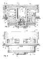
- valve 10 of the invention is shown mounted or installed on the shell 12 of a tank by bolts 14 which pass through apertures in the shell and into threaded openings in the body 16 of the valve.
- a gasket 18 is positioned between the valve body and the tank shell to seal the installation.
- an upper or external portion 20 of valve 10 is disposed outside of the tank and above shell 12 in atmosphere and a lower or internal portion 22 of the valve is disposed within the tank and below shell 12.
- External portion 20 of valve 10 includes vent openings 24 which, when the valve is moved to its opened position described below, permit gases and liquid from within the tank to move to atmosphere.
- Valve body 16 includes a centrally located hub 26 with radial supports 28 extending to peripheral wall 30.
- Upper external portion 20 is closed by cap 32 having a peripheral groove 34 for retaining an O-ring 36 to seal the cap within the upper external portion.
- Cap 32 is retained within portion 20 by retaining ring 38 which seats in groove 40 provided in portion 20.
- a piston 42 with poppet 44 is positioned within the valve body 16.
- Piston 42 is formed with a peripheral groove 45 for retaining an O-ring 46 to seal the piston against the inner-facing surface 48 of upper portion 20.
- Poppet 44 is positioned upon the lower end 49 of piston 42 adjacent gasket 50 which is maintained in contact with poppet 44 by gasket retainer 52.
- Poppet 44 is rigidly secured to piston 42 against gasket 50 and retainer 52 by retaining nut 54 threadedly engaged upon the lower end 49 of piston 42.
- Lower end 49 of piston 42 is formed with a chamber 56 within which snubber surge valve assembly 58 is movably positioned.
- Snubber assembly 58 is retained within chamber 56 by retaining ring 60 which seats in groove 62 formed in the wall of chamber 56.
- Spring 63 is operable against flange 64 of snubber assembIy 58 and shoulder 66 which defines a reduced dimension channel 68 that opens from chamber 56 into piston expansion chamber 70 in the upper portion 20 of valve body 16.
- Main valve spring 72 is restrained in compression and operable against piston 42 and hub 26 to urge piston 42 into its normally closed position shown in Fig. 1 adjacent cap 32.
- Snubber surge valve assembly 58 is formed with two chambers 74, 76 disposed cojacent each other with wall 78 therebetween. Open end 79 of chamber 74 is defined by flange 64 and faces the internal confines of tank shell 12. Passageways 80 are formed in the walls 82, 84 of chambers 74, 76, said passageways opening into chamber 56 in which snubber assembly 58 is retained. Open end 86 of chamber 76 is positioned within channel 68 and faces the internal confines of piston expansion chamber 70. Orifice 88 of lesser cross-sectional dimension than each of passageways 80 is formed within wall 78 between chambers 74,76. There is a single orifice 88 and, for purposes of illustration only, there are four passageways 80 in each chamber 74,76. The number of passageways 80 may be varied, as desired.
- valve 10 The operation of valve 10 is as follows. As pressure rises in the tank during filling or normal temperature variations, gases will move from the tank through open end 79 of chamber 74 in snubber assembly 58, through passageways 80 and orifice 88, into chamber 76 and piston expansion chamber 70 as shown by arrows A in Fig. 2. Increasing pressure in expansion chamber 70 results in forces illustrated by arrows B exerted against piston 42 to move the same downwardly against the force of main valve spring 72 and the tank pressure action against poppet 44. As a result, poppet 44 is opened to permit the gases and liquid in the tank to escape to atmosphere by the pattern shown by arrows C through vent openings 24. When the pressure in the tank is equalized with that of atmosphere, the force of spring 72 returns piston 42 to its closed position adjacent cap 32 as shown in Fig. 1.
- the surface area of piston 42 is greater than that of poppet 44 to facilitate the opening or valve 10 as pressure rises in expansion chamber 70.
- the poppet 44 will open as shown in Fig. 2 when the force on piston 42 becomes greater than the combined forces exerted against poppet 44 and that of spring 72.
- the pressure value required to open valve 10 can be predetermined by designing the force of spring 72 in the closed position of piston 42 (Fig. 1) to be equal to the difference in area of piston 42 and poppet 44 multiplied by the design pressure of the tank.
- Valve 10 functions as a surge control in the following manner to prevent the valve from opening for a short time period when the valve is subjected to sudden or rapid pressure rise, such as occurs in a surge.
- snubber surge valve assembly 58 is moved upwardly against the force of spring 63 as seen in the figure with chamber 76 disposed within channel 68 to close off passageways 80 in said chamber 76.
- surging liquid and gases can move into piston expansion chamber 70 only through reduced dimension orifice 88, thus slowing the time during which expansion chamber 70 can receive sufficient pressure to cause piston 42 to move downwardly to open position as seen in Fig. 2.
- valve 10 when valve 10 is subjected to steady pressure rise such as occurs in normal operation, the valve will open and maintain the pressure in the tank at a predetermined desired level.
- valve 10 When valve 10 is subjected to a sudden pressure rise, such as occurs in a tank when it is overturned, the valve will remain closed a sufficient length of time to prevent spillage of the contained liquid.
Landscapes
- Engineering & Computer Science (AREA)
- General Engineering & Computer Science (AREA)
- Mechanical Engineering (AREA)
- Safety Valves (AREA)
Applications Claiming Priority (4)
| Application Number | Priority Date | Filing Date | Title |
|---|---|---|---|
| US86778486A | 1986-05-27 | 1986-05-27 | |
| US867784 | 1986-05-27 | ||
| US29714 | 1987-03-24 | ||
| US07/029,714 US4763688A (en) | 1986-05-27 | 1987-03-24 | Relieving valve with surge control for fluid storage tank |
Publications (2)
| Publication Number | Publication Date |
|---|---|
| EP0247807A1 true EP0247807A1 (de) | 1987-12-02 |
| EP0247807B1 EP0247807B1 (de) | 1991-07-17 |
Family
ID=26705251
Family Applications (1)
| Application Number | Title | Priority Date | Filing Date |
|---|---|---|---|
| EP19870304573 Expired - Lifetime EP0247807B1 (de) | 1986-05-27 | 1987-05-22 | Entspannungsventil mit Überdrucküberwachung für Flüssigkeitsbehälter |
Country Status (5)
| Country | Link |
|---|---|
| US (1) | US4763688A (de) |
| EP (1) | EP0247807B1 (de) |
| AU (1) | AU597370B2 (de) |
| CA (1) | CA1264141A (de) |
| DE (1) | DE3771390D1 (de) |
Cited By (2)
| Publication number | Priority date | Publication date | Assignee | Title |
|---|---|---|---|---|
| WO2017049058A1 (en) * | 2015-09-16 | 2017-03-23 | Regulator Technologies Tulsa, Llc | Pressure control device with blind tapped connection base |
| CN113521360A (zh) * | 2021-07-13 | 2021-10-22 | 深圳市美兆环境股份有限公司 | 一种室内环境污染检测、消毒杀菌净化系统 |
Families Citing this family (10)
| Publication number | Priority date | Publication date | Assignee | Title |
|---|---|---|---|---|
| US4998558A (en) * | 1988-08-22 | 1991-03-12 | Solomon Fred D | Solar water heating system |
| US4932841A (en) * | 1989-03-20 | 1990-06-12 | Thermo King Corporation | Combination oil pressure regulator and low oil pressure detector for refrigerant compressor |
| US5048553A (en) * | 1990-11-09 | 1991-09-17 | Knappco Corporation | Relief valve with overturn surge control for storage tank |
| US5275202A (en) * | 1992-10-15 | 1994-01-04 | Knappco Corporation | Adjustable emergency relief vent with surge protection |
| JP4617812B2 (ja) * | 2004-09-30 | 2011-01-26 | ダイキン工業株式会社 | 容積型膨張機 |
| US20060225794A1 (en) * | 2005-04-06 | 2006-10-12 | Circle Seal Controls, Inc. | Vent and relief valve |
| US20070215833A1 (en) * | 2006-03-17 | 2007-09-20 | Circor International, Inc. | Strap actuated flapper valve |
| CN101475079B (zh) * | 2009-01-21 | 2011-06-08 | 陈岳荣 | 呼吸阀 |
| US8757582B2 (en) | 2012-09-10 | 2014-06-24 | Knappco Corporation | Valve assembly |
| KR102215184B1 (ko) * | 2014-05-05 | 2021-02-15 | 아스바드 아이엔티, 에스.엘. | 원자로 내의 가압 컨테이너를 위한 수동 감압 시스템 |
Citations (3)
| Publication number | Priority date | Publication date | Assignee | Title |
|---|---|---|---|---|
| US4501377A (en) * | 1983-12-01 | 1985-02-26 | Palmer Iii Donald F | Manhole cover and assembly for tank for transporting flammable liquids |
| WO1985001034A1 (en) * | 1983-08-30 | 1985-03-14 | Emco Wheaton U. K. Limited | Venting assemblies for fluid containers |
| US4555041A (en) * | 1984-07-20 | 1985-11-26 | Muehl Herman D | Tank valve apparatus |
Family Cites Families (9)
| Publication number | Priority date | Publication date | Assignee | Title |
|---|---|---|---|---|
| US2564171A (en) * | 1946-06-11 | 1951-08-14 | Page Oil Tools Inc | Safety device |
| US3145730A (en) * | 1963-03-07 | 1964-08-25 | Frank G Presnell | Control valve |
| US3608581A (en) * | 1970-04-16 | 1971-09-28 | Ross Operating Valve Co | Quick exhaust valve |
| US3756272A (en) * | 1972-02-17 | 1973-09-04 | Hansen Mfg | Fuse assembly |
| DE2216615A1 (de) * | 1972-04-06 | 1973-10-18 | Siemens Ag | Sicherheitsarmatur |
| US3886969A (en) * | 1973-05-23 | 1975-06-03 | Us Energy | Time delay vent valve |
| US3845876A (en) * | 1973-10-01 | 1974-11-05 | Acf Ind Inc | Pressure tank safety vent system |
| US4126151A (en) * | 1977-03-08 | 1978-11-21 | Calspan Corporation | Impact sensitive safety-relief system for tank cars |
| US4549565A (en) * | 1984-03-05 | 1985-10-29 | Bs&B Safety Systems, Inc. | Reclosing rupture disk assembly |
-
1987
- 1987-03-24 US US07/029,714 patent/US4763688A/en not_active Expired - Fee Related
- 1987-05-22 EP EP19870304573 patent/EP0247807B1/de not_active Expired - Lifetime
- 1987-05-22 DE DE8787304573T patent/DE3771390D1/de not_active Expired - Fee Related
- 1987-05-22 AU AU73338/87A patent/AU597370B2/en not_active Ceased
- 1987-05-22 CA CA000537706A patent/CA1264141A/en not_active Expired - Fee Related
Patent Citations (3)
| Publication number | Priority date | Publication date | Assignee | Title |
|---|---|---|---|---|
| WO1985001034A1 (en) * | 1983-08-30 | 1985-03-14 | Emco Wheaton U. K. Limited | Venting assemblies for fluid containers |
| US4501377A (en) * | 1983-12-01 | 1985-02-26 | Palmer Iii Donald F | Manhole cover and assembly for tank for transporting flammable liquids |
| US4555041A (en) * | 1984-07-20 | 1985-11-26 | Muehl Herman D | Tank valve apparatus |
Cited By (2)
| Publication number | Priority date | Publication date | Assignee | Title |
|---|---|---|---|---|
| WO2017049058A1 (en) * | 2015-09-16 | 2017-03-23 | Regulator Technologies Tulsa, Llc | Pressure control device with blind tapped connection base |
| CN113521360A (zh) * | 2021-07-13 | 2021-10-22 | 深圳市美兆环境股份有限公司 | 一种室内环境污染检测、消毒杀菌净化系统 |
Also Published As
| Publication number | Publication date |
|---|---|
| DE3771390D1 (de) | 1991-08-22 |
| CA1264141A (en) | 1990-01-02 |
| EP0247807B1 (de) | 1991-07-17 |
| US4763688A (en) | 1988-08-16 |
| AU7333887A (en) | 1987-12-03 |
| AU597370B2 (en) | 1990-05-31 |
Similar Documents
| Publication | Publication Date | Title |
|---|---|---|
| US4913303A (en) | Liquid splash control fuel cap | |
| US5782258A (en) | Vapor recovery fuel tank system | |
| EP0247807A1 (de) | Entspannungsventil mit Überdrucküberwachung für Flüssigkeitsbehälter | |
| KR100198691B1 (ko) | 차량 연료 시스템용 연료 증기 방출 밸브 | |
| US5313978A (en) | Ventilation line opening/closing means of fuel tank | |
| EP0087493A1 (de) | Sicherheits- ,Be- und Entlüftungsventil und Deckel für Kraftstoffbehälter an Fahrzeugen | |
| US3304952A (en) | Vent control device | |
| CA1283020C (en) | Roll over fuel cap | |
| US4325398A (en) | Safety and venting valves for fuel tanks carried on vehicles | |
| US4787529A (en) | Vapor-liquid control fuel cap | |
| CA2187601C (en) | Pilot operated fluid valve | |
| US5623958A (en) | Low pressure relief valve | |
| US6056005A (en) | Vent valve with liquid seal | |
| KR20070083588A (ko) | 연료 탱크용 이중 기능 밸브 | |
| US5240027A (en) | Combination relief vent and closure apparatus | |
| EP0001350B1 (de) | Überdruckventil | |
| US3722535A (en) | Positive and negative pressure responsive reservoir breather | |
| US3726301A (en) | Pilot valve | |
| US3603343A (en) | Drum vent valve | |
| US4501377A (en) | Manhole cover and assembly for tank for transporting flammable liquids | |
| US4809740A (en) | Excess flow limiter | |
| US3411530A (en) | Pressure operated pop valve | |
| US4376446A (en) | Vent valve for fuel tanks and the like | |
| US3426779A (en) | Pressure actuated relief valve | |
| US4508131A (en) | Safety valving for cargo tanks used for bulk transportation of hazardous commodities |
Legal Events
| Date | Code | Title | Description |
|---|---|---|---|
| PUAI | Public reference made under article 153(3) epc to a published international application that has entered the european phase |
Free format text: ORIGINAL CODE: 0009012 |
|
| AK | Designated contracting states |
Kind code of ref document: A1 Designated state(s): CH DE FR GB IT LI SE |
|
| 17P | Request for examination filed |
Effective date: 19880407 |
|
| RAP1 | Party data changed (applicant data changed or rights of an application transferred) |
Owner name: KKCB, INC. |
|
| RAP3 | Party data changed (applicant data changed or rights of an application transferred) |
Owner name: KCCB, INC. |
|
| 17Q | First examination report despatched |
Effective date: 19890614 |
|
| RAP1 | Party data changed (applicant data changed or rights of an application transferred) |
Owner name: KNAPPCO CORPORATION |
|
| GRAA | (expected) grant |
Free format text: ORIGINAL CODE: 0009210 |
|
| AK | Designated contracting states |
Kind code of ref document: B1 Designated state(s): CH DE FR GB IT LI SE |
|
| PG25 | Lapsed in a contracting state [announced via postgrant information from national office to epo] |
Ref country code: IT Free format text: LAPSE BECAUSE OF FAILURE TO SUBMIT A TRANSLATION OF THE DESCRIPTION OR TO PAY THE FEE WITHIN THE PRE;WARNING: LAPSES OF ITALIAN PATENTS WITH EFFECTIVE DATE BEFORE 2007 MAY HAVE OCCURRED AT ANY TIME BEFORE 2007. THE CORRECT EFFECTIVE DATE MAY BE DIFFERENT FROM THE ONE RECORDED.SCRIBED TIME-LIMIT Effective date: 19910717 Ref country code: CH Effective date: 19910717 Ref country code: SE Effective date: 19910717 Ref country code: LI Effective date: 19910717 |
|
| REF | Corresponds to: |
Ref document number: 3771390 Country of ref document: DE Date of ref document: 19910822 |
|
| REG | Reference to a national code |
Ref country code: CH Ref legal event code: PL |
|
| EN | Fr: translation not filed | ||
| PG25 | Lapsed in a contracting state [announced via postgrant information from national office to epo] |
Ref country code: FR Effective date: 19911206 |
|
| PGFP | Annual fee paid to national office [announced via postgrant information from national office to epo] |
Ref country code: GB Payment date: 19920513 Year of fee payment: 6 |
|
| PLBE | No opposition filed within time limit |
Free format text: ORIGINAL CODE: 0009261 |
|
| STAA | Information on the status of an ep patent application or granted ep patent |
Free format text: STATUS: NO OPPOSITION FILED WITHIN TIME LIMIT |
|
| 26N | No opposition filed | ||
| PG25 | Lapsed in a contracting state [announced via postgrant information from national office to epo] |
Ref country code: DE Effective date: 19930202 |
|
| PG25 | Lapsed in a contracting state [announced via postgrant information from national office to epo] |
Ref country code: GB Effective date: 19930522 |
|
| GBPC | Gb: european patent ceased through non-payment of renewal fee |
Effective date: 19930522 |
|
| REG | Reference to a national code |
Ref country code: FR Ref legal event code: ST |