EP0247863A2 - Motorbetriebene Servolenkung für Fahrzeuge - Google Patents
Motorbetriebene Servolenkung für Fahrzeuge Download PDFInfo
- Publication number
- EP0247863A2 EP0247863A2 EP87304708A EP87304708A EP0247863A2 EP 0247863 A2 EP0247863 A2 EP 0247863A2 EP 87304708 A EP87304708 A EP 87304708A EP 87304708 A EP87304708 A EP 87304708A EP 0247863 A2 EP0247863 A2 EP 0247863A2
- Authority
- EP
- European Patent Office
- Prior art keywords
- vehicle
- vehicle speed
- motor
- sensor
- control unit
- Prior art date
- Legal status (The legal status is an assumption and is not a legal conclusion. Google has not performed a legal analysis and makes no representation as to the accuracy of the status listed.)
- Granted
Links
Images



Classifications
-
- B—PERFORMING OPERATIONS; TRANSPORTING
- B62—LAND VEHICLES FOR TRAVELLING OTHERWISE THAN ON RAILS
- B62D—MOTOR VEHICLES; TRAILERS
- B62D5/00—Power-assisted or power-driven steering
- B62D5/06—Power-assisted or power-driven steering fluid, i.e. using a pressurised fluid for most or all the force required for steering a vehicle
-
- B—PERFORMING OPERATIONS; TRANSPORTING
- B62—LAND VEHICLES FOR TRAVELLING OTHERWISE THAN ON RAILS
- B62D—MOTOR VEHICLES; TRAILERS
- B62D5/00—Power-assisted or power-driven steering
- B62D5/04—Power-assisted or power-driven steering electrical, e.g. using an electric servo-motor connected to, or forming part of, the steering gear
- B62D5/0457—Power-assisted or power-driven steering electrical, e.g. using an electric servo-motor connected to, or forming part of, the steering gear characterised by control features of the drive means as such
- B62D5/0481—Power-assisted or power-driven steering electrical, e.g. using an electric servo-motor connected to, or forming part of, the steering gear characterised by control features of the drive means as such monitoring the steering system, e.g. failures
- B62D5/049—Power-assisted or power-driven steering electrical, e.g. using an electric servo-motor connected to, or forming part of, the steering gear characterised by control features of the drive means as such monitoring the steering system, e.g. failures detecting sensor failures
-
- B—PERFORMING OPERATIONS; TRANSPORTING
- B62—LAND VEHICLES FOR TRAVELLING OTHERWISE THAN ON RAILS
- B62D—MOTOR VEHICLES; TRAILERS
- B62D5/00—Power-assisted or power-driven steering
- B62D5/04—Power-assisted or power-driven steering electrical, e.g. using an electric servo-motor connected to, or forming part of, the steering gear
Definitions
- This invention relates to a motor-driven power steering system for a vehicle adapted to assist the operator-induced steering operation by means of the rotative force of a motor.
- a conventional power steering system of this type as schematically illustrated in Fig. has hitherto been known in which a steering wheel I is operatively connected through a steering shaft 2 having an upper portion 2a and a lower portion 2b and a first rack and pinion gear Ti including a first pinion 5 and a first rack tooth portion 6a with a steering rack 6 which is connected at its opposite ends with a pair of steerable road wheels (not shown) through a pair of tie rods 8a, 8b so that when the steering wheel I is turned by an operator, the steerable road wheels (not shown) are appropriately steered in accordance with the steering motion of the steering wheel I imparted bythe operator.
- the steering rack 6 is operatively connected with a motor 13 through a second rack and pinion gear T 2 including a second rack tooth portion 6b and a second pinion 17, a speed-reduction gear R, and a switching clutch 16 so that the driving force of the motor 13 is transmitted through the speed-reduction gear R, the switching clutch I6 and the second rack and pinion gear T 2 to the rack 6 so as to assist the steering operation of the steering wheel I imparted by the operator.
- the motor 13 is electrically connected with a battery II through a control unit 9 and a key or ignition switch 12 so that it is energized by the battery It under the control of the control unit 9.
- the control unit 9 is input with control signals from a steering-torque sensor 3 and a vehicle-speed sensor 10 so as to appropriately control the operations of the motor 13 and the switching clutch 17 on the basis of the steering torque and the vehicle speed measured.
- the power steering system as constructed above has the following problems. Specifically, when the travelling speed of the vehicle increases above or decreases below a prescribed level, the control unit 9 operates to deenergize or energize the switching clutch 17 to interrupt or enable the transmission of the assisting force from the motor 13 to the rack 6 so as to switch the steering system into a manual steering mode without any power assist or into a power steering mode with power assist.
- the present invention is intended to obviate the above-described problem of the prior art, and has for its object the provision of a motor-driven power steering system for a vehicle which can ensure safety in high-speed driving of the vehicle even when the speed sensor has failed or the wiring connecting between the speed sensor and the control unit is broken.
- the current supplied from-the source of electric power to the motor is reduced to zero by the control unit in case of failure in the vehicle speed sensor and/or breaks in the wiring connecting between the vehicle speed sensor and the control unit. Also, the clutch means is switched off by the control unit in case of failure in the vehicle speed sensor and/or breaks in the wiring connecting between the vehicle speed sensor and the control unit.
- a vehicle height sensor for detecting the height of the vehicle from the ground and generate an output signal representative of the detected vehicle height.
- the control unit comprises:
- a throttle opening sensor for detecting the opening degree of a throttle valve disposed in an intake passage of the engine so as to generate an output signal representative of the detected throttle opening degree.
- the control unit comprises:
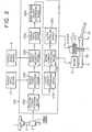
- a motor-driven power steering system having a control unit 109 constructed in accordance with one embodiment of the present invention.
- the control unit 109 is adapted to receive the output signals from a torque sensor 3, a vehicle speed sensor 10 and a vehicle height sensor 18 for controlling the operations of a motor 13 in the form of a DC motor and a clutch means 16 in the form of an electromagnetic switching clutch in a manner such that the power-assisting force transmitted from the motor 13 to the steerable road wheels (not shown) is controlled in accordance with the travelling speed of the vehicle and the steering torque imparted to the steering wheel I by the operator under the normal operating condition of the vehicle speed sensor 10, but reduced to zero if the vehicle speed sensor 10 has failed and/or an electric line or wiring connecting between the vehicle speed sensor 10 and the control unit 109 is cut or broken.
- the control unit 109 comprises: a steering torque measuring means 109a adapted to receive the output signal of the torque sensor 3 for measuring the operator-induced steering torque; a vehicle speed measuring means 109b adapted to receive the output signal of the vehicle speed sensor 10 for measuring the travelling speed of the vehicle; a vehicle height measuring means 109c adapted to receive the output signal from the vehicle height sensor 18 and generate an output signal having a variation frequency and a variation amplitude which correspond to the measured vehicle height; a vehicle travel judging means 109d adapted to receive the output signal of the vehicle height measuring means 109c and judge that the vehicle is travelling when the variation frequency and the variation amplitude of the output signal of the vehicle height measuring means 109c are greater than respective prescribed reference values for a time duration exceeding a preset period; a speed-sensor failure determining means 109e adpated to receive the output signals of the vehicle speed measuring means 109b and the vehicle travel judging means 109d and determine that there is failure in the vehicle speed sensor 10 and/
- control unit 109 acts to control the operation of the motor 13 in the form of a DC motor in the manner as illustrated in Fig. 3. More specifically, when steering torque increases in the righthand direction to point a in Fig.
- the motor 13 is turned on and supplied with an offset current of a certain low level top (for example, about 2 to 10 amperes) in order to alleviate the inertia influence from the motor 13 and the mechanical portions.
- an offset current of a certain low level top for example, about 2 to 10 amperes
- the current supplied to the motor 13 begins to increase, at point b, linearly in direct proportion to the intensity of steering torque, and reaches 100 % current at point c.
- current flowing through the motor 13 begins to decrease at point and becomes to be the offset levelloF at point b.
- the current supply to the motor 13 is reduced to zero and the motor 13 is stopped. Similar to this, the motor 13 is controlled in the same manner when the steering torque increases or decreases in the lefthand direction.
- the power-assisting torque generated by the motor 13 is in direct proportion to the current supplied thereto.
- the motor 13 is energized or turned on at point a and supplied with the offset current I QF .
- the current supplied to the motor 13 begins to gradually increase at point b so that the output torque of the motor 13 to be transmitted to the worm 14 accordingly increases gradually.
- the assisting torque having the intensity corresponding to the operator's steering effort applied to the steering wheel I is transmitted to the second rack tooth portion 6b on the steering rack 6 through the intermediary of the worm wheel 15, the electromagnetic switching clutch 16 and the second pinion 17, thereby lightening the steering operation for the operator.
- the control unit 109 controls the operations of the motor 13 and the electromagnetic switching clutch 16 in the following manner.
- the current supplied to the motor 13 is reduced to an offset current level I OF (about 2 - -10 amperes) at point d in Fig. 4 at which the vehicle speed increases to a prescribed second reference speed V 2 , held constant at the offset current level top until the vehicle speed further increases to a prescribed first reference speed level Vi at point e in Fig. 4, and reduced to zero at point e.
- I OF about 2 - -10 amperes
- the voltage imposed on the clutch 16 is held constant at 100% level until the vehicle speed increases to the first reference speed level Vi at point e, and made zero at the first reference speed level Vi so that the clutch 16 is switched off to release the mechanical connection between the worm wheel 15 and the second pinion 17, thereby making the steering operation for the operator heavier without any power assist.
- the power steering system is changed into a manual steering mode so as to avoid the above situation.
- failure in the vehicle speed sensor 10 and/or breaks in the wiring connecting the speed sensor 10 to the control unit 109 is first detected in the following manner. Namely, as illustrated in Fig. 2, the output signal of the vehicle height sensor 18 is input to the vehicle height measuring means 109c which outputs to the vehicle travel judging means 109d a vehicle height signal having a variation frequency f H and a variation amplitude A H which correspond to the measured vehicle height H.
- the vehicle travel judging means 109d judges from the vehicle height signal of the vehicle height measuring means 109c whether or not the vehicle is travelling.
- variation frequency f H and the variation amplitude A H of the vehicle height signal continue to be greater than respective prescribed reference values (for example, 0.5 Hz and ⁇ I cm) for more than a prescribed time duration (for example, 5 seconds), it is judged that the vehicle is travelling.
- respective prescribed reference values for example, 0.5 Hz and ⁇ I cm
- a prescribed time duration for example, 5 seconds
- the speed-sensor failure determining means 109e determines that there is failure in the speed sensor 18 and/or breaks in the wiring connecting between the speed sensor 18 and the control unit 109, and operates, if so determined, to make the current supplied to the motor 13 and the voltage imposed on the electromagnetic switching clutch 16 into zero, thereby changing the steering system into a non-power assisted manual steering mode.
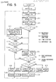
- the control unit 109 is initialized after the key or ignition switch is turned on, and then, at step SI, from the output signal of the steering torque sensor 3, the steering torque measuring means 109a measures the steering torque imparted to the steering wheel I by the operator.
- the vehicle-speed measuring means 109b measures the travelling speed V of the vehicle and generates an output signal representative of the measured vehicle speed V
- the vehicle height measuring means 109c measures the height H of the vehicle from the ground and generates a vehicle height signal having a variation frequency f H and a variation amplitude As which correspond to the measured vehicle height.
- step S4 it is determined that whether or not the measured vehicle speed V is equal to zero, and if not, the control process proceeds to step S5 where a motor current corresponding to the measured steering torque Ts is read out. Then, at step S6, it is determined whether or not the vehicle speed V is greater than a first reference speed Vi, and if V > Vi, the control process proceeds to step S15, and if V ⁇ Vi, the control process proceeds to step S7 where it is further determined whether or not the vehicle speed V is greater than a second reference speed V 2 which is smaller than the first reference speed Vi. If V > V 2 , the motor current is reduced to an offset current levelloF (for example 2 -10 ampere), and the clutch 16 is connected at step S9. At step S7, however, if V ⁇ V 2 , the control process proceeds to step SIO where the motor current 1 M corresponding to the measured steering torque Ts is output, and then the control process proceeds to step S9.
- V ⁇ V 2 the control process proceeds to step SIO where the motor current 1
- step S4 if it is judged that the vehicle speed is equal to zero, the control process proceeds to step SII where the variation frequency f H and the variation amplitude A H of the vehicle height signal H is calculated. Then, at step SI2, it is determined whether or not the calculated variation frequency f H of the vehicle height signal H is greater than a prescribed reference frequency fs, and if not, the control process proceeds to step S5 but if so, at step SI3, it is determined whether or not the calculated variation amplitude A HO f the vehicle height signal H is greater than a prescribed reference amplitude As.
- step S5 it is determined whether or not the time duration to for which the condition of f H > fs and A H > As continues is greater than a reference time ts. If t D ⁇ ts, the control process proceeds to step S5, but if to > ts, then the control process proceeds to step SI5 where the current supplied to the motor 13 is made zero, and at step SI6, the voltage imposed on the electromagnetic switching clutch 16 is also made zero thereby to disconnect the clutch 16. After steps S9 and S16, the control process returns to step SI, and the above-described operations are repeated.
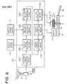
- Fig. 6 shows another embodiment of the present invention which has a different control unit 109'.
- a throttle opening sensor 18' for sensing the opening degree of an unillustrated throttle valve disposed in an unillustrated intake passage of an engine to generate an output signal representative of the detected throttle opening degree
- the control unit 109' includes, in addition to the same components as those of the previous embodiment denoted by reference numerals 109a, 109b, and 109d through 109h, a throttle opening measuring means 109i in place of the vehicle height measuring means 109c and the vehicle travel judging means 109d.
- the throttle opening measuring means 109i is adapted to receive the output signal from the throttle opening sensor 18' for measuring the opening degree So of the throttle valve.
- the speed-sensor failure determining means 109e is adapted to receive the output signals of the vehicle speed measuring means 109b and the throttle opening measuring means 109i and determine whether or not there is failure in the vehicle speed sensor 10 or breaks in the wiring connecting between the vehicle speed sensor 10 and the control unit 109'.
- the speed-sensor failure determining means 109e determines that there is failure in the speed sensor 10 and/or breaks in the wiring connecting between the speed sensor 10 and the control unit 109', and operates to make both the motor current and the clutch voltage into zero, thereby changing the steering system into a non-power assisted manual steering mode.
- Fig. 7 is the flow chart showing the control process according to the embodiment of Fig. 6.
- This flow chart is substantially similar to the flow chart of Fig. 5 except for the following. Namely, in this flow chart, the step S3 of Fig. 5 is replaced by step S3', and the steps SII through SI4 of Fig. 5 are replaced by steps SI7 and S18.
- the throttle opening measuring means 109i measures from the output signal of the throttle opening sensor 18' the opening degree So of an unillustrated throttle valve.
- step SI7 the measured opening degree So of the throttle valve is compared with a reference throttle opening Ss. If So ⁇ Ss, the control process proceeds to step S5, but if So > Ss, then at step S18, the time duration t D ' for which zero output of the vehicle speed measuring means 109b continues is compared with a reference time ts'. If t D ' ⁇ ts', the control process proceeds to step S5, but if t D ' > ts', the control process proceeds to step S15.
- the control process of this flow chart other than the above is identical to that of Fig. 5 and hence further detailed description thereof will be unnecessary.
Landscapes
- Engineering & Computer Science (AREA)
- Chemical & Material Sciences (AREA)
- Combustion & Propulsion (AREA)
- Transportation (AREA)
- Mechanical Engineering (AREA)
- Steering Control In Accordance With Driving Conditions (AREA)
- Power Steering Mechanism (AREA)
Applications Claiming Priority (4)
| Application Number | Priority Date | Filing Date | Title |
|---|---|---|---|
| JP12400986A JPH069981B2 (ja) | 1986-05-27 | 1986-05-27 | モ−タ駆動式パワ−ステアリング制御装置 |
| JP124009/86 | 1986-05-27 | ||
| JP61164161A JPS6320270A (ja) | 1986-07-11 | 1986-07-11 | モ−タ駆動式パワ−ステアリング制御装置 |
| JP164161/86 | 1986-07-11 |
Publications (3)
| Publication Number | Publication Date |
|---|---|
| EP0247863A2 true EP0247863A2 (de) | 1987-12-02 |
| EP0247863A3 EP0247863A3 (en) | 1989-07-12 |
| EP0247863B1 EP0247863B1 (de) | 1992-07-22 |
Family
ID=26460784
Family Applications (1)
| Application Number | Title | Priority Date | Filing Date |
|---|---|---|---|
| EP87304708A Expired - Lifetime EP0247863B1 (de) | 1986-05-27 | 1987-05-27 | Motorbetriebene Servolenkung für Fahrzeuge |
Country Status (4)
| Country | Link |
|---|---|
| US (1) | US4862366A (de) |
| EP (1) | EP0247863B1 (de) |
| KR (1) | KR900008031B1 (de) |
| DE (1) | DE3780516T2 (de) |
Cited By (3)
| Publication number | Priority date | Publication date | Assignee | Title |
|---|---|---|---|---|
| EP0353656A3 (en) * | 1988-07-30 | 1990-05-02 | Koyo Seiko Co., Ltd. | Electric power steering system |
| EP0340044A3 (de) * | 1988-04-28 | 1992-09-30 | Mitsubishi Denki Kabushiki Kaisha | Elektrische Servolenkungseinrichtung |
| US7824707B2 (en) | 2001-12-05 | 2010-11-02 | Lts Lohmann Therapie Systeme Ag | Transdermal therapeutic system provided with improved long-term carrying comfort |
Families Citing this family (12)
| Publication number | Priority date | Publication date | Assignee | Title |
|---|---|---|---|---|
| JPH06506B2 (ja) * | 1987-03-04 | 1994-01-05 | 三菱電機株式会社 | モ−タ駆動式パワ−ステアリング制御方法 |
| JP2641245B2 (ja) * | 1988-04-14 | 1997-08-13 | 三菱電機株式会社 | 電動式パワーステアリング装置 |
| JPH02227380A (ja) * | 1989-02-28 | 1990-09-10 | Mazda Motor Corp | 車両の後輪操舵とパワーステアリングの協調制御装置 |
| US6039132A (en) * | 1998-04-01 | 2000-03-21 | Deere & Company | Steering control system for tracked vehicle |
| DE10056133A1 (de) * | 2000-11-13 | 2002-05-23 | Zf Lenksysteme Gmbh | Elektrische Lenkvorrichtung für Kraftfahrzeuge |
| JP2004136821A (ja) * | 2002-10-18 | 2004-05-13 | Nsk Ltd | 電動パワーステアリング装置 |
| EP1966028B1 (de) | 2005-12-21 | 2013-05-15 | Volvo Trucks North America | Verbessertes servolenksystem mit elektrischer zusatzpumpe |
| JP5052640B2 (ja) * | 2010-04-16 | 2012-10-17 | 三菱電機株式会社 | パワーステアリング装置 |
| KR101724902B1 (ko) * | 2015-09-15 | 2017-04-07 | 현대자동차주식회사 | 차량의 통합형 전, 후륜 파워 조향 시스템 및 그 제어 방법 |
| US10071764B2 (en) * | 2016-11-11 | 2018-09-11 | Steering Solutions Ip Holding Corporation | Methods to control a steering system |
| CN108438046B (zh) * | 2018-03-16 | 2020-01-21 | 北京汽车股份有限公司 | 一种车辆、磁浮离合系统、电动助力转向系统及控制方法 |
| US11052940B1 (en) | 2021-03-12 | 2021-07-06 | Canoo Technologies Inc. | Steer-by-wire systems and methods of operating thereof in vehicles |
Family Cites Families (8)
| Publication number | Priority date | Publication date | Assignee | Title |
|---|---|---|---|---|
| JPS6067264A (ja) * | 1983-09-24 | 1985-04-17 | Jidosha Kiki Co Ltd | 動力舵取装置 |
| JPS60166560A (ja) * | 1984-02-10 | 1985-08-29 | Jidosha Kiki Co Ltd | 動力舵取装置の制御装置 |
| US4573545A (en) * | 1984-08-30 | 1986-03-04 | Eaton Corporation | Fail-safe device for an electrical power assisted steering system including an in-line clutch mechanism |
| EP0174137A3 (de) * | 1984-08-30 | 1987-07-15 | Eaton Corporation | Sicherheitsmechanismus für ein elektrisches Servolenkungssystem |
| FR2577878B1 (fr) * | 1985-02-26 | 1989-03-31 | Honda Motor Co Ltd | Dispositif de direction assiste par un moteur |
| CA1280375C (en) * | 1986-01-14 | 1991-02-19 | Yasuo Shimizu | Motor-driven power steering system for vehicles |
| JPH0798490B2 (ja) * | 1986-02-06 | 1995-10-25 | 本田技研工業株式会社 | 電動式パワーステアリング装置 |
| JPH0624953B2 (ja) * | 1986-04-08 | 1994-04-06 | 本田技研工業株式会社 | 電動式パワ−ステアリング装置 |
-
1987
- 1987-03-21 KR KR1019870002580A patent/KR900008031B1/ko not_active Expired
- 1987-05-27 DE DE8787304708T patent/DE3780516T2/de not_active Expired - Fee Related
- 1987-05-27 US US07/054,773 patent/US4862366A/en not_active Expired - Fee Related
- 1987-05-27 EP EP87304708A patent/EP0247863B1/de not_active Expired - Lifetime
Cited By (8)
| Publication number | Priority date | Publication date | Assignee | Title |
|---|---|---|---|---|
| EP0340044A3 (de) * | 1988-04-28 | 1992-09-30 | Mitsubishi Denki Kabushiki Kaisha | Elektrische Servolenkungseinrichtung |
| EP0590697A1 (de) * | 1988-04-28 | 1994-04-06 | Mitsubishi Denki Kabushiki Kaisha | Elektrische Servolenkeinrichtung |
| EP0353656A3 (en) * | 1988-07-30 | 1990-05-02 | Koyo Seiko Co., Ltd. | Electric power steering system |
| US7824707B2 (en) | 2001-12-05 | 2010-11-02 | Lts Lohmann Therapie Systeme Ag | Transdermal therapeutic system provided with improved long-term carrying comfort |
| US8628795B2 (en) | 2001-12-05 | 2014-01-14 | Lts Lohmann Therapie-Systeme Ag | Transdermal therapeutic buprenorphine system |
| US8883198B2 (en) | 2001-12-05 | 2014-11-11 | Lts Lohmann Therapie Systeme Ag | Transdermal rivastigmine therapeutic system |
| US9101605B2 (en) | 2001-12-05 | 2015-08-11 | Lts Lohmann Therapie Systeme Ag | Buprenorphine transdermal therapeutic system and method of administering |
| US9616045B2 (en) | 2001-12-05 | 2017-04-11 | Lts Lohmann Therapie-Systeme Ag | Transdermal therapeutic system having improved long-term wearing comfort |
Also Published As
| Publication number | Publication date |
|---|---|
| US4862366A (en) | 1989-08-29 |
| KR870010995A (ko) | 1987-12-19 |
| EP0247863A3 (en) | 1989-07-12 |
| DE3780516D1 (de) | 1992-08-27 |
| KR900008031B1 (ko) | 1990-10-31 |
| EP0247863B1 (de) | 1992-07-22 |
| DE3780516T2 (de) | 1993-03-04 |
Similar Documents
| Publication | Publication Date | Title |
|---|---|---|
| EP0249506B1 (de) | Motorbetriebene Servolenkung für Fahrzeuge | |
| EP0343693B1 (de) | Von einem Motor angetriebene Servolenkung für ein Fahrzeug | |
| EP0247863A2 (de) | Motorbetriebene Servolenkung für Fahrzeuge | |
| US5999870A (en) | Motor-driven power steering system for a vehicle and a method for controlling same | |
| EP0243181B1 (de) | Servolenkeinrichtung für Kraftfahrzeuge | |
| EP0361726B1 (de) | Servomotorlenkeinrichtung | |
| KR900001850B1 (ko) | 모터구동식 동력조향시스템 | |
| KR960005848B1 (ko) | 전동파워 스티어링 제어장치 및 방법 | |
| US4754828A (en) | Motor-driven power steering system for a vehicle | |
| US5039926A (en) | Motorized power steering apparatus | |
| US5341891A (en) | Motor-driven power steering apparatus and method | |
| US4849889A (en) | Motor-driven power steering system for a vehicle | |
| KR940004681B1 (ko) | 모터구동식 파워스테어링 제어장치 | |
| EP0274116B1 (de) | Servolenkungs-Steuerungseinrichtung | |
| US4754830A (en) | Motor-driven power steering system for a vehicle | |
| KR900001849B1 (ko) | 모터구동식 동력조향 제어방법 | |
| EP0273387B1 (de) | Servolenkungs-Steuerungseinrichtung | |
| JP2641243B2 (ja) | 電動式パワーステアリング装置 | |
| JPS6320270A (ja) | モ−タ駆動式パワ−ステアリング制御装置 | |
| JPH05319296A (ja) | モータ駆動式パワーステアリング制御装置 | |
| JPH069981B2 (ja) | モ−タ駆動式パワ−ステアリング制御装置 | |
| JPH05124525A (ja) | 電動式パワーステアリング制御装置 | |
| JPH069970B2 (ja) | モ−タ駆動式パワ−ステアリング制御装置 |
Legal Events
| Date | Code | Title | Description |
|---|---|---|---|
| PUAI | Public reference made under article 153(3) epc to a published international application that has entered the european phase |
Free format text: ORIGINAL CODE: 0009012 |
|
| AK | Designated contracting states |
Kind code of ref document: A2 Designated state(s): DE FR GB |
|
| PUAL | Search report despatched |
Free format text: ORIGINAL CODE: 0009013 |
|
| AK | Designated contracting states |
Kind code of ref document: A3 Designated state(s): DE FR GB |
|
| 17P | Request for examination filed |
Effective date: 19890829 |
|
| 17Q | First examination report despatched |
Effective date: 19901203 |
|
| GRAA | (expected) grant |
Free format text: ORIGINAL CODE: 0009210 |
|
| AK | Designated contracting states |
Kind code of ref document: B1 Designated state(s): DE FR GB |
|
| REF | Corresponds to: |
Ref document number: 3780516 Country of ref document: DE Date of ref document: 19920827 |
|
| REG | Reference to a national code |
Ref country code: GB Ref legal event code: 727 |
|
| REG | Reference to a national code |
Ref country code: GB Ref legal event code: 727A |
|
| ET | Fr: translation filed | ||
| REG | Reference to a national code |
Ref country code: GB Ref legal event code: 727B |
|
| REG | Reference to a national code |
Ref country code: GB Ref legal event code: SP |
|
| PLBE | No opposition filed within time limit |
Free format text: ORIGINAL CODE: 0009261 |
|
| STAA | Information on the status of an ep patent application or granted ep patent |
Free format text: STATUS: NO OPPOSITION FILED WITHIN TIME LIMIT |
|
| 26N | No opposition filed | ||
| PGFP | Annual fee paid to national office [announced via postgrant information from national office to epo] |
Ref country code: FR Payment date: 19950510 Year of fee payment: 9 |
|
| PGFP | Annual fee paid to national office [announced via postgrant information from national office to epo] |
Ref country code: GB Payment date: 19950516 Year of fee payment: 9 |
|
| PGFP | Annual fee paid to national office [announced via postgrant information from national office to epo] |
Ref country code: DE Payment date: 19950523 Year of fee payment: 9 |
|
| PG25 | Lapsed in a contracting state [announced via postgrant information from national office to epo] |
Ref country code: GB Effective date: 19960527 |
|
| GBPC | Gb: european patent ceased through non-payment of renewal fee |
Effective date: 19960527 |
|
| PG25 | Lapsed in a contracting state [announced via postgrant information from national office to epo] |
Ref country code: FR Effective date: 19970131 |
|
| PG25 | Lapsed in a contracting state [announced via postgrant information from national office to epo] |
Ref country code: DE Effective date: 19970201 |
|
| REG | Reference to a national code |
Ref country code: FR Ref legal event code: ST |