EP0247879A2 - Boîte pliable pour compresseur de déchets - Google Patents
Boîte pliable pour compresseur de déchets Download PDFInfo
- Publication number
- EP0247879A2 EP0247879A2 EP87304743A EP87304743A EP0247879A2 EP 0247879 A2 EP0247879 A2 EP 0247879A2 EP 87304743 A EP87304743 A EP 87304743A EP 87304743 A EP87304743 A EP 87304743A EP 0247879 A2 EP0247879 A2 EP 0247879A2
- Authority
- EP
- European Patent Office
- Prior art keywords
- box
- panels
- panel
- bottom panel
- trash
- Prior art date
- Legal status (The legal status is an assumption and is not a legal conclusion. Google has not performed a legal analysis and makes no representation as to the accuracy of the status listed.)
- Granted
Links
Images


Classifications
-
- B—PERFORMING OPERATIONS; TRANSPORTING
- B65—CONVEYING; PACKING; STORING; HANDLING THIN OR FILAMENTARY MATERIAL
- B65F—GATHERING OR REMOVAL OF DOMESTIC OR LIKE REFUSE
- B65F9/00—Transferring of refuse between vehicles or containers with intermediate storage or pressing
-
- B—PERFORMING OPERATIONS; TRANSPORTING
- B30—PRESSES
- B30B—PRESSES IN GENERAL
- B30B9/00—Presses specially adapted for particular purposes
- B30B9/30—Presses specially adapted for particular purposes for baling; Compression boxes therefor
- B30B9/3003—Details
-
- B—PERFORMING OPERATIONS; TRANSPORTING
- B30—PRESSES
- B30B—PRESSES IN GENERAL
- B30B9/00—Presses specially adapted for particular purposes
- B30B9/30—Presses specially adapted for particular purposes for baling; Compression boxes therefor
- B30B9/3003—Details
- B30B9/3032—Press boxes
-
- B—PERFORMING OPERATIONS; TRANSPORTING
- B30—PRESSES
- B30B—PRESSES IN GENERAL
- B30B9/00—Presses specially adapted for particular purposes
- B30B9/30—Presses specially adapted for particular purposes for baling; Compression boxes therefor
- B30B9/3057—Fluid-driven presses
-
- B—PERFORMING OPERATIONS; TRANSPORTING
- B65—CONVEYING; PACKING; STORING; HANDLING THIN OR FILAMENTARY MATERIAL
- B65D—CONTAINERS FOR STORAGE OR TRANSPORT OF ARTICLES OR MATERIALS, e.g. BAGS, BARRELS, BOTTLES, BOXES, CANS, CARTONS, CRATES, DRUMS, JARS, TANKS, HOPPERS, FORWARDING CONTAINERS; ACCESSORIES, CLOSURES, OR FITTINGS THEREFOR; PACKAGING ELEMENTS; PACKAGES
- B65D5/00—Rigid or semi-rigid containers of polygonal cross-section, e.g. boxes, cartons or trays, formed by folding or erecting one or more blanks made of paper
- B65D5/32—Rigid or semi-rigid containers of polygonal cross-section, e.g. boxes, cartons or trays, formed by folding or erecting one or more blanks made of paper having bodies formed by folding and interconnecting two or more blanks
- B65D5/322—Rigid or semi-rigid containers of polygonal cross-section, e.g. boxes, cartons or trays, formed by folding or erecting one or more blanks made of paper having bodies formed by folding and interconnecting two or more blanks at least one container body part formed by folding a single blank to essentially U-shape with or without extensions which form openable lid elements
- B65D5/323—Rigid or semi-rigid containers of polygonal cross-section, e.g. boxes, cartons or trays, formed by folding or erecting one or more blanks made of paper having bodies formed by folding and interconnecting two or more blanks at least one container body part formed by folding a single blank to essentially U-shape with or without extensions which form openable lid elements and two further opposed body panels formed from two essentially planar blanks
-
- B—PERFORMING OPERATIONS; TRANSPORTING
- B65—CONVEYING; PACKING; STORING; HANDLING THIN OR FILAMENTARY MATERIAL
- B65D—CONTAINERS FOR STORAGE OR TRANSPORT OF ARTICLES OR MATERIALS, e.g. BAGS, BARRELS, BOTTLES, BOXES, CANS, CARTONS, CRATES, DRUMS, JARS, TANKS, HOPPERS, FORWARDING CONTAINERS; ACCESSORIES, CLOSURES, OR FITTINGS THEREFOR; PACKAGING ELEMENTS; PACKAGES
- B65D5/00—Rigid or semi-rigid containers of polygonal cross-section, e.g. boxes, cartons or trays, formed by folding or erecting one or more blanks made of paper
- B65D5/36—Rigid or semi-rigid containers of polygonal cross-section, e.g. boxes, cartons or trays, formed by folding or erecting one or more blanks made of paper specially constructed to allow collapsing and re-erecting without disengagement of side or bottom connections
-
- B—PERFORMING OPERATIONS; TRANSPORTING
- B65—CONVEYING; PACKING; STORING; HANDLING THIN OR FILAMENTARY MATERIAL
- B65F—GATHERING OR REMOVAL OF DOMESTIC OR LIKE REFUSE
- B65F1/00—Refuse receptacles; Accessories therefor
- B65F1/14—Other constructional features; Accessories
- B65F1/1405—Compressing means incorporated in, or specially adapted for, refuse receptacles
-
- Y—GENERAL TAGGING OF NEW TECHNOLOGICAL DEVELOPMENTS; GENERAL TAGGING OF CROSS-SECTIONAL TECHNOLOGIES SPANNING OVER SEVERAL SECTIONS OF THE IPC; TECHNICAL SUBJECTS COVERED BY FORMER USPC CROSS-REFERENCE ART COLLECTIONS [XRACs] AND DIGESTS
- Y10—TECHNICAL SUBJECTS COVERED BY FORMER USPC
- Y10S—TECHNICAL SUBJECTS COVERED BY FORMER USPC CROSS-REFERENCE ART COLLECTIONS [XRACs] AND DIGESTS
- Y10S229/00—Envelopes, wrappers, and paperboard boxes
- Y10S229/907—Trash box
Definitions
- This invention generally relates to a trash compactor system and particularly a collapsible box suitable for use in an aircraft trash compactor system.
- Cardboard or fiberboard boxes have been found to provide suitable strength to withstand the high compacting pressures characteristic of commercial and aircraft compactors, but there has been a considerable difficulty in designing a collapsible box which can be easily opened up and placed in the trash compactor chamber so that the box is properly aligned with the compacting piston or platen.
- Collapsible cardboard and fiberboard boxes have a tendency when opened up to spring back to a slightly closed condition. As a result of this tendency to take a slightly closed position when the trash boxes are placed within the compacting chamber of the compactor, the box will not be properly aligned with respect to the compacting platen of the compactor. On the down or compacting stroke of the platen it will frequently engage the sides of the trash box severely damaging the container and limiting the usefulness thereof.
- a substantial need remains for a collapsible box which can be stored in a flattened condition and which can be easily opened up and inserted into a trash compactor so that the box is properly aligned within the compacting chamber.
- a cardboard or fiberboard box which does not readily leak fluid when fluid-containing trash is compacted therein.
- the present invention provides a collapsible box, comprising: an integrally formed elongate main section with a rectangularly shaped bottom panel and upstanding, rectangularly shaped front and rear panels hingedly connected to the front and rear margins respectively of the bottom panel; a pair of continuous, inwardly folding flanges integrally formed with the main section and each extending along the long sides thereof; a pair of upstanding side panels secured to the inner sides of the continuous inwardly folding flanges; and a continuous, centrally located medial fold line extending along the length of the main section including the front, rear and bottom panels to facilitate the folding of the box into a flattened state.
- both of the front and the rear panels are provided with a pair of diagonal fold lines extending from the lower corners of the panels at the junction with the margin of the bottom panel to a common point on the medial fold line on the respective panels.
- This construction allows the front and rear panels to fold inwardly about the medial fold line and the bottom panel to fold outwardly about the medial fold line when the box is collapsed into a flattened condition for storage.
- the bottom panel is provided with two pairs of diagonal fold lines which extend from adjacent corners of the panel to common points on the medial fold line of the panel. This construction allows the bottom panel to fold inwardly about the medial fold line and the front and rear panels to fold outwardly about the medial fold line thereof when the box is collapsed into a flattened condition for storage.
- each of the lower portions of the flange sections which are hingedly connected to the side margins of the front and rear panels are provided with a pair of fold lines which originate at the corner intersection of these panels with the corners of the bottom panel to define triangularly shaped flange segments which are folded over onto adjacent portions of the same flange section when the front and rear panels are folded in an upright position with respect to the bottom panel.
- the exposed face of the triangularly shaped segment is secured by suitable adhesive to the flange section connected to the side margin of the bottom panel.
- At least one of the side panels of the box is provided with a free-standing edge which is adapted to fit under or into a guide or securing element or overhang provided on the inside wall of the compacting chamber of the trash compactor to fix the position of the one side of the opened box therein.
- This embodiment is particularly suitable with the preferred box construction wherein the front and rear panels of the trash box fold inwardly about the medial fold line.
- the box is completely open and properly aligned with respect to the platen so that there is little chance of the platen contacting the upstanding panels of the box during compaction. Moreover, with the trash box completely open, there is less chance of trash falling between the box and the chamber walls.
- Closure flaps which are preferably provided along the outside of the compactor box, are folded over the top thereof to facilitate closing and may be taped, glued, or otherwise secured in a closed position to enable the trash compactor box to be transported to another area for disposal without loss of its contents.
- the invention also provides a trash compacting system which includes a trash compactor having a compacting chamber and a vertically reciprocating compacting platen adapted to compact trash in a trash container disposed in the compacting chamber, the trash container comprising a collapsible, rectangularly shaped box having a free-standing extension along one side panel thereof which is seated in an overhang or guide means disposed along one wall of the compacting chamber to thereby position the box panel with the compacting chamber.
- the trash compactor 10 generally comprises a housing or cabinet 11 which has a control panel 12, a chute 13 for feeding trash into the compacting chamber 14 in the housing 11 and a door 15 in the front of the housing 11 to facilitate loading and unloading trash compactor containers or boxes 16.
- the door 15 is provided with a latch 17 for opening and closing thereof.
- the particular embodiment shown in Figures 1 and 2 is designed to be portable and is provided with wheels 18 on the lower portion thereof and with a handle 19 to facilitate moving the compactor 10 to desired locations.
- the door 15 on the front of the cabinet 11 is pivotally mounted along one side thereof by means of hinges (not shown) in order to install and remove trash containers 16.
- suitable interlocks are provided on the chute 13 and the door 15 to ensure that the compactor 10 is inoperable unless both the door 15 and chute 13 are closed.
- a preferred embodiment of the trash compactor box 16 illustrated in detail in Figures 3, 4 and 5, generally comprises a main section 20 with integrally formed front panel 21, rear panel 22, bottom panel 23 and opposing side panels 24 and 25.
- the front panel 21, rear panel 22 and side panels 24 and 25 are each provided with closure flaps 26, 27, 28 and 29, respectively, to faciliate closing the box after use thereof.
- the main section 20 of the box 16 is provided with a pair of continuous, inwardly folding flanges which are formed integrally with and hingedly connected to the sides of the front panel 21, rear panel 22 and bottom panel 23. Side panels 24 and 25 are secured, usually by an adhesive, to the inner sides of flanges 30.
- the blanks from which the trash compactor box 16 is constructed is illustrated in Figure 5.
- the main section 20 is a single piece of cardboard, fiberboard, or other suitable material.
- the front panel 21 is hingedly connected to the bottom panel 23 through a fold 32.
- the rear panel 22 is similarly hingedly connected to the bottom panel 23 by means of a fold 33.
- the inwardly folding, continuous flanges 30 are integral parts of the one-piece main section 20 and each flange comprises sections 32, 35 and 36 which are hingedly connected to the front panel 21, rear panel 22 and bottom panel 23, respectively, by means of seamless folds 40, 41 and 42 respectively.
- Each of the flange sections 34 and 35 connected to the front and rear panels 21 and 22 is provided on the lower section thereof, adjacent to the bottom panel 23, with a pair of folds 43 and 44 which originate at the corners of the bottom panel 23 and extend outwardly to the edge of the flange section.
- Fold 43 extends transversely and fold 44 extends diagonally to define a triangularly shaped segment 45 which, when the panels 21 and 22 are folded upright to construct the box, folds about the diagonal line 44 to face the adjacent area of the same flange section.
- segments 45 are then folded about fold line 43 so they can be secured by suitable means such as by an adhesive to the outside flange section 36 connected to the bottom panel 23.
- a continuous, seamless junction is thereby formed between the margins of the bottom panel 23 and the front, rear, and side flanges and the corners therebetween to minimize fluid leakage during the compacting process.
- a continuous medial fold line 50 is provided along the entire length of the elongated main section 30, crossing the front, rear and bottom panels 21, 22 and 23, respectively.
- a pair of diagonal fold lines 51 and 52 are provided on each of the front and rear panels 21 and 22 which extend from the lower corners of the panels to a common point on the medial fold line 50 on each of the panels.
- the assembled box 16 is shown in partially opened state in Figure 4.
- the inwardly folded front panel 21 and the rear panel 22 are pushed inwardly at corners where the medial fold lines 50 are located, as indicated by the arrows, to force the front and rear panels 21 and 22 to open completely and thereby force the side panels 24 and 25 outwardly.
- the box 16 is placed within the trash compactor chamber 14 as shown in Figure 2, there is a tendency for the front and rear panels 21 and 22 to remain folded slightly inwardly.
- the rear panel is pushed against the rear wall 60 (shown in Figure 6) to thereby fully open the rear panel and when the door 15 is closed, the inside surface of the door 15 urges the front panel 21 ot a fully open position.
- At least one of the side panels of the box 16 is provided with a free-standing edge 56 which is adapted to be seated in the guide or securing element 57 on the wall of the compacting chamber 14. In this manner, the box 16 is properly aligned within the compacting chamber 14 to avoid contact with the downwardly moving compacting platen 55 during compaction, as shown in Figure 6. If desired, the free-standing edge 56 may be part of the closure flap 29.
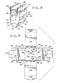
- FIGs 8 and 9 An alternative embodiment of the trash compactor box is shown in Figures 8 and 9.
- the box 70 of this embodiment is formed from blanks having essentially the same outline as those shown in Figure 5 for the box 16. The only difference is the location of the fold lines.
- the bottom panel 23 is provided with two pairs of fold lines 72 and 73 and 74 and 75. Each pair of fold lines extends from the corners of the bottom panel 23 to a common point on the medial fold line 50. No diagonal fold lines are provided on the front panel 21 and rear panel 22. This construction allows the bottom panel 23 to fold inwardly (downwardly) about the medial fold line 50 and the front panel 21 and rear panel 22 to fold outwardly about the medial fold line 50, as shown in Figure 8.
- the boxes 16 and 70 generally are assembled in the same manner.
- the side panels 24 and 25 are first secured by adhesive or other suitable means to the inside of flange sections 36 which are attached to the side margins of the bottom panel 23, the side panels are raised to an upright position by folding the flange section 36 about line 42.
- the front panel 21 and rear panel 22 are then folded upwardly about fold lines 32 and 33, respectively, and flange sections 35 and 36 attached to the side margins of these panels are secured to the outside of side panel 24 and 25 by suitable adhesive or other means.
- front and rear panels 21 and 22 are folded into an upright position and the flange sections 34 and 35 are glued to the side panels 24 and 25.
- the triangularly shaped portion 45 of the flange sections 34 and 35 extends outwardly and must be secured to the outside of the flange section 36.
- closure flaps 26-29 are preferably folded downwardly and secured against the outside of the front, rear and side panels by a small amount of adhesive so that when the box 16 or 70 is to be closed, the closure flaps can be easily pulled away from these panels with very little damage thereto.
- the completely assembled boxes 16 and 70 collapse by pressing the side panels 24 and 25 together.
- the front and rear panels 21 and 22 fold outwardly about medial fold line 50 and the bottom panel 23 folds inwardly (upwardly) about medial fold line 54, whereby when box 70 is collapsed the front and rear panels 21 and 22 fold inwardly about medial fold line 50 and bottom panel 23 fold outwardly (downwardly) about medial fold line 50.
- the opened trash containers 16 and 70 are placed within the compacting chamber with the free-standing edge 56 thereof interfitting the overhanging guide or securing means 57 on chamber wall 58, as shown in Figures 2 and 3.
- the front and rear panels 21 and 22 are pushed inwardly when the compactor door 18 is closed to ensure that the box is completely open and that it fills the chamber 14 completely and is properly aligned with the platen 55.
- another guide means can be mounted on the chamber wall opposite chamber wall 58.
- box 70 With box 70, folded corners of the outwardly folding front and rear panels 21 and 22 must be pushed outwardly and the bottom panel 23 pushed upwardly to open the box.
- the bottom panel 23 is pushed upwardly by the bottom 76 of the chamber 14. Additional means may be provided on the inside of the door 15 and the back wall 60 of the chamber 14 to ensure that the front and rear panels 21 and 22 do not fold outwardly (the folded corner moves inwardly) and interfere with the stroke of the compactor platen 55.
- the trash compactor 10 is actuated by pressing switch 77 on the control panel 12. This actuates the downward compacting stroke of the platen 55. Upon the completion of the stroke or whenever a predetermined maximum pressure is reached, the platen 55 withdraws.
- the compactor door 15 Upon completion of compaction, the compactor door 15 is opened by actuating latch 17, the trash box 16 or 70 removed and a new one replaced in the chamber 15.
- the closure flaps 26-29 which are usually lightly glued to the sides of the box, are pulled away therefrom and folded over the top of the box where they are secured by tape adhesive, or the like for subsequent disposal.
- side panels 24 and 25 are described herein as separate panels which are secured by adhesive to the inside of flanges 36, it is obvious that the side panels may be integral extensions of the flanges 36, i.e., the entire box could be made from a single piece of cardboard, fiberboard, or other suitable material.
Landscapes
- Engineering & Computer Science (AREA)
- Mechanical Engineering (AREA)
- Refuse Receptacles (AREA)
- Cartons (AREA)
- Processing Of Solid Wastes (AREA)
Applications Claiming Priority (2)
| Application Number | Priority Date | Filing Date | Title |
|---|---|---|---|
| US06/868,131 US4711390A (en) | 1984-07-27 | 1986-05-28 | Collapsible box for trash compacting system |
| US868131 | 1986-05-28 |
Publications (3)
| Publication Number | Publication Date |
|---|---|
| EP0247879A2 true EP0247879A2 (fr) | 1987-12-02 |
| EP0247879A3 EP0247879A3 (en) | 1990-04-25 |
| EP0247879B1 EP0247879B1 (fr) | 1992-07-15 |
Family
ID=25351128
Family Applications (1)
| Application Number | Title | Priority Date | Filing Date |
|---|---|---|---|
| EP87304743A Expired - Lifetime EP0247879B1 (fr) | 1986-05-28 | 1987-05-28 | Boîte pliable pour compresseur de déchets |
Country Status (8)
| Country | Link |
|---|---|
| US (1) | US4711390A (fr) |
| EP (1) | EP0247879B1 (fr) |
| JP (1) | JPS63139801A (fr) |
| KR (1) | KR950011155B1 (fr) |
| AU (1) | AU7366087A (fr) |
| CA (1) | CA1329181C (fr) |
| DE (1) | DE3780358T2 (fr) |
| IL (1) | IL82693A (fr) |
Cited By (2)
| Publication number | Priority date | Publication date | Assignee | Title |
|---|---|---|---|---|
| EP2563581A1 (fr) * | 2010-04-26 | 2013-03-06 | MAG Aerospace Industries, Inc. | Composants de compacteur d'ordure et méthodes associées |
| IT201600101331A1 (it) * | 2016-10-10 | 2018-04-10 | Iacobucci Hf Aerospace S P A | Carrello compattatore per usi aeronautici |
Families Citing this family (36)
| Publication number | Priority date | Publication date | Assignee | Title |
|---|---|---|---|---|
| FR2631311B1 (fr) * | 1988-05-16 | 1990-09-21 | Caruelle | Recipient en carton pour compactage |
| US5305949A (en) * | 1991-12-24 | 1994-04-26 | Linden Gerald E | Foldable, easily-disposable pizza box, and methods of making and using same |
| DK170503B1 (da) * | 1992-02-20 | 1995-10-02 | All Ways Aps | Åben beholder eller drikkebæger, der er fladt sammenfoldet før brug |
| DE4222712C1 (fr) * | 1992-07-10 | 1993-06-17 | Polymer-Synthese-Werk Gmbh, 4134 Rheinberg, De | |
| US5465660A (en) * | 1994-02-16 | 1995-11-14 | Aero-Design Technology | Aircraft trash collection and compacting apparatus |
| ES2190840B1 (es) * | 2000-04-10 | 2005-06-16 | Francisco J. Montserrat Garcia | Sistema reductor de volumen para residuos solidos urbanos. |
| ES2204235B1 (es) * | 2001-05-09 | 2005-04-01 | Juan Cabello Lopez | Cubo reciclable para recogida de residuos. |
| DE10255071B4 (de) * | 2002-11-25 | 2007-04-12 | Polymer-Synthese-Werk Gmbh | Transportbehälter |
| US7637417B2 (en) * | 2005-10-19 | 2009-12-29 | Fite Iv Francis Bartow | Foldable utensil set |
| GB0525558D0 (en) * | 2005-12-15 | 2006-01-25 | Ds Smith Packaging Ltd | Multi-part packaging carton |
| US20070152029A1 (en) * | 2005-12-30 | 2007-07-05 | Gardner Jeffrey M | Two piece bliss container with flap closure |
| ES1063778Y (es) * | 2006-09-19 | 2007-03-01 | Mordechai Kleiner | Caja de embalaje |
| US7487904B2 (en) * | 2007-03-30 | 2009-02-10 | International Paper Co. | Reusable pop-up container and associated container blank |
| US8839715B2 (en) | 2010-04-26 | 2014-09-23 | Mag Aerospace Industries, Llc | Trash compactor main door interlock |
| WO2013016254A1 (fr) | 2011-07-27 | 2013-01-31 | Mag Aerospace Industries, Inc. | Boîte auto-hermétique pour compacteurs de déchets |
| WO2013070844A1 (fr) * | 2011-11-08 | 2013-05-16 | Mag Aerospace Industries, Inc. | Carton de compacteur de déchets ayant des propriétés antimicrobiennes |
| US10583977B2 (en) | 2016-08-16 | 2020-03-10 | Mp Global Products, L.L.C. | Method of making an insulation material and an insulated mailer |
| US10442600B2 (en) | 2017-04-07 | 2019-10-15 | Pratt Retail Specialties, Llc | Insulated bag |
| US10800595B2 (en) | 2017-04-07 | 2020-10-13 | Pratt Retail Specialties, Llc | Box liner |
| US10954057B2 (en) | 2017-05-09 | 2021-03-23 | Pratt Retail Specialties, Llc | Insulated box |
| US10604304B2 (en) | 2017-05-09 | 2020-03-31 | Pratt Retail Specialties, Llc | Insulated bag with handles |
| US10551110B2 (en) | 2017-07-31 | 2020-02-04 | Pratt Retail Specialties, Llc | Modular box assembly |
| US10947025B2 (en) | 2017-12-18 | 2021-03-16 | Pratt Corrugated Holdings, Inc. | Insulated block packaging assembly |
| US10507968B2 (en) | 2017-12-18 | 2019-12-17 | Pratt Retail Specialties, Llc | Modular box assembly |
| CN111891589A (zh) * | 2018-04-02 | 2020-11-06 | 合肥工业大学 | 一种用于航天的物件夹持组件 |
| US11059652B2 (en) | 2018-05-24 | 2021-07-13 | Pratt Corrugated Holdings, Inc. | Liner |
| US20200115097A1 (en) * | 2018-10-10 | 2020-04-16 | International Paper Company | Leak resistant feature for bliss box |
| US10858141B2 (en) | 2018-11-13 | 2020-12-08 | Pratt Retail Specialties, Llc | Insulated box assembly with overlapping panels |
| US11066228B2 (en) | 2018-11-13 | 2021-07-20 | Pratt Retail Specialties, Llc | Insulated box assembly and temperature-regulating lid therefor |
| US11027875B2 (en) | 2019-05-02 | 2021-06-08 | Pratt Retail Specialties, Llc | Telescoping insulated boxes |
| US10882684B2 (en) | 2019-05-02 | 2021-01-05 | Pratt Retail Specialties, Llc | Box defining walls with insulation cavities |
| US11230404B2 (en) * | 2019-11-26 | 2022-01-25 | Pratt Corrugated Holdings, Inc. | Perforated collapsible box |
| US11718464B2 (en) | 2020-05-05 | 2023-08-08 | Pratt Retail Specialties, Llc | Hinged wrap insulated container |
| CN113320857B (zh) * | 2020-07-27 | 2023-02-14 | 浙江联运知慧科技有限公司 | 再生资源分类压缩回收箱 |
| USD968950S1 (en) | 2020-08-10 | 2022-11-08 | Pratt Corrugated Holdings, Inc. | Perforated collapsible box |
| US12270153B2 (en) | 2021-02-11 | 2025-04-08 | Pratt Corrugated Holdings, Inc. | Starch-cellulose composite material |
Family Cites Families (15)
| Publication number | Priority date | Publication date | Assignee | Title |
|---|---|---|---|---|
| US284179A (en) * | 1883-09-04 | Joseph p | ||
| US715026A (en) * | 1901-06-11 | 1902-12-02 | Charles H Sprague | Collapsible box. |
| US1374473A (en) * | 1920-01-22 | 1921-04-12 | A O Crawford Co Inc | Collapsible box |
| GB302849A (en) * | 1928-03-27 | 1928-12-27 | Rowland Hunt | Folding boxes and cartons |
| US2281165A (en) * | 1940-07-25 | 1942-04-28 | William W Miller | Carton |
| US2582502A (en) * | 1946-10-01 | 1952-01-15 | Raymond J Nagler | Flap holder |
| US2861735A (en) * | 1956-06-04 | 1958-11-25 | William G Faltin | Bag-like receptacle |
| US3373919A (en) * | 1964-07-22 | 1968-03-19 | Owens Illinois Inc | Composite package |
| US3334802A (en) * | 1965-07-26 | 1967-08-08 | Ex Cell O Corp | Plastic container construction |
| US3439866A (en) * | 1967-11-08 | 1969-04-22 | Hesser Ag Maschf | Packaging bag |
| US3850362A (en) * | 1972-10-13 | 1974-11-26 | Crown Zellerbach Corp | Container construction and method therefor |
| US3903790A (en) * | 1974-10-16 | 1975-09-09 | Floyd R Gladwin | Trash compactor |
| GB1571991A (en) * | 1977-01-14 | 1980-07-23 | Drg Uk Ltd | Collapsible container |
| US4300716A (en) * | 1980-01-21 | 1981-11-17 | Pneumatic Scale Corporation | Paperboard carton |
| US4620479A (en) * | 1984-07-27 | 1986-11-04 | A.K.G.S. Partnership | Aircraft trash compactor and box therefor |
-
1986
- 1986-05-28 US US06/868,131 patent/US4711390A/en not_active Expired - Lifetime
-
1987
- 1987-05-27 CA CA000538166A patent/CA1329181C/fr not_active Expired - Lifetime
- 1987-05-28 KR KR1019870005310A patent/KR950011155B1/ko not_active Expired - Lifetime
- 1987-05-28 IL IL82693A patent/IL82693A/xx not_active IP Right Cessation
- 1987-05-28 JP JP62130024A patent/JPS63139801A/ja active Pending
- 1987-05-28 EP EP87304743A patent/EP0247879B1/fr not_active Expired - Lifetime
- 1987-05-28 AU AU73660/87A patent/AU7366087A/en not_active Abandoned
- 1987-05-28 DE DE8787304743T patent/DE3780358T2/de not_active Expired - Lifetime
Cited By (4)
| Publication number | Priority date | Publication date | Assignee | Title |
|---|---|---|---|---|
| EP2563581A1 (fr) * | 2010-04-26 | 2013-03-06 | MAG Aerospace Industries, Inc. | Composants de compacteur d'ordure et méthodes associées |
| IT201600101331A1 (it) * | 2016-10-10 | 2018-04-10 | Iacobucci Hf Aerospace S P A | Carrello compattatore per usi aeronautici |
| WO2018069802A1 (fr) * | 2016-10-10 | 2018-04-19 | Iacobucci Hf Aerospace S.P.A. | Chariot compacteur pour applications aéronautiques |
| US11021252B2 (en) | 2016-10-10 | 2021-06-01 | Iacobucci Hf Aerospace S.P.A. | Compactor trolley for aeronautical applications |
Also Published As
| Publication number | Publication date |
|---|---|
| EP0247879B1 (fr) | 1992-07-15 |
| CA1329181C (fr) | 1994-05-03 |
| EP0247879A3 (en) | 1990-04-25 |
| JPS63139801A (ja) | 1988-06-11 |
| IL82693A (en) | 1992-02-16 |
| AU7366087A (en) | 1987-12-03 |
| KR950011155B1 (ko) | 1995-09-28 |
| DE3780358T2 (de) | 1992-12-17 |
| IL82693A0 (en) | 1987-11-30 |
| DE3780358D1 (de) | 1992-08-20 |
| KR870011012A (ko) | 1987-12-19 |
| US4711390A (en) | 1987-12-08 |
Similar Documents
| Publication | Publication Date | Title |
|---|---|---|
| EP0247879B1 (fr) | Boîte pliable pour compresseur de déchets | |
| US3438562A (en) | Container | |
| US2698124A (en) | Shipping and service container | |
| US3561667A (en) | Composite container | |
| IE64565B1 (en) | Improvements relating to packaging containers | |
| CA2262537A1 (fr) | Recipient repliable | |
| CZ20033506A3 (cs) | Krabice s víkem | |
| GB2162819A (en) | Package | |
| US4949900A (en) | Cardboard container for compacting | |
| US4274578A (en) | Carton with two compartments and blank for forming same | |
| US2516624A (en) | Method and apparatus for forming cartons | |
| US5316212A (en) | Package and blank for making the same | |
| US4098383A (en) | Method for the feed of cylindrical objects to a working machine | |
| US4863021A (en) | Bulk bin bag cassette | |
| US3041942A (en) | Method of assembling multi-wall bulk pak shipping containers | |
| US3585781A (en) | Device for containing, compacting and baling refuse | |
| US3148821A (en) | Collapsible and reusable container | |
| US3184147A (en) | End loading, top opening, folding carton | |
| US3762627A (en) | Receptacle for waste material | |
| US3294307A (en) | Collapsible bin box | |
| US6357653B1 (en) | Wood charcoal container | |
| US2527784A (en) | Vegetable box | |
| US10450134B2 (en) | Extender for receptacle and method thereof | |
| US4067491A (en) | Leak-proof box | |
| US5141151A (en) | Unitary light-tight flip-top package |
Legal Events
| Date | Code | Title | Description |
|---|---|---|---|
| PUAI | Public reference made under article 153(3) epc to a published international application that has entered the european phase |
Free format text: ORIGINAL CODE: 0009012 |
|
| AK | Designated contracting states |
Kind code of ref document: A2 Designated state(s): CH DE FR GB IT LI NL SE |
|
| PUAL | Search report despatched |
Free format text: ORIGINAL CODE: 0009013 |
|
| RAP1 | Party data changed (applicant data changed or rights of an application transferred) |
Owner name: AERO-DESIGN TECHNOLOGY, INC. |
|
| AK | Designated contracting states |
Kind code of ref document: A3 Designated state(s): CH DE FR GB IT LI NL SE |
|
| 17P | Request for examination filed |
Effective date: 19900824 |
|
| 17Q | First examination report despatched |
Effective date: 19910306 |
|
| GRAA | (expected) grant |
Free format text: ORIGINAL CODE: 0009210 |
|
| AK | Designated contracting states |
Kind code of ref document: B1 Designated state(s): CH DE FR GB IT LI NL SE |
|
| PG25 | Lapsed in a contracting state [announced via postgrant information from national office to epo] |
Ref country code: IT Free format text: LAPSE BECAUSE OF FAILURE TO SUBMIT A TRANSLATION OF THE DESCRIPTION OR TO PAY THE FEE WITHIN THE PRE;WARNING: LAPSES OF ITALIAN PATENTS WITH EFFECTIVE DATE BEFORE 2007 MAY HAVE OCCURRED AT ANY TIME BEFORE 2007. THE CORRECT EFFECTIVE DATE MAY BE DIFFERENT FROM THE ONE RECORDED.SCRIBED TIME-LIMIT Effective date: 19920715 Ref country code: LI Effective date: 19920715 Ref country code: CH Effective date: 19920715 Ref country code: SE Effective date: 19920715 |
|
| REF | Corresponds to: |
Ref document number: 3780358 Country of ref document: DE Date of ref document: 19920820 |
|
| ET | Fr: translation filed | ||
| REG | Reference to a national code |
Ref country code: CH Ref legal event code: PL |
|
| RAP2 | Party data changed (patent owner data changed or rights of a patent transferred) |
Owner name: AERO-DESIGN TECHNOLOGY, INC. |
|
| PLBE | No opposition filed within time limit |
Free format text: ORIGINAL CODE: 0009261 |
|
| STAA | Information on the status of an ep patent application or granted ep patent |
Free format text: STATUS: NO OPPOSITION FILED WITHIN TIME LIMIT |
|
| 26N | No opposition filed | ||
| REG | Reference to a national code |
Ref country code: FR Ref legal event code: CA |
|
| PGFP | Annual fee paid to national office [announced via postgrant information from national office to epo] |
Ref country code: NL Payment date: 19980531 Year of fee payment: 12 |
|
| PG25 | Lapsed in a contracting state [announced via postgrant information from national office to epo] |
Ref country code: NL Free format text: LAPSE BECAUSE OF NON-PAYMENT OF DUE FEES Effective date: 19991201 |
|
| NLV4 | Nl: lapsed or anulled due to non-payment of the annual fee |
Effective date: 19991201 |
|
| REG | Reference to a national code |
Ref country code: GB Ref legal event code: IF02 |
|
| PGFP | Annual fee paid to national office [announced via postgrant information from national office to epo] |
Ref country code: GB Payment date: 20060406 Year of fee payment: 20 |
|
| PGFP | Annual fee paid to national office [announced via postgrant information from national office to epo] |
Ref country code: DE Payment date: 20060531 Year of fee payment: 20 |
|
| REG | Reference to a national code |
Ref country code: GB Ref legal event code: PE20 |
|
| PG25 | Lapsed in a contracting state [announced via postgrant information from national office to epo] |
Ref country code: GB Free format text: LAPSE BECAUSE OF EXPIRATION OF PROTECTION Effective date: 20070527 |
|
| PGFP | Annual fee paid to national office [announced via postgrant information from national office to epo] |
Ref country code: FR Payment date: 20060531 Year of fee payment: 20 |