EP0247928A1 - Vorrichtung zum Bürsten der Verbindungsflächen der Zugangsöffnungen von Kesseln - Google Patents
Vorrichtung zum Bürsten der Verbindungsflächen der Zugangsöffnungen von Kesseln Download PDFInfo
- Publication number
- EP0247928A1 EP0247928A1 EP87401145A EP87401145A EP0247928A1 EP 0247928 A1 EP0247928 A1 EP 0247928A1 EP 87401145 A EP87401145 A EP 87401145A EP 87401145 A EP87401145 A EP 87401145A EP 0247928 A1 EP0247928 A1 EP 0247928A1
- Authority
- EP
- European Patent Office
- Prior art keywords
- axis
- brush
- brushing device
- rotation
- orifice
- Prior art date
- Legal status (The legal status is an assumption and is not a legal conclusion. Google has not performed a legal analysis and makes no representation as to the accuracy of the status listed.)
- Withdrawn
Links
Images



Classifications
-
- B—PERFORMING OPERATIONS; TRANSPORTING
- B08—CLEANING
- B08B—CLEANING IN GENERAL; PREVENTION OF FOULING IN GENERAL
- B08B1/00—Cleaning by methods involving the use of tools
- B08B1/30—Cleaning by methods involving the use of tools by movement of cleaning members over a surface
- B08B1/32—Cleaning by methods involving the use of tools by movement of cleaning members over a surface using rotary cleaning members
- B08B1/34—Cleaning by methods involving the use of tools by movement of cleaning members over a surface using rotary cleaning members rotating about an axis parallel to the surface
Definitions
- the present invention relates to the field of brushing devices.
- the present invention relates more precisely to a brushing device designed to brush the joint plane of access orifices for tanks, in particular but not exclusively steam generators and pressurizers of nuclear power plants.
- the present invention finds application for brushing the joint plane of men's holes, eye holes and fist holes, these different orifices being distinguished only by their dimensions.
- a first object of the present invention is to provide a brushing device having a fully automatic operation, that is to say which does not require manual intervention after installation of the brushing device on the tanks.
- Another object of the present invention is to provide a very light brushing device.
- Another object of the present invention is to provide a brushing device making it possible to precisely control the force exerted by the brushing means on the joint plane.
- Another object of the present invention is to provide a brushing device adapted to be put in place quickly and precisely on the tank.
- a brushing device comprising in combination, a crew driven in rotation about a main axis, coaxial with the orifice and which carries at the end a frame provided with a brush eccentric with respect to the main axis and driven in rotation around its axis transverse to the main axis, and means controlling the force of the brush on the joint plane.
- the brushing device thus proposed in the context of the present invention ensures a displacement of the brush on a surface in the form of a crown coinciding with the surface of the joint plane to be brushed and determines a brushing of the plane of brushing. joint on concentric circular lines of the orifice, excluding any harmful scratches transverse to the axis of the orifice, on the joint plane.
- the equipment and the brush carried by the frame are rotated by common motor means.
- the brush is rotated by means of an angle gear.
- the drive means driving the crew and the frame are preferably formed by pneumatic drive means.
- the assembly comprises a hollow shaft rotatably mounted coaxially with the orifice, on the housing of the device, and which houses a rotary central shaft ensuring a rotational drive link between motor means and the brush.
- the aforementioned hollow shaft is advantageously driven in rotation by motor means by means of a planetary gear.
- the aforementioned rotary central shaft providing a rotational drive link between motor means and the brush is preferably formed of two generally coaxial elements connected in rotation by a flexible link, such as a bellows coupling.
- the brush is preferably screwed onto its support shaft in a direction opposite to its direction of rotation.
- the direction of rotation of the assembly coaxial to the orifice and the direction of rotation of the brush in the frame are determined so that the relative displacement brush / joint plane to be brushed determined by the rotation of the brush in the frame, is directed in the same direction as the relative movement brush / joint plane to be brushed determined by the rotation of the crew coaxially with the orifice.
- the means controlling the force of the brush on the joint plane comprise spring means urging the frame towards the joint plane.
- the assembly comprises two telescopic elements capable of relative sliding in the axis of the orifice and linked to rotation about this axis, the spring means being interposed between these elements.
- the brushing device comprises in addition, auxiliary drive means capable of alternately ensuring a bringing together of the frame towards the joint plane to be brushed and a separation of the frame.
- the crew comprises, according to the present invention, two telescopic members capable of relative sliding in the axis of the orifice, controlled in relative displacement along the latter by the aforementioned auxiliary drive means and linked to rotation about this axis, one of the members being more immobilized in translation along the axis of the orifice relative to the housing.
- the auxiliary drive means are preferably formed by a pneumatic cylinder whose piston is secured to the other member and whose casing is secured to the device housing.
- the device comprises a housing housing the crew driven in rotation, the frame and the means controlling the force of the brush on the joint plane, and a sole adapted to be fixed on the tank and to receive in immobilization the housing so that the axis of rotation of the crew is coaxial with the axis of the orifice.
- the housing is preferably assembled on the sole by a bayonet mounting.
- the sole preferably comprises a centering flange intended to be fixed on the tank, on the periphery of the joint plane, by threaded means, and a locking ring rotatably mounted on the centering flange coaxially. to the port and adapted to engage the housing.
- the aforementioned locking ring is advantageously driven in rotation by a lever cooperating with a cam provided on the centering flange.
- the main axis of rotation of the crew will be called the main axis.
- This axis which in use must coincide with the axis of the orifice whose joint plane must be brushed, is referenced A-A in the figures.
- the end of the brushing device will be called “front end” which, in use, is adjacent to the joint plane.
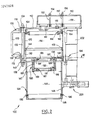
- the front end of the brushing device is shown at the bottom of FIG. 1.
- the end of this device most distant from the joint plane will be called the “rear end” of the brushing device.
- the rear end is shown at the top of Figure 1.
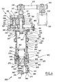
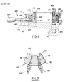
- the brushing device comprises a housing 100 shown in FIG. 2, means 200 for driving the brush in rotation represented in FIG. 3, means 300 for driving in rotation of the rotary assembly around the main axis AA shown in FIG. 4 and means 400 shown in FIGS. 5 and 6 adapted to fix the housing of the brushing device on a tank.
- the housing 100 includes a rear flange 110, a rear skirt 120, an intermediate flange 130 and a front skirt 140.
- the rear skirt 120 and the front skirt 140 formed from generally cylindrical sleeves are concentric with the main axis A-A.
- the rear flange 110 closes the skirt 120 at its rear end.
- the intermediate flange 130 is interposed between the rear skirt 120 and the front skirt 140.
- a casing 150 is carried by the rear surface of the flange 110. Studs 152 are screwed into the flange 110 and project therefrom towards the rear of the device. The housing 150 is immobilized on the flange 110 with the aid of nuts 154 engaged on the studs 152.
- the housing 150 defines, in combination with the flange 110, a chamber 156 housing pinions 204, 208 and a toothed belt 212 ensuring the drive of the brush 201.
- the rear flange 110 is provided with a through bore which houses a spherical bearing 112 coaxial with the main axis A-A.
- the flange 110 defines, in combination with the rear skirt 120 and the intermediate flange 130, a chamber 114 intended to receive an epicyclic train 330 ensuring the drive of the rotary assembly around the main axis AA.
- a removable plug 116 carried by the flange 110 makes it possible to control the lubrication of the mobile means housed in the chamber 114.
- a toothed crown 160 cooperating with the above-mentioned planetary gear 330 is interposed by its periphery between the rear flange 110 and the rear skirt 120.
- the toothed crown 160 has an internal toothing 162 centered on the main axis A-A.
- pins 164 extending parallel to the main axis AA are engaged in the rear flange 110 and in the ring gear 160.
- a handle 170 is fixed laterally on the housing.
- the handle 170 is fixed by means of screws 172, 174, respectively to the rear flange 110 and to the intermediate flange 130.
- the rear flange 110, the rear skirt 120, the intermediate flange 130 and the front skirt 140 are immobilized by tie rods 102 and associated nuts 104, 106.
- the tie rods 102 extend parallel to the main axis AA and pass through bores made in flanges 118, 132, 142 produced respectively on the periphery of the rear flange 110, of the intermediate flange 130 and of the front skirt 140.
- the nuts 104 , 106 mentioned above are screwed onto the ends of the tie rods 102 and rest against the flanges 118 and 142.
- the rear flange 110, the rear skirt 120 and the intermediate flange 130 are bonded to each other during assembly, for example using a cyanoacrylate adhesive.
- a concentric bearing 134 of the main axis AA is supported on the internal surface of the rear skirt 120 at the connection zone of the latter with the intermediate flange 130.
- the bearing 134 is immobilized in translation parallel to the axis main AA by being pinched between a rib 122 integral with the internal surface of the rear skirt 120 and the rear radial surface of the flange 130.
- the bearing 134 is intended to rotationally support an intermediate bearing of the rotary assembly.
- the intermediate flange 130 has on the inside a veil 136 in the form of a crown extending transversely to the main axis A-A and concentric with the latter.
- the cylinder body 180 On its surface before the web 136 supports a cylinder body 180. Essentially the cylinder body 180 is formed by a sleeve 182 concentric with the main axis AA, and, on the rear, at the level of the web 136 , of an annular rib 184.
- the sleeve 182 of the jack body carries at its front end a ring 186 extending transversely to the main axis A-A and concentric therewith, forming the bottom of the jack.
- the crown 186 and the sleeve 182 are immobilized on the web 136 using screws 188. These come into engagement with the web 136 and extend parallel to the main axis A-A.
- the rib 184 and the crown 186 are provided on their internal cylindrical surfaces, respectively with rings 185, 187.
- the rings 185, 187 serve as a rotation support bearing for the rotary assembly.
- the sleeve 182 is provided, in its thickness, with two channels extending parallel to the main axis A-A.
- One of these channels referenced 189 is shown in FIG. 2.
- channels are drilled in the sleeve 182 from the rear end thereof.
- the channels such as the channel 189 opens into the cylinder chamber 190 defined by the body 182, by means of bore 191 extending radially with respect to the main axis AA, respectively near the rib 184 and of the crown 186.
- the channels 189 open into blind channels 137, 138 formed in the web 136, parallel to the main axis A-A from the front surface of the web 136.
- the axial channels 137 and 138 open respectively into bores 192, 193 produced in the web 136, in a radial direction opposite the main axis AA from the external surface of the intermediate flange 130
- Supply nozzles 194, 195 are screwed onto the outer periphery of the intermediate flange 130 and communicate respectively with the passages 192, 193.
- the motor housing 202 is fixed to the outside of the housing, and more precisely to the rear flange 110 and the front skirt 140.
- the means 203 for supplying the motor 202 preferably formed by a pneumatic motor.
- the front skirt 140 is provided on its internal surface and at its front end with an annular flange 195.
- the annular flange 195 is fixed to the front skirt with screws 196 transverse to the main axis A-A.
- the flange 195 is provided on its outer surface with generally coplanar projections facing the main axis A-A and covering limited angular sectors distributed equally around the main axis A-A. These projections are intended to cooperate with the fixing means 400 shown in Figures 5 and 6 to immobilize the housing of the brushing device on a tank.
- the front skirt 140 is provided with a lateral opening 144 making it possible to connect the internal chamber 146 of the front skirt to a suction device intended to vacuum the residues of brushing.
- the opening 144 can be closed off by a ferrule 148 placed inside the front skirt 140.
- the brush to be driven is referenced 201.
- This brush comprises an annular support body 211 carrying bristles 212 extending radially opposite the axis of rotation, called secondary axis B-B.
- the output shaft of the pneumatic motor 202, directed towards the rear, and extending parallel to the main axis AA is fixed on a motor pinion 204 with external teeth by means of a key 206.
- a journal 220 is rotatably mounted coaxially with the main axis A-A in the housing.
- the pin 220 is rotated by the spherical bearing 112 housed in the rear flange 110 and by a needle bearing 224 housed in the intermediate bearing 340 which will be described in more detail below.
- the pin 220 carries on its rear end a receiving pinion 208.
- the receiving pinion 208 is immobilized in rotation on the pin 220 by a key 210.
- a sealing ring 209 is interposed between the periphery of a cylindrical portion of the receiving pinion 208 and the rear flange 110.
- a toothed belt 212 rotates the driving pinion 204 and the receiving pinion 208.
- a longitudinally grooved shaft 230 is placed in front of the journal 220, substantially coaxially with the latter and coaxially with the main axis A-A.
- the splined shaft 230 is connected to the journal 220 via a flexible connection 226, such as a coupling with metal bellows.
- Such a coupling with metal bellows is formed by a bellows sleeve 227 fixed on two ends 228, 229.
- the ends 228 and 229 are fixed in rotation respectively on the journal 220 and the splined shaft 230 by means of keys 225 .
- An axis 240 placed in front of the splined shaft 230 is rotated around the main axis AA, on the rotary assembly 300 by means of a pair of bearings 242, 244 separated by a cylindrical spacer 246.
- the axis 240 is immobilized in translation on the rotary assembly 300, on the rear by a rib 247 and on the front by a nut 248 engaged on a threaded portion of the axis with the interposition of a washer 249.
- the axis 240 is provided at its rear end with an internally grooved sleeve 250.
- the sleeve 250 is engaged on the splined shaft 230.
- the sleeve 250 is immobilized in rotation and in translation on the axis 240 by means of a pin 252.
- the connection defined between the splined shaft 230 and the sleeve 250 ensures a connection in rotation between these two elements while allowing a free translation between them parallel to the main axis AA.
- the axis 240 carries at its front end a bevel gear 260.
- the bevel gear 260 is immobilized in translation and in rotation on the axis 240 by means of a pin 262.
- An auxiliary shaft 270 is rotated by the crew 300 around the secondary axis B-B extending perpendicular to the main axis A-A.
- the auxiliary shaft 270 is rotated about the axis B-B by a rigid bearing 272 and a needle bush 274 supported by the crew 300.
- the body 211 of the brush 201 is screwed onto the auxiliary shaft 270 in a direction opposite to the direction of rotation of the shaft 270 around the secondary axis B-B.
- a second bevel gear 276 is fixed to rotation on the auxiliary shaft 270 by means of a key 278.
- the second bevel gear 276 meshes with the aforementioned bevel gear 260.
- the drive of the motor 202 ensures the drive of the drive pinion 204 and from there, by means of the toothed belt 212, the drive in rotation about the main axis AA the receiving pinion 208, the journal 220, the flexible connection 226, the splined shaft 230, the sleeve 250, the axis 240 and the bevel gear 260.
- the drive connection defined between the two bevel gears 260 and 276 drives the auxiliary shaft 270 and therefore the brush 201 around the secondary axis BB.
- these drive means 300 use the aforementioned pneumatic motor 202 as well as the driving pinion 204, the receiving pinion 208 and the toothed belt 212.
- the rotary assembly around the main axis A-A and the rotary brush around the secondary axis B-B are rotated by the same motor means.
- the crew comprises an intermediate bearing 340 rotatably mounted on the bearing 134 carried by the rear skirt 120.
- the intermediate bearing 340 is essentially formed by a crown-shaped veil extending transversely to the main axis AA .
- the intermediate bearing 340 carries the needle bearing 224 supporting the journal 220.
- the intermediate bearing 340 is immobilized in translation parallel to the main axis A-A on the above-mentioned bearing 134.
- the rotary assembly around the main axis A-A comprises in front of the intermediate bearing 340, and from the rear towards the front a hollow axis 350 and a housing 360.
- the housing 360 is itself formed by the assembly of different elements. More specifically, the housing 360 comprises from the rear towards the front, generally concentric around the main axis A-A, a centering ring 362, an intermediate part 366, a support part 370 and a casing 380.
- the centering ring 362, the intermediate part 366, the support part 370 and the casing 380 are assembled using screws 372 extending parallel to the main axis A-A.
- the centering ring supports at its rear end a guide ring 363 provided with an annular seal 364 which rests against the cylindrical outer periphery of the hollow axis 350.
- the front end of the hollow axis 350 is provided on its outer periphery with longitudinal grooves parallel to the main axis A-A as illustrated diagrammatically at 352.
- the intermediate piece 366 is provided with a plurality of teeth 368 projecting from its internal surface and meshing with the grooves 352.
- the meshing of the teeth 368 and the grooves 352 ensures a rotational connection between the hollow axis 350 and the housing 360 while allowing relative translation between these elements parallel to the main axis AA.
- the support part 370 is provided with an internal cylinder 372 which supports the bearings 242, 244 and the cylindrical spacer 246.
- the housing 380 defines a chamber 382 which houses the front end of the axis 240, the bevel gear 260, the shaft 270 and the second bevel gear 276.
- the casing 280 also carries on the interior of the housing 282 the needle sleeve 274 and the bearing 272. More specifically, the bearing 272 is carried by a bearing 384 coaxial with the secondary axis BB fixed on the casing 380 opposite of the brush 201. The bearing 272 is immobilized on the bearing 384 with the aid of a cover 386 which moreover closes the casing 380.
- the cover 386 and the bearing 384 are immobilized on the casing 380 using screws 388.
- the housing 380 supports on the side of the brush 201 a sealing ring 390 resting against the periphery of the shaft 270 brush support.
- the cover 386 supports a sealing ring 391 resting on the periphery of the support shaft 270.
- a removable plug 392 carried by the casing 380 makes it possible to control the lubrication of the shaft 270 in the casing 380.
- the latter has substantially at mid-length a rib 352 projecting from its internal surface.
- a helical spring 354 is interposed between the rib 352 and the rear transverse surface of the sleeve 372 secured to the support part 370.
- washers 353 and 373 are interposed between the rear and front ends of the spring 354 and respectively the rib 352 and the sleeve 372.
- the spring 354 biases the housing 360 forwards with respect to the hollow axis 350.
- the forward movement of the housing 360 relative to the hollow axis 350 is limited by a thrust washer 356 fixed to the front transverse surface of the hollow axis 350 by means of screws 358.
- the washer abutment 356 serves as a forward abutment for the serrations 368 provided on the intermediate piece 366.
- the hollow axis 350 is provided on its outer periphery and between the two rings 185, 187 mentioned above with an annular part 351 forming a piston intended to be housed in the chamber 190 defined by the jack body 180.
- the thickness radial of the piston 351, considered opposite the main axis AA corresponds substantially to the radial depth of the chamber 190, opposite the same axis.
- the piston 351 is provided on its outer periphery with a sealing ring 355 resting against the internal periphery of the sleeve 182.
- the piston 351 is immobilized in translation, parallel to the main axis A-A on the hollow axis 350 using two rings 359.
- the hollow axis 350 is linked to rotation with the intermediate bearing 340 but capable of translation relative to the latter parallel to the main axis AA.
- the rear end of the hollow axis 350 is provided with grooves 357 on its outer surface.
- a dog clutch 342 is fixed to the front surface of the intermediate bearing and cooperates with the serrations 357.
- the dog 342 comprises a plate 344 transverse to the main axis A-A and fixed to the intermediate bearing 340 by screws 346, and a sleeve 348 comprising on its internal surface grooves 349 which mesh with the serrations 357.
- the hollow axis and therefore the housing 360 are linked in rotation with the intermediate bearing 340.
- the hollow axis 350 can slide parallel to the main axis A-A relative to the intermediate bearing 340.
- the displacement of the hollow axis parallel to the main axis AA is controlled by selectively directing a fluid under pressure towards one or the other of the nozzles 194, 195, that is to say alternately on one side or on the other side of piston 351.
- a ring gear 332 with internal toothing centered on the main axis A-A is fixed to the rear surface of the intermediate bearing 340 by means of screws 333.
- the journal 220 also carries, substantially at mid-length, a pair of bearings 302, 304 separated by a cylindrical spacer 306.
- a planetary support piece 334 is mounted for rotation about the main axis AA on the journal 220 by means of the bearings 302, 304.
- the support piece 334 is provided with a through bore 336 of axis C-C parallel to the main axis A-A and eccentric with respect thereto.
- a shaft 337 is rotatably mounted in the bore 336 around the axis C-C.
- the shaft 337 is guided in rotation about the axis C-C by needle bearings 338, 339.
- a pinion 320 with external teeth is linked in rotation with the front end of the shaft 337 by means of a key 321.
- the pinion 320 meshes with the ring gear 332.
- Another pinion 322 with external teeth is fixed on the rear end of the shaft 337.
- This pinion 322 meshes itself with an external toothed pinion 324 fixed to the pin 220, between the bearing 302 and the bearing 112, using a key 326.
- the drive of the pneumatic motor 202 ensures the drive of the drive pinion 204 and by means of the toothed belt 212 the rotation drive of the receiving pinion 208, the journal 220 and the pinion 324 around the main axis AA.
- the pinion 324 drives the driven sun gear 322 on the crown 160, the shaft 337 and the sun gear driving 320 in rotation about the axis CC.
- the planetary leading 320 in turn drives in rotation, with speed reduction, the ring gear 332 and from there the intermediate bearing 340, the dog clutch 342, the hollow axis 350 and the housing 360.
- the fixing means 400 shown in FIGS. 5 and 6 comprise a centering flange 410.
- the centering flange 410 has an internal bore 412 allowing the brush 201 to access the joint plane to be brushed.
- the centering flange 410 rests in use, by its front surface 414 against the tank, on the outer periphery of the joint plane to be brushed.
- the centering flange 410 is fixed to tanks by means of a plurality of studs 420 and tightening nuts 422.
- the rods of the studs 420 pass through bores 416 made in the flange 410.
- the bores 416 are equally distributed around the bore 412.
- the bores 416 extend parallel to the axis A-A.
- the above-mentioned bores 416 are produced in a tubular part 418 of the centering flange 410, coaxial with the orifice of the tank and projecting towards the back.
- An auxiliary flange 430 is carried by the rear surface of the tubular part 418.
- the auxiliary flange is fixed to the rear surface of this tubular part 418 by screws 432.
- the auxiliary flange 430 projects radially outward facing the axis of the orifice of the tank with respect to the tubular part 418.
- the auxiliary flange 430 is provided on its rear surface with an annular groove which houses a seal 434 against which rests in use the front transverse surface of the flange 195 secured to the front skirt 140.
- the auxiliary flange 430 supports a cylindrical rod 436 extending parallel to the axis of the orifice of the tank and projecting from the rear surface of the auxiliary flange 430.
- the cylindrical rod 436 serves as polarization.
- a flange 440 is rotatably carried between the rear surface of the centering flange 410 and the front surface of the auxiliary flange 430.
- the collar 440 is provided with a generally cylindrical barrel 442, directed towards the rear, and surrounding the auxiliary flange 430.
- the cylindrical barrel 442 is provided at its rear end with a plurality of projections 444 directed inwards, that is to say towards the axis of the orifice of the tank.
- the projections 444 each cover a limited angular sector complementary to that defined by the projections provided on the outer periphery of the flange 195 secured to the front skirt 180.
- the projections 444 are evenly distributed around the axis of the orifice of the tank.
- the projections 444 provided on the flange 440 are provided, on their front surface, and in position adjacent to their engagement edges, with a surface inclined towards the rear in approach to the engagement edge on the integral projections. of the flange 195, to facilitate the engagement of the projections 444 on those integral with the flange 195.
- the rotation drive of the flange 440 around the axis of the orifice is provided by a lever 450.
- the latter extends substantially radially opposite the axis of the bore 412.
- the lever 450 is mounted for rotation on the flange 440 by means of a pin 452 whose axis extends parallel to the support surface 414 of the centering flange 410 and perpendicular to a radius passing through the axis of the orifice of the tank.
- the latter has an eccentric part 419 which carries a cam 460.
- the cam 460 is fixed to the centering flange 410 by means of screws 462.
- the cam 460 defines a stop surface 464 extending substantially perpendicular to the bearing surface 414 and radially relative to the axis of the orifice of the tank.
- the cam 460 further defines a rear ramp 466, starting from the stopping surface 464 and inclined forwards away from the stopping surface 464, that is to say converging towards the bearing surface 414 of the centering flange away from the stop surface 464.
- the centering flange 410, the auxiliary flange 430 and the flange 440 carried in rotation by these elements are fixed to the tank C by means of studs 420 and tightening bolts 422.
- the lever 450 is then pivoted around the axis of the journal 452 against the spring 454 so that the lever 450 escapes the stop surface 464.
- the lever 450 and the flange 440 are then rotated about the axis of the orifice of the tank over an angular amplitude ⁇ equal to the angular opening of the projections 444 provided on the flange 440.
- the lever 450 then occupies the position shown in broken lines broken in Figure 5. In this position of the projections provided on the front face of the flange 440 come to bear against spacers 411, forming a stop fixed on the rear face of the flange 410 by screws 413. These spacers 411 therefore define an indexing of the collar 440.
- the brushing device proper comprising in combination the elements shown in FIGS. 2, 3 and 4 is then positioned on the fixing means 400.
- the projections provided on the outer periphery of the flange 195 are interposed between the projections 444 secured to the flange 440, the front surface of the flange 195 coming to rest against the annular seal 434.
- the main axis A-A of the brushing device is then coaxial with the orifice of the tank.
- the lever 450 is pivoted around the axis A-A back to its original position.
- the lever 450 slides on the ramp 466 and comes to rest against the stop surface 464.
- the spring 454 maintains the lever 450 in this position.
- the flange 440 cannot pivot towards the release position of the brushing device corresponding to the position shown in broken dashed lines for the lever 450 in FIG. 5.
- the projections provided on the outer periphery of the flange 195 are then pinched between the rear surface of the auxiliary flange 430 and the front surface of the projections 444.
- the brushing device is thus held firmly in position, the main axis A-A being coaxial with the axis of the orifice of the tank.
- the brushing device is ready for operation.
- the housing 360 and the brush 201 carried by the latter are retracted backwards.
- the piston 351 is placed in position adjacent to the rib 184 in the cylinder chamber 190.
- the motor 202 is powered.
- the rotational drive of the motor 202 ensures, on the one hand, the rotation of the hollow axis 350 and of the housing 360 around the main axis AA via the planetary gear 330, on the other hand, the rotary drive of the brush 201 around the secondary axis BB via the journal 220, the splined shaft 230, the sleeve 250, the axis 240 and the bevel gear 260, 276.
- the brush 201 thus scans a brush-shaped brushing surface centered on the main axis A-A and the radius of which is defined by the distance separating the brush 201 from the main axis A-A.
- a pressurized fluid is injected, via one of the nozzles 194, 195 on the rear of the piston 351, into the chamber 190 to move the hollow axis 350 forwards, approaching the joint plane to brush.
- the sleeve 250, the axis 240, the pinions 260 and 276, the shaft 270 and the brush 201, are also moved forward because of the translational connection defined between the axis 240 and the bearings 242, 244 .
- the brush 201 then comes to rest against the joint plane to be brushed.
- the force exerted by the brush on the joint plane is defined by the setting force of the spring 354 interposed between the hollow axis 350 and the housing 360.
- a pressurized fluid is applied via the other nozzle, 195 or 194 to the front of the piston 351 to move the piston, as well as the hollow axis 350 and the housing 360, by means of the stop 356, towards the rear, that is to say away from the joint plane to be brushed.
- the motor 202 is then stopped.
- centering flange 410, the auxiliary flange 430 and the flange 440 are removed by loosening the bolts 422.
- the studs 420 are also removed.
- suction means connected to the orifice 144 provided in the front skirt 140 can make it possible to remove the brushing residues.
Landscapes
- Cleaning In General (AREA)
Applications Claiming Priority (2)
| Application Number | Priority Date | Filing Date | Title |
|---|---|---|---|
| FR8607235 | 1986-05-21 | ||
| FR8607235A FR2598944B1 (fr) | 1986-05-21 | 1986-05-21 | Dispositif de brossage du plan de joint d'orifices d'acces pour cuves |
Publications (1)
| Publication Number | Publication Date |
|---|---|
| EP0247928A1 true EP0247928A1 (de) | 1987-12-02 |
Family
ID=9335445
Family Applications (1)
| Application Number | Title | Priority Date | Filing Date |
|---|---|---|---|
| EP87401145A Withdrawn EP0247928A1 (de) | 1986-05-21 | 1987-05-21 | Vorrichtung zum Bürsten der Verbindungsflächen der Zugangsöffnungen von Kesseln |
Country Status (2)
| Country | Link |
|---|---|
| EP (1) | EP0247928A1 (de) |
| FR (1) | FR2598944B1 (de) |
Cited By (5)
| Publication number | Priority date | Publication date | Assignee | Title |
|---|---|---|---|---|
| FR2630506A1 (fr) * | 1988-04-21 | 1989-10-27 | Creation Mecanismes Autom Asse | Dispositif d'ancrage dans un alesage taraude et machine de brossage incorporant un tel dispositif |
| WO1990014212A1 (en) * | 1989-05-15 | 1990-11-29 | E.I. Du Pont De Nemours And Company | Apparatus for removing fouling deposits from dielectric surface of electrostatic charge target electrode |
| DE9413201U1 (de) * | 1994-08-16 | 1996-01-04 | Siemens AG, 80333 München | Vorrichtung zum Reinigen einer Dichtfläche |
| CN114273350A (zh) * | 2021-12-07 | 2022-04-05 | 浙江天工液压机械股份有限公司 | 一种油缸生产用清洗设备 |
| CN120325589A (zh) * | 2025-06-16 | 2025-07-18 | 内蒙古龙马铸造有限公司 | 一种大型风电核心球墨铸铁零部件机加孔内腔清理装置 |
Families Citing this family (1)
| Publication number | Priority date | Publication date | Assignee | Title |
|---|---|---|---|---|
| FR2631256B1 (fr) * | 1988-05-10 | 1990-08-31 | Electricite De France | Dispositif de brossage du plan de joint d'un trou d'homme prevu pour l'acces a l'interieur d'une cuve |
Citations (3)
| Publication number | Priority date | Publication date | Assignee | Title |
|---|---|---|---|---|
| FR631992A (fr) * | 1927-04-02 | 1927-12-29 | Appareil à polir, cirer, brosser le parquet, etc. | |
| US3922748A (en) * | 1974-05-09 | 1975-12-02 | Us Energy | Reactor vessel seal service fixture |
| FR2512358A1 (fr) * | 1981-09-08 | 1983-03-11 | Voigt Lothar | Appareil a nettoyer la surface d'etancheite du bord d'un trou-d'homme |
-
1986
- 1986-05-21 FR FR8607235A patent/FR2598944B1/fr not_active Expired
-
1987
- 1987-05-21 EP EP87401145A patent/EP0247928A1/de not_active Withdrawn
Patent Citations (3)
| Publication number | Priority date | Publication date | Assignee | Title |
|---|---|---|---|---|
| FR631992A (fr) * | 1927-04-02 | 1927-12-29 | Appareil à polir, cirer, brosser le parquet, etc. | |
| US3922748A (en) * | 1974-05-09 | 1975-12-02 | Us Energy | Reactor vessel seal service fixture |
| FR2512358A1 (fr) * | 1981-09-08 | 1983-03-11 | Voigt Lothar | Appareil a nettoyer la surface d'etancheite du bord d'un trou-d'homme |
Cited By (7)
| Publication number | Priority date | Publication date | Assignee | Title |
|---|---|---|---|---|
| FR2630506A1 (fr) * | 1988-04-21 | 1989-10-27 | Creation Mecanismes Autom Asse | Dispositif d'ancrage dans un alesage taraude et machine de brossage incorporant un tel dispositif |
| WO1989010490A1 (fr) * | 1988-04-21 | 1989-11-02 | Creation De Mecanismes D'automatismes Et D'asservi | Dispositif d'ancrage dans un alesage taraude et machine de brossage incorporant un tel dispositif |
| EP0342081A1 (de) * | 1988-04-21 | 1989-11-15 | Creation De Mecanismes D'automatismes Et D'asservissements | Vorrichtung zur Verankerung in einer Gewindebohrung und mit einer derartigen Vorrichtung versehenen Bürstenmaschine |
| WO1990014212A1 (en) * | 1989-05-15 | 1990-11-29 | E.I. Du Pont De Nemours And Company | Apparatus for removing fouling deposits from dielectric surface of electrostatic charge target electrode |
| DE9413201U1 (de) * | 1994-08-16 | 1996-01-04 | Siemens AG, 80333 München | Vorrichtung zum Reinigen einer Dichtfläche |
| CN114273350A (zh) * | 2021-12-07 | 2022-04-05 | 浙江天工液压机械股份有限公司 | 一种油缸生产用清洗设备 |
| CN120325589A (zh) * | 2025-06-16 | 2025-07-18 | 内蒙古龙马铸造有限公司 | 一种大型风电核心球墨铸铁零部件机加孔内腔清理装置 |
Also Published As
| Publication number | Publication date |
|---|---|
| FR2598944A1 (fr) | 1987-11-27 |
| FR2598944B1 (fr) | 1988-09-16 |
Similar Documents
| Publication | Publication Date | Title |
|---|---|---|
| FR2508359A1 (fr) | Porte-outil pour perceuses et perceuses a percussion | |
| FR2504867A1 (fr) | Systeme d'entrainement d'un vehicule a quatre roues motrices | |
| FR2485688A1 (fr) | Procede et appareil pour la realisation d'un branchement sur une canalisation | |
| EP0588713B1 (de) | Fräs-, Planfräs- und Polier-Maschine für automatischen Werkzeugwechsel und entsprechende Vorrichtung | |
| FR2525365A1 (fr) | Dispositif de commande a manivelle pour toit ouvrant de vehicule automobile | |
| FR2598944A1 (fr) | Dispositif de brossage du plan de joint d'orifices d'acces pour cuves | |
| CH615824A5 (de) | ||
| WO2022018335A1 (fr) | Boîtier de transmission et engin automoteur roulant équipé d'un boîtier de transmission | |
| EP0788950B1 (de) | Kraftfahrzeug-Scheibenwischervorrichtung mit Scheibenwischer-Indexierungsmittelnunter Berücksichtigung der Antriebswelle | |
| WO2020240120A1 (fr) | Dispositif d'accouplement de deux arbres et dispositif d'attelage muni d'un tel dispositif d'accouplement | |
| EP0416003B1 (de) | Revolver für werkzeugmaschinen | |
| EP0262048B1 (de) | Gerät zum automatischen Läppen von Elektroden von Schweissrobotern | |
| EP0282388A1 (de) | Vorrichtung zum Ausbürsten von Gewindebohrungen | |
| EP0726123A1 (de) | Roboter verbundenes Werkzeug zum Montieren von Dichtungsstreifen | |
| FR2561172A1 (fr) | Dispositif de reglage de coincidence peripherique sur des machines rotatives d'impression | |
| US4887328A (en) | Device for brushing sealing surfaces of enclosure access holes | |
| FR2505235A1 (fr) | Machine a lisser, en particulier pour parquets en bois | |
| EP0506500B1 (de) | Vorrichtung zum Umwandeln einer drehenden Bewegung in eine oszillierende Bewegung | |
| FR2570670A1 (fr) | Dispositif d'entrainement d'un enrouleur de voile | |
| FR2529843A1 (fr) | Dispositif de reglage de l'orientation de deux projecteurs d'un vehicule | |
| FR2543866A1 (fr) | Dispositif de blocage et de deblocage automatiques d'un outil dans une broche rotative de machine-outil | |
| EP0744588B1 (de) | Vorrichtung zur Herstellung einer abnehmbaren Verbindung zwischen einem Verschluss und einer Wiege eines Geschützes | |
| FR2887831A1 (fr) | Mecanisme de conversion d'un mouvement de rotation permettant une reduction d'amplitude angulaire et dispositif d'essuyage incorporant un tel mecanisme | |
| FR2519284A1 (fr) | Telemanipulateur | |
| EP0081160A1 (de) | Verlängerungsvorrichtung für die Vorgelegewelle eines Schaltgetriebes für Kraftfahrzeuge |
Legal Events
| Date | Code | Title | Description |
|---|---|---|---|
| PUAI | Public reference made under article 153(3) epc to a published international application that has entered the european phase |
Free format text: ORIGINAL CODE: 0009012 |
|
| AK | Designated contracting states |
Kind code of ref document: A1 Designated state(s): BE CH DE ES GB IT LI NL SE |
|
| RAP1 | Party data changed (applicant data changed or rights of an application transferred) |
Owner name: CREATION DE MECANISMES D'AUTOMATISMES ET D'ASSERVI |
|
| 17P | Request for examination filed |
Effective date: 19880530 |
|
| 17Q | First examination report despatched |
Effective date: 19890407 |
|
| STAA | Information on the status of an ep patent application or granted ep patent |
Free format text: STATUS: THE APPLICATION IS DEEMED TO BE WITHDRAWN |
|
| 18D | Application deemed to be withdrawn |
Effective date: 19900808 |
|
| RIN1 | Information on inventor provided before grant (corrected) |
Inventor name: HANSER, PATRICK |