EP0247960A1 - Führung für Gardinen - Google Patents
Führung für Gardinen Download PDFInfo
- Publication number
- EP0247960A1 EP0247960A1 EP87500030A EP87500030A EP0247960A1 EP 0247960 A1 EP0247960 A1 EP 0247960A1 EP 87500030 A EP87500030 A EP 87500030A EP 87500030 A EP87500030 A EP 87500030A EP 0247960 A1 EP0247960 A1 EP 0247960A1
- Authority
- EP
- European Patent Office
- Prior art keywords
- rail
- guide
- piece
- curtain
- designed
- Prior art date
- Legal status (The legal status is an assumption and is not a legal conclusion. Google has not performed a legal analysis and makes no representation as to the accuracy of the status listed.)
- Granted
Links
- 230000000284 resting effect Effects 0.000 claims description 6
- 230000008878 coupling Effects 0.000 claims description 5
- 238000010168 coupling process Methods 0.000 claims description 5
- 238000005859 coupling reaction Methods 0.000 claims description 5
- 230000002441 reversible effect Effects 0.000 claims description 5
- 230000005489 elastic deformation Effects 0.000 claims description 4
- 238000010079 rubber tapping Methods 0.000 claims description 3
- 230000005484 gravity Effects 0.000 claims description 2
- 239000000463 material Substances 0.000 claims description 2
- 230000002787 reinforcement Effects 0.000 claims description 2
- MHNSPTUQQIYJOT-CULRIWENSA-N (3z)-3-(6h-benzo[c][1]benzoxepin-11-ylidene)-n,n-dimethylpropan-1-amine;hydrochloride Chemical compound Cl.C1OC2=CC=CC=C2C(=C/CCN(C)C)\C2=CC=CC=C21 MHNSPTUQQIYJOT-CULRIWENSA-N 0.000 claims 1
- 239000000872 buffer Substances 0.000 description 1
- 238000005096 rolling process Methods 0.000 description 1
- 238000007789 sealing Methods 0.000 description 1
- 239000000725 suspension Substances 0.000 description 1
Images






Classifications
-
- A—HUMAN NECESSITIES
- A47—FURNITURE; DOMESTIC ARTICLES OR APPLIANCES; COFFEE MILLS; SPICE MILLS; SUCTION CLEANERS IN GENERAL
- A47H—FURNISHINGS FOR WINDOWS OR DOORS
- A47H5/00—Devices for drawing draperies, curtains, or the like
- A47H5/02—Devices for opening and closing curtains
- A47H5/032—Devices with guiding means and draw cords
-
- A—HUMAN NECESSITIES
- A47—FURNITURE; DOMESTIC ARTICLES OR APPLIANCES; COFFEE MILLS; SPICE MILLS; SUCTION CLEANERS IN GENERAL
- A47H—FURNISHINGS FOR WINDOWS OR DOORS
- A47H15/00—Runners or gliders for supporting curtains on rails or rods
- A47H15/04—Gliders
-
- A—HUMAN NECESSITIES
- A47—FURNITURE; DOMESTIC ARTICLES OR APPLIANCES; COFFEE MILLS; SPICE MILLS; SUCTION CLEANERS IN GENERAL
- A47H—FURNISHINGS FOR WINDOWS OR DOORS
- A47H1/00—Curtain suspension devices
- A47H1/04—Curtain rails
- A47H2001/042—Curtain rails shaped as curtain rods
-
- A—HUMAN NECESSITIES
- A47—FURNITURE; DOMESTIC ARTICLES OR APPLIANCES; COFFEE MILLS; SPICE MILLS; SUCTION CLEANERS IN GENERAL
- A47H—FURNISHINGS FOR WINDOWS OR DOORS
- A47H1/00—Curtain suspension devices
- A47H1/04—Curtain rails
- A47H2001/045—Curtain rails being curved
Definitions
- This invention refers to a guide for sliding curtains and similar, of the type comprising a support rail, with straight and/or curved sections, provided as required with slotted holes for direct attachment to the ceiling, with its side arms bent inwards at the ends.
- the guide also comprises curtain cord guide and/or return terminal pieces at its ends, other intermediate angle connectors between adjacent rail sections, support fixtures for fastening the guide to the wall or ceiling, and stretchers for the afore-mentioned curtain cord.
- curtain guides there are many curtain guides known nowadays, but in all of them, when the curtain has to follow the- recesses and protrusions of the walls in a room, the guide installer is compelled to use an adequate tool to bend the guide on site, adapting it to each variation of shape of the wall (columns, window spaces, blind cases, etc.)
- the guide in question is basically characterised by the fact that the above-mentioned rail is fitted with inner lips designed for contacting at the bottom with the top of corresponding inside shoulders provided on the above-mentioned terminal pieces.
- the rail is also fitted with longitudinal recesses designed to receive their respective close-fitting connectors, consisting of rods provided with a centre slot.
- each terminal piece consists of a framework which comprises a main body with two side sKirts linked by three bridge portions. These have four inner side slots cut in them, facing each other in pairs.
- Curtain cord guide and/or return pulley spindles can engage in these, with a choice of two positions each.
- Each of these spindless is firmly engaged at the bottom of a corresponding pair of slots by the tight fit of its outside edges against the bottom.
- Each spindle end is prevented from coming out of its portion of slot since this narrows near the bottom.
- the main body is provided in one end bridge portion with a self-tapping screw to be applied against the inside face of the top centre arm of the rail.
- Each terminal piece may be fitted with an end cover piece or an intermediate cover piece, for coupling to the respective terminal and for housing at least one curtain hanger.
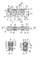
- the guide in question represented diagrammatically in'Figs. 1 and 2 in just one of the ways in which it may be produced, comprises a support rail 1 with either straight sections (Figs. 4 and 6) or curved sections (Fig. 8, 9, 19 and 11), provided as required with slotted holes, with its side sections 3 bent inwards at the ends 4.
- the guide 1 also comprises guide and/or return terminals 7 for the curtain cord 11, other intermediate angle connections 27 between adjacent sections of rail 1, support fixtures 9 for attaching the guide to the wall or ceiling, and stretchers 10 for the curtain cord 11.
- the rail 1 is equipped with inner lips 12 designed for contacting at the bottom with the top of corresponding inner shoulders 13 provided on the respective terminals 7.
- the rail 1 is also provided with longitudinal recesses 14 designed to receive respective close-fitting couplings 15, consisting of rods with a centre slot 16.
- Each terminal 7 is made up of a framework which consists of a main body with two side sKirts 17 linKed by three bridge portions 18, 19 and 20. Cut in each of these are four inner side slots 22, opposite each other in pairs, in which the respective spindles of the curtain cord guide and/or return pulleys can engage, with a choice of two positions each. Each of these spindles is engaged firmly at the bottom of a corresponding pair of slots through the tight fit of its edges against the bottom. Each spindle end is prevented from coming out of its portion of slot through a constriction 24 in it near the bottom.
- the main body is provided with a self-tapping screw 25 for tightening against the inside face of the top middle arm of the rail 1.
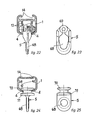
- Each terminal 7 may be fitted with an end cover piece (Figs. 16, 17 and 18) or an intermediate cover piece 27 (Figs. 20 and 21) for coupling to the respective terminal 7 and for housing at least one curtain hanger 5.
- cover piece 26 and 27 comprises a first hollow outer portion 28 designed for its attachment 5 to the wall or to the ceiling by means of the holes 29 and 30 drilled in it.
- Each cover piece 26 or 27 comprises a second middle portion 31 with inner shoulder 32 designed for resting against the inner flanges of the rail 1 and with a bottom recess 33 for housing the head of a curtain hanger 5.
- It also has a third inner portion 34 consisting of a blocK designed so that a vertical screw 25 may be threaded in for tightening against the inside face of the top arm of rail 1 for attachment purposes.
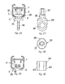
- the guide comprises at least one stop and hanger piece 35 (Figs. 26, 27 and 28), consisting of a lower portion with a hanger ring 36 and an upper portion which is made up of a vertical stem 37 and a rectangular-shaped plate 38 perpendicular to the stem 37.
- This plate is slightly domed underneath and it has a width somewhat less than that of the bottom longitudinal opening 40 in the rail and a length somewhat less than that of the inside width of the rail 1.
- the guide also comprises at least one locking piece 39 for the opening 40 in the rail 1, which has a basically flattened rectangular configuration with an inverted U cross section.
- the side arms 42 of the piece 39 have lengthwise grooves 43 designed to receive the respective free edges of the arms 3 of the rail 1.
- This locking piece 39 is composed of a resilient flexible material which allows it to be pressed up into the. opening 40 in the rail 1 through elastic deformation of the piece. It is also removed through elastic deformation by pressing the side arms 42 of this piece 39 towards each other until the ends 4 of the side arms 3 of the rail 1 are freed from the side grooves 43 in the piece 39.
- the crossover and overlap device 6 comprises one or two supplementary curtain support slides 44. Each of these has a pair of slip elements 45 located on top of the ends of the slide 44 and provided with a flat, smooth, horizontal top surface 46 designed to support the curtain cords 11.
- Each of these slip elements 45 has a transverse rear sharp edge 48 designed to help guide the cords 11 on their -way down to the body of the slide 44.
- This body consists of a horizontal U-section plate placed vertically and provided with a centre hole 50, two notches 51 in the bottom edge and a lower transverse flange 52 with an inverted T cross section. All this is to allow the cord 11 to be wound through the hole 50 and the notches 51 so that the slide 44 is attached firmly to the cord 11.
- each slide 44 has a hole 47 below each slip element 45 either to receive a hanger of the moving end or ends of the curtain or suitable fastenings for a reversible crossover or overlap plate 53.
- This also has holes 54 for receiving curtain hangers 5 or else an operating rod 55 (Fig. 2).
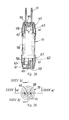
- the stretchers 10 comprises at least one gravity tensioning device for cords 11 which consists of (Figs. 35 and 36) a centre weight body 56 with heads 57 firmly attached at either end that also hang from the cord loop 11.
- Each head 57 comprises a hollow outer cap 58 with an inlet 59 in its end base for the cord 11 in approximately semicircumferential arc. It also has an L-section inner middle portion 60 with a half-doughnut-shaped notch 61 where cord 11 slides and an inward-facing lip 62 designed to prevent fortuitous movement of the cord 11.
- reinforcement ribs 63 which also act as buffers for the centre load body 56.
- Each fixture 9 for supporting or attaching the guide to the wall or ceiling comprises a lockplate 64 for fastening to the horizontal arm of an angle bracket (Figs. 37 and 38) or directly to the ceiling (Fig. 39).
- the locKplate 64 is fitted with a swivel plate 65 with bottom fins 66 for fitting into side grooves 14 CFig. 3) of a lengthwise inverted T-section channel in the rail 1.
- This swivel plate 65 has a curved operating rod 67.
- a shim 41 designed to be applied over piece 26 or piece 27 (Figs. 16 and 20) in order to compensate for the diference in height of the rail 1, in the event of it not being attached directly to the ceiling.
- Figs. 22 to 25 Two ways of producing a hanger 5 are illustrated in Figs. 22 to 25. In both cases they comprise a bottom part with a hole 68 and, in the case of Figs. 22 and 23, rolling members 69, whilst in the case of Figs. 24 and 25 they include sliding members 70 and a flange 71 to stop them getting inside the rail 1.
Landscapes
- Curtains And Furnishings For Windows Or Doors (AREA)
- Paper (AREA)
- Eye Examination Apparatus (AREA)
- Pinball Game Machines (AREA)
- Polymerisation Methods In General (AREA)
- Forklifts And Lifting Vehicles (AREA)
- Toys (AREA)
- Holders For Apparel And Elements Relating To Apparel (AREA)
Priority Applications (1)
| Application Number | Priority Date | Filing Date | Title |
|---|---|---|---|
| AT87500030T ATE58826T1 (de) | 1986-05-27 | 1987-05-27 | Fuehrung fuer gardinen. |
Applications Claiming Priority (2)
| Application Number | Priority Date | Filing Date | Title |
|---|---|---|---|
| ES294655 | 1986-05-27 | ||
| ES1986294655U ES294655Y (es) | 1986-05-27 | 1986-05-27 | Guia para cortinas correderas y analogos |
Publications (2)
| Publication Number | Publication Date |
|---|---|
| EP0247960A1 true EP0247960A1 (de) | 1987-12-02 |
| EP0247960B1 EP0247960B1 (de) | 1990-12-05 |
Family
ID=8441489
Family Applications (1)
| Application Number | Title | Priority Date | Filing Date |
|---|---|---|---|
| EP87500030A Expired - Lifetime EP0247960B1 (de) | 1986-05-27 | 1987-05-27 | Führung für Gardinen |
Country Status (5)
| Country | Link |
|---|---|
| EP (1) | EP0247960B1 (de) |
| AT (1) | ATE58826T1 (de) |
| DE (1) | DE3766540D1 (de) |
| ES (1) | ES294655Y (de) |
| GR (1) | GR3001428T3 (de) |
Families Citing this family (1)
| Publication number | Priority date | Publication date | Assignee | Title |
|---|---|---|---|---|
| ES2270679B1 (es) * | 2004-12-21 | 2008-02-16 | Sistemas Delfin, S.L. | Guia multiple deslizante para cortinas. |
Citations (5)
| Publication number | Priority date | Publication date | Assignee | Title |
|---|---|---|---|---|
| US3248749A (en) * | 1964-06-29 | 1966-05-03 | Ivor V Williams | Hanging drapery support |
| FR1601619A (de) * | 1968-01-05 | 1970-09-07 | ||
| DE2445621A1 (de) * | 1974-09-25 | 1976-04-15 | Rigola Werk Schmidt Julius | Vorhangzugvorrichtung |
| GB2115687A (en) * | 1982-02-23 | 1983-09-14 | Konrad Bratschi | Curtain suspension systems |
| EP0122358A2 (de) * | 1983-04-07 | 1984-10-24 | ARQUATI S.p.A. | Aufhängevorrichtung für einen Vorhang mit Zugorgan mittels einer hohlen Trageschiene |
-
1986
- 1986-05-27 ES ES1986294655U patent/ES294655Y/es not_active Expired - Lifetime
-
1987
- 1987-05-27 EP EP87500030A patent/EP0247960B1/de not_active Expired - Lifetime
- 1987-05-27 DE DE8787500030T patent/DE3766540D1/de not_active Expired - Lifetime
- 1987-05-27 AT AT87500030T patent/ATE58826T1/de not_active IP Right Cessation
-
1991
- 1991-02-01 GR GR91400139T patent/GR3001428T3/el unknown
Patent Citations (5)
| Publication number | Priority date | Publication date | Assignee | Title |
|---|---|---|---|---|
| US3248749A (en) * | 1964-06-29 | 1966-05-03 | Ivor V Williams | Hanging drapery support |
| FR1601619A (de) * | 1968-01-05 | 1970-09-07 | ||
| DE2445621A1 (de) * | 1974-09-25 | 1976-04-15 | Rigola Werk Schmidt Julius | Vorhangzugvorrichtung |
| GB2115687A (en) * | 1982-02-23 | 1983-09-14 | Konrad Bratschi | Curtain suspension systems |
| EP0122358A2 (de) * | 1983-04-07 | 1984-10-24 | ARQUATI S.p.A. | Aufhängevorrichtung für einen Vorhang mit Zugorgan mittels einer hohlen Trageschiene |
Also Published As
| Publication number | Publication date |
|---|---|
| ES294655U (es) | 1989-08-01 |
| ATE58826T1 (de) | 1990-12-15 |
| GR3001428T3 (en) | 1992-09-25 |
| DE3766540D1 (de) | 1991-01-17 |
| ES294655Y (es) | 1990-03-01 |
| EP0247960B1 (de) | 1990-12-05 |
Similar Documents
| Publication | Publication Date | Title |
|---|---|---|
| US5263594A (en) | Curtain rod for slidably supporting a curtain around an intermediate corner, and intermediate junction element therefor | |
| US4646808A (en) | Cordlock structure for a blind assembly | |
| US5271585A (en) | Modular fiber optics raceway permitting flexible installation | |
| CA2172118C (en) | Runner-trim connector | |
| US20210030188A1 (en) | Hangable Apparatus and Systems and Methods Therefor | |
| US4549375A (en) | Ceiling construction | |
| US6409415B1 (en) | Hanger | |
| US3693696A (en) | Traverse assembly for draperies and the like | |
| US12396586B2 (en) | Hangable apparatus and systems and methods therefor | |
| EP0247960A1 (de) | Führung für Gardinen | |
| US5207025A (en) | Automatic friction shoe | |
| US2747218A (en) | Drapery or curtain mounting | |
| US3698035A (en) | Traverse assembly for draperies and the like | |
| US4513804A (en) | Venetian blind hanger pivot assembly including a hanger pivot member having a slat engaging surface | |
| US4357983A (en) | Encompass drapery support assembly | |
| US4402109A (en) | Traverse rod and pulley housing assembly | |
| GB2142816A (en) | Curtain track assembly | |
| JPS61156533U (de) | ||
| CN219645401U (zh) | 一种便于安装的拉幕蚊帐 | |
| JPH07986Y2 (ja) | ハンガーの構造 | |
| US3419065A (en) | Cafe traverse rod | |
| KR970004538Y1 (ko) | 건물 천정 시공용 받침대 | |
| KR0125975Y1 (ko) | 연결식 칸막이 | |
| EP0122358A2 (de) | Aufhängevorrichtung für einen Vorhang mit Zugorgan mittels einer hohlen Trageschiene | |
| JPH0450750Y2 (de) |
Legal Events
| Date | Code | Title | Description |
|---|---|---|---|
| PUAI | Public reference made under article 153(3) epc to a published international application that has entered the european phase |
Free format text: ORIGINAL CODE: 0009012 |
|
| AK | Designated contracting states |
Kind code of ref document: A1 Designated state(s): AT BE CH DE FR GB GR IT LI LU NL SE |
|
| 17P | Request for examination filed |
Effective date: 19880517 |
|
| 17Q | First examination report despatched |
Effective date: 19890926 |
|
| GRAA | (expected) grant |
Free format text: ORIGINAL CODE: 0009210 |
|
| AK | Designated contracting states |
Kind code of ref document: B1 Designated state(s): AT BE CH DE FR GB GR IT LI LU NL SE |
|
| REF | Corresponds to: |
Ref document number: 58826 Country of ref document: AT Date of ref document: 19901215 Kind code of ref document: T |
|
| REF | Corresponds to: |
Ref document number: 3766540 Country of ref document: DE Date of ref document: 19910117 |
|
| ET | Fr: translation filed | ||
| ITF | It: translation for a ep patent filed | ||
| ITTA | It: last paid annual fee | ||
| PLBE | No opposition filed within time limit |
Free format text: ORIGINAL CODE: 0009261 |
|
| STAA | Information on the status of an ep patent application or granted ep patent |
Free format text: STATUS: NO OPPOSITION FILED WITHIN TIME LIMIT |
|
| 26N | No opposition filed | ||
| REG | Reference to a national code |
Ref country code: GR Ref legal event code: FG4A Free format text: 3001428 |
|
| EPTA | Lu: last paid annual fee | ||
| EAL | Se: european patent in force in sweden |
Ref document number: 87500030.9 |
|
| REG | Reference to a national code |
Ref country code: GB Ref legal event code: IF02 |
|
| PGFP | Annual fee paid to national office [announced via postgrant information from national office to epo] |
Ref country code: GR Payment date: 20060508 Year of fee payment: 20 |
|
| PGFP | Annual fee paid to national office [announced via postgrant information from national office to epo] |
Ref country code: CH Payment date: 20060509 Year of fee payment: 20 |
|
| PGFP | Annual fee paid to national office [announced via postgrant information from national office to epo] |
Ref country code: GB Payment date: 20060510 Year of fee payment: 20 |
|
| PGFP | Annual fee paid to national office [announced via postgrant information from national office to epo] |
Ref country code: FR Payment date: 20060515 Year of fee payment: 20 Ref country code: AT Payment date: 20060515 Year of fee payment: 20 |
|
| PGFP | Annual fee paid to national office [announced via postgrant information from national office to epo] |
Ref country code: SE Payment date: 20060517 Year of fee payment: 20 Ref country code: LU Payment date: 20060517 Year of fee payment: 20 |
|
| PGFP | Annual fee paid to national office [announced via postgrant information from national office to epo] |
Ref country code: BE Payment date: 20060522 Year of fee payment: 20 |
|
| PGFP | Annual fee paid to national office [announced via postgrant information from national office to epo] |
Ref country code: NL Payment date: 20060531 Year of fee payment: 20 Ref country code: IT Payment date: 20060531 Year of fee payment: 20 |
|
| PGFP | Annual fee paid to national office [announced via postgrant information from national office to epo] |
Ref country code: DE Payment date: 20060718 Year of fee payment: 20 |
|
| PG25 | Lapsed in a contracting state [announced via postgrant information from national office to epo] |
Ref country code: NL Free format text: LAPSE BECAUSE OF EXPIRATION OF PROTECTION Effective date: 20070527 |
|
| REG | Reference to a national code |
Ref country code: GB Ref legal event code: PE20 |
|
| REG | Reference to a national code |
Ref country code: CH Ref legal event code: PL |
|
| EUG | Se: european patent has lapsed | ||
| NLV7 | Nl: ceased due to reaching the maximum lifetime of a patent |
Effective date: 20070527 |
|
| PG25 | Lapsed in a contracting state [announced via postgrant information from national office to epo] |
Ref country code: GB Free format text: LAPSE BECAUSE OF EXPIRATION OF PROTECTION Effective date: 20070526 |
|
| BE20 | Be: patent expired |
Owner name: S.A. *KLEIN-IBERICA Effective date: 20070527 |