EP0248190A2 - Verfahren und Gerät zur Erweiterung der Betriebskapazitäten eines Fernsprechvermittlungssystems - Google Patents
Verfahren und Gerät zur Erweiterung der Betriebskapazitäten eines Fernsprechvermittlungssystems Download PDFInfo
- Publication number
- EP0248190A2 EP0248190A2 EP87105839A EP87105839A EP0248190A2 EP 0248190 A2 EP0248190 A2 EP 0248190A2 EP 87105839 A EP87105839 A EP 87105839A EP 87105839 A EP87105839 A EP 87105839A EP 0248190 A2 EP0248190 A2 EP 0248190A2
- Authority
- EP
- European Patent Office
- Prior art keywords
- data message
- node
- subscriber
- message
- information
- Prior art date
- Legal status (The legal status is an assumption and is not a legal conclusion. Google has not performed a legal analysis and makes no representation as to the accuracy of the status listed.)
- Withdrawn
Links
Images


Classifications
-
- H—ELECTRICITY
- H04—ELECTRIC COMMUNICATION TECHNIQUE
- H04Q—SELECTING
- H04Q3/00—Selecting arrangements
- H04Q3/64—Distributing or queueing
- H04Q3/66—Traffic distributors
- H04Q3/665—Circuit arrangements therefor
-
- H—ELECTRICITY
- H04—ELECTRIC COMMUNICATION TECHNIQUE
- H04Q—SELECTING
- H04Q3/00—Selecting arrangements
- H04Q3/42—Circuit arrangements for indirect selecting controlled by common circuits, e.g. register controller, marker
Definitions
- the present invention relates to telecommunications systems and more particularly to a method and apparatus for enhancing the operation of an existing central office in a telephone switching system to provide extended subscriber features.
- a "central office” includes a plurality of switching elements (e.g., a crossbar or step-by-step switch) for connecting an incoming subscriber call from a subscriber line to one of a plurality of outgoing trunks.
- the central office also includes control circuitry (e.g., originating registers and markers) for receiving and processing called digits from the subscriber and in response thereto controlling the switch element to select an appropriate outgoing trunk to complete the subscriber call.
- a method and apparatus for enhancing the operating capabilities of an existing central office in a telephone switching system is described.
- the central office is enhanced through use of at least one register module interposed between the subscriber line and the originating registers (or equivalent structure) of the office.
- the register module Upon seizure of an originating register by the subscriber going off-hook, the register module supplies a dialtone to the subscriber line and receives line information from the central office identifying this line.
- the subscriber line information is then used to address a database in the register module from which the subscriber's telephone or other identification number and (pre-subscribed) long distance carrier are retrieved. This subscriber information is then stored in a memory of the register module having a plurality of address locations.
- the register module intercepts the called digits to determine whether processing of the call requires an extended subscriber feature, e.g., equal access. Received digits are also stored at the address location in the memory where the subscriber information resides. If processing of the call requires an extended subscriber feature, the register module transmits to the originating register a coded signal including the address location in the memo.ry where the digits and the subscriber information reside. The coded signal also includes information used by the crossar office to route the call to a trunk as well as information identifying the particular register module that is processing the signal.
- the existing central office also includes a call processing "trunk" module interposed between the crossbar switch of the office and the plurality of outgoing trunks.
- the trunk module receives the coded signal from the crossbar switch and in response thereto polls the register module to transmit the actual digits and the subscriber information via a high-speed datalink.
- the trunk module then outputs signals on the selected trunk in a format depending on the subscriber's long distance carrier.
- data messages are transmitted between the various system modules (and tasks therein) via a unique messaging structure and routing method.
- each of the above-identified modules is defined as a "node" of a nodal network, with each of the nodes having one or more ports associated therewith for communicating with other nodes of the network.
- Each of the nodes may also have one or more tasks associated therewith.
- a method for routing data between nodes of the network uses a primary routing table at each node of the network for identifying a port of the node from which data messages should be sent to reach each other node of the network via a shortest possible path.
- a secondary routing table may also be generated at each node for determining which port of the network should be used to route the data message to each other node of the network via a next shortest possible path. Information in the data message is then evaluated to control routing of the data message between nodes (i.e., modules) and between tasks within a given node.
- Each data message to be routed preferably includes a class field, for storing information to control routing of the data message, and a destination node field for identifying a destination node where the data message is to be routed.
- message routing between nodes is accomplished by using the information in the class and destination fields to a) identify the port required for most efficient routing if, in fact, a valid route exists, and b) to identify whether the message, requires external routing (i.e., routing to another node) or internal routing to another task at the same node.
- a method for routing data between nodes of the network begins by compiling the primary and secondary routing tables.
- a data message to be routed is then generated at a source node, the data message including information in the class field used to control routing of the data message and information in the destination node field for identifying the destination node where the message is to be routed.
- the information in the class and destination fields is used to identify the port of the node from which the message should be routed to reach the destination node over the shortest possible path.
- the information is also used to identify whether a valid route exists and whether the message is to be routed externally between nodes of the network or internally between tasks of the source node.
- the generated route information is used to effect routing of the -;ssage between the source and destination nodes.
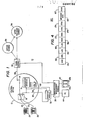
- FIGURE 1 is a simplified block diagram of the apparatus of the present invention for enhancing the operating capabilities of an existing central office in a telephone switching system.
- the switching system 10 includes a conventional central office 12 having at least one crossbar switch element 14, at least one originating register (OR) 16 and a subscriber line link circuit 18.
- First and second subscriber lines 20 and 22 connect first and second subscribers 24 and 26 to the central office equipment.
- the central office 12 also . includes at least one "marker" circuit (not shown), which in conjunction with the originating register 16 controls the crossbar switch element 14 to select one of a plurality of outgoing trunks 28 to complete the subscriber call.
- the originating register 16 receives (from the marker) a parallel input called a line equipment number identification (LENI) code.
- LNI line equipment number identification
- the existing central office 12 of the telephone switching system 10 is enhanced through use of at least one register module 30 interposed between the subscriber lines and the originating register 16.
- the register module 30 operates in conjunction with a trunk module 32 to provide extended subscriber features to the subscribers 24 and 26.
- the operation of the register module 30 and the trunk module 32 will be discussed below in the context of providing subscribers with "equal access” directly to one or more interexchange carriers (IC) 34 (e.g., MCI or GTE SPRINT) or indirectly to such interexchange carriers through an access tandem (AT) 36.
- IC interexchange carriers
- AT access tandem
- This example is not meant to be limiting, as the method and apparatus of the invention is capable of providing many types of extended subscriber features as well as other network services and maintenance capabilities normally associated with central office equipment.
- the central office 12 also includes a communications management module 38 connected between the register module 30 and the trunk module 32 for facilitating intermodule communications and for serving . as a conduit for messaging between the individual modules and external databases (not shown).
- the central office 12 is also modified to include a file management module 40 connected to the communications management module 38.
- File management module 40 preferably includes two file management systems 42a and 42b operating in a redundant configuration. Each file management system includes an appropriate processing unit and hard disk storage for maintaining billing records, operational -easurements and other system files used in the central office 12. All maintenance and administration functions of the enhanced central office 12 are performed through a maintenance console 44 connected to the communications management module 38.
- the maintenance console 44 is a stand-alone personal computer through which system maintenance and administrative personnel maintain and download system databases, view and control operational requirements, invoke maintenance and perform all other operational functions necessary for system administration.
- the enhanced central office will typically include a plurality of register modules 30, a plurality of trunk modules 32, and a plurality of communication management modules 38, Each register module will preferably support up to twenty-four (24) originating registers.
- the trunk modules which provide the primary interface between the crossbar switch and the interexchange carrier 34 or access tandem 36, each include a central processing unit and suitable storage for processing analog signals (e.g., E& M Type I or II signaling) and digital signals (e.g., T1 interface).
- FIGURE 1 discloses the invention in conjunction with a crossbar-type central office
- other types of central offices e.g., a step-by-step office
- the register module 30 is connected in series between the originating register 16 and the link circuit 18 (and the subscriber lines 20 and 22) via the buses 46 and 48.
- the register module 30 is also connected in parallel to the originating register 16 to receive-the LENI codes-via bus 50.
- the strategic position of the register module 30 (or adjacent) within the central office 12 enables the apparatus to intercept signaling information from the subscriber line prior to that information being analyzed by the existing central office equipment. This capability, together with the ability to monitor the LENI information, enables the apparatus to analyze, screen and manipulate the signaling information to thereby offer extended subscriber features as well as other network services and maintenance capabilities to the existing central office.
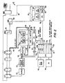
- the central office equipment 12 includes a marker 52 connected to the originating register 16 via a register/marker connector 54.
- the marker 52 determines the terminal locations of calling lines, incoming trunks bidding for service, called lines, and outgoing trunks and equipment, determines the proper route for a call, establishes the connection within the office and passes routing information to the caller, determines the calling line class of service, provides charge classification, and recognizes line busy, trouble, intercept and vacant line conditions.
- Marker 52 also provides the LENI codes to the originating register 16 via the parallel input bus 55.
- Incoming subscriber signals from subscriber 24 are processed through the link circuits MPF, LTF, JTR, TLF and TDF (which correspond to the link circuit 18 in FIGURE 1) and output on the bus 46.
- the register module 30 is connected between the buses 46 and 48 to provide the series connection between the originating register 16 and the subscriber lines.
- the register module includes a central processing unit (CPU) 58 and associated memory 60.
- the LENI code (corresponding to the calling subscriber) is input to a line identification receiver 62 of the register module 30 via the parallel bus 50.
- the line identification receiver 62 provides automatic number identification (ANI) from the LENI code input to identify the calling subscriber's telephone number as well as (pre-subscription) information such as the identity of the subscriber's interexchange carrier. This subscriber information is then stored in the memory 60 at an addressable location and, as will be described, later used by the trunk module 32 to route the subscriber call to the subscriber's interexchange carrier.
- ANI automatic number identification
- the register module 30 includes DP/DTMF send and receive circuits 64 and 66 connected between the buses 46 and 48 for providing time-out signals to the originating register 16 to ensure that signaling information is being properly received by the register module 30.
- the bus 46 on the input side of the register module 30 includes tip and ring lines 68, and a plurality of other leads 70 used to validate the selection of the originating register and to control the timing functions of the register following selection.
- FIGURE 2 also shows how the trunk module 32 is connected to the register module via the communications management module 38.
- communications management module 38 includes a CPU 71 and a plurality of I/O ports 72a-72h, with ports 72a-72e being connected, for example, to other trunk modules or register modules (not shown).
- Port 72f connects to the central processor 58 of the register module 30 via a high speed datalink 74, while the trunk module 32 connects to port 72g via the high speed datalink 76.
- Port 72h connects the communications management module 38 to other similar management modules or external databases (not shown). For example, port 72h can be used to connect the module to a common channel signaling (CCS#7) network to meet future telecommunications requirements.
- CCS#7 common channel signaling
- Trunk module 32 includes a central processing unit 78, associated memory 80 and analog-to-digital (A/D) converter circuits 82. Time-out circuits 84 and 86 are also provided to ensure that the trunk module operates within proper timing constraints.
- the trunk module 32 is connected to an output link circuit 88, which serves to connect the subscriber call via the switch element 14 to the selected trunk 28.
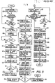
- FIGURE 3 is a flowchart diagram explaining how the modules 30 and 32 provide equal access capability to the otherwise non-conforming central office 12.
- the method begins at step 100 with the register module 30 continually scanning all originating registers (one of which is register 16) for a call origination.
- a test is made to determine if organization signals have been received from the crossbar. If so, a test is made to determine if a subscriber has gone off-hook. If the result of either test at steps 101 or 102 is negative, the method returns to step 100.
- the register module 30 controls the marker 52 to perform all pre-setup tests at step 104.
- step 106 the register module 3 0 intercepts the subscriber's tip and ring signals on conductors 68.
- Step 106 occurs only after the marker 52 determines that a proper originating register 16 has been selected:
- a test is then made to verify that a loop exists between the subscriber line and the register module 30 and that the originating register 16 is supplying a battery feed to its side of the module 30. If all of these conditions exist, the method continues at step 110, where the register module performs a party-coin test.
- the register module attaches a DP/DTMF signal via DP/DTMF send circuit 64 and starts a Permanent Signal (PS) timer therein.
- PS Permanent Signal
- the register module 30 then transmits a dialtone to the calling subscriber at step 114 and performs automatic number identification (ANI) and storage of the subscriber information at step 116.
- ANI automatic number identification
- the LENI code provided by the marker 52 is used by the line identification receiver 62 of the register module 30 as an address to a database which stores the subscriber's telephone number and identification of the subscriber's interexchange carrier. This information is required to provide equal access to the subscriber's interexchange carrier (IC).
- a test is made to determine if a digit has been dialed within a specified time. If not, the register module 30 sends a permanent signal (PS) time-out signal to the originating register 16 at step 120 to cause the register to call for the marker 52 to service the permanent signal. If the test at step 118 indicates that digits are being received, the register module also performs Partial Dial (PD) timing at step 122 until enough digits have been received to process the call to the originating register 16. If a Partial Dial (PD) time-out occurs, the register module sends the digits dialed to the originating register 16 followed by a time-out signal:
- PS permanent signal
- PD Partial Dial
- step 118 There will be some classes of operation, however, where the screening of just one digit (at step 118) will not provide enough information to enable the method to evaluate whether an extended subscriber feature is required. In such cases, the result of step 124 is ambiguous and thus a test is made at step 125 to determine if the second digit (or third digit, and so forth) has been received. If so, the method returns to step 122. However, if the result of step 125 is negative, the method returns to step 120.
- This operation is not meant to be limiting as the method can process one or more received digits to make the extended subscriber feature determination.
- step 126 the register module 30 repeats the dialed digits to the originating register 16.
- the crossbar releases the originating register 16 and the register module 30 prepares for the next call.
- the crossbar also performs call processing to the selected crossbar trunk.
- the crossbar trunk seizes the trunk module at step 128.
- the trunk module 32 signals the selected crossbar trunk and the register module receives the called number.
- the trunk module 32 then sends an off-hook signal to the selected crossbar trunk at step 130.
- step 131 the crossbar sends the calling number over the trunk and the method terminates.
- test 124 determines that processing of the call requires an extended subscriber feature
- the method continues at step 132 to store the called number at the address location in memory where the other subscriber information was stored during step 116.
- the register module generates a pseudocode number which will be used by the marker to route the call to a specific trunk route.
- the pseudocode signal is preferably a seven digit code, NXX-XXXX, with the first three digits thereof ("NXX") assigned by the specific central office to cause routing of the call to one or more trunk routes where trunk - modules 32 are located.
- the last four digits (“XXXX" represent the specific register module 30 at which processing is taking place and the location in memory 60 where the called number and subscriber information resides.
- the method generates a different prefix NXX for the pseudocode signal depending on whether the call will be processed directly to an interexchange carrier or indirectly to a carrier through an access tandem route.
- step 134 the register module 30 transmits the pseudocode signal to the originating register 16.
- step 136 a test is made to determine whether the last digit of the called number has been received. If not, the method continues at step 138 to hold the last digit of the pseudocode in the module 30 or to otherwise prevent the originating register 16 from timing out. If the result of test 136 is positive, the method continues at step 140 to complete the sending of the pseudocode to the crossbar. At step 142, the crossbar releases the originating register 16 and the register module 30 prepares for the next call.
- step 146 the crossbar seizes the appropriate trunk module depending on the value "NXX" of the pseudocode number.
- the crossbar switch sends the pseudocode signal NXX-XXXX to the trunk module 32.
- the trunk module 32 polls the appropriate register module 30 via the communications management module 38 to request transmission of the called number and the other subscriber information stored in memory 60.
- the register module 30 returns this information to the trunk module for subsequent processing.
- the trunk module then analyzes the called number and subscriber information at step 154 to determine whether the call will be routed directly to the interexchange carrier or directly to an access tandem. If the call will be routed directly, the method continues at step 156, where the register module seizes the incoming trunk to the interexchange carrier and processes the call per the appropriate carrier database. If the call is routed through the access tandem, the trunk module 32 seizes the incoming trunk to the tandem and performs appropriate signal processing at step 158.
- the register module receives information (the LENI code) identifying the subscriber line following seizure of the originating register by the subscriber. Dialed digits (or signals representative thereof) are intercepted from the subscriber line and then analyzed to determine whether processing of the subscriber call requires equal access. If so, the register module generates a pseudocode number which includes the address location in the register memory of the stored digits and the subscriber information.
- the trunk module 32 receives the pseudocode number from the crossbar for subsequent processing.
- the pseudocode digits received by the trunk module are not the customer dialed digits but rather identify the register module and the memory location therein which contains the actual dialed number and the subscriber information of the originating subscriber.
- the high speed communications datalink established between the register module and the trunk module (via the communications management module 38) allows the trunk module 32 to poll the register module 30 for the actual dialed digits and the subscriber information.
- the trunk module 32 then outputs the called number and the calling number in a predetermined format (e.g., Feature Group B, C or D format).
- the trunk module 32 also assembles call record data and transmits this data to the file management module 40 of FIGURE 1 for format, storage and later retrieval of billing data.
- data is transmitted between the various system modules (or between tasks therein) via a unique messaging structure and routing method.
- each of the modules discussed above with respect to FIGURES 1 and 2 can be considered nodes of a nodal network through. which data messages are routed.
- this module polls the register module 30 to receive the previously stored called number and the subscriber information.
- Such information is routed through another node of the network, the communications management module 38, having a plurality of ports 72a-72h.
- Such transmission of messages between the various nodes (and tasks thereof) of the network (or between tasks of a single node) is accomplished via the message structure shown in FIGURE 4 and the routing routines set forth in FIGURES 5-10.
- FIGURE 4 discloses a representation of a preferred message structure of the present invention.
- Message 160 includes a message data field 162 which, in the preferred embodiment, may be up to one hundred twenty-two (122) bytes in length.
- the message data field 162 is of sufficient length to normally include all of the information intended to be transmitted between the nodes (or tasks therein).
- the data message 160 also includes a message length byte (LEN) 164 which contains the total number of bytes in the message including the length byte itself.
- the message length is typically one hundred twenty-eight (128) bytes.
- the data message 160 includes a route class byte ( CLA S) 166 which stores information to determine how the message is to be routed through the network.
- a destination node byte (DNOD) 168 identifies a destination node (via a logical identification number) where the data message is to be routed.
- the data message 160 also includes a source node byte (SNOD) 170 which contains the logical identification of the source node itself. This byte is not used to route the message, but is included to serve as a return address if the destination node must respond to the message.
- the data message 160 also includes a destination task byte (DTSK) 172 which contains the identity of the task within the destination node to which the data message is intended.
- DTSK destination task byte
- the data message further includes a source task byte (STSK) 174 which contains the identity of the task in the source node which issued the data message.
- STSK source task byte
- the source task field is not used for message routing, but merely identifies the task address for any return messages.
- Data bytes 162, 164, 166, 168, 170, 172 and 174 form the basic structure of the data message 160 whether messages are to be. routed internally (i.e., between two tasks of the same node), or externally (i.e., between different nodes of the network). However, where the data message 160 is to be routed externally, it is modified at the node to include additional fields by an external messge task (ESTMSG) to be described below.
- data message 160 includes a start-of-message (SOM) byte 178, a frame control (CNTL) byte 180 and a check sum (CKSM) byte 182 for storing information used to control transfer of the message across a datalink between nodes.
- SOM start-of-message
- CNTL frame control
- CKSM check sum
- the CNTL byte 178 supports one of the following types of command or response frames:
- the above command and response frames provide a) link initialization (i.e., the placing of both nodes of the link in a known state), B) error control to ensure that messages reach their destination free of transmission errors and without loss of information, and c) flow control to ensure that the data messages are not sent more rapidly than they can be received.
- EXTMSG external message routing
- the method begins when the task is activated by the node's operating system.
- a data message is dequeued from a task queue in the node.
- the task queue may form a portion of the memory 60 as shown in FIGURE 2.
- the source node byte 170 in the data message is checked to see if this byte is equal to zero. If so, the method continues at step 204 to replace the zero value with the node's own node number. This step relieves the task from the responsibility of filling the source node byte 170 in every message.
- the method continues at step 206 to route the message according to the information in the route class byte 166 and the destination node byte 168.
- a primary routing table is compiled at each node of the network for identifying a port of the node from which a data message should be sent to reach each other node of the network via a shortest possible path.
- a secondary routing table may be compiled at each node for identifying a port of the node from which the data message should be sent to reach each other node of the network via a next shortest, possible path.
- the information in the primary and secondary routing tables is manipulated by the information in the data message control bytes described above to route the data message between the various nodes of the network.
- routing is generally accomplished by using the primary and secondary route tables to find a route for the message while at the same time identifying a port number for use in sending the message to an intermediate node or to the desired destination node (if possible).
- the message route subroutine 206 generates a zero flag (ZF) having a value ZF-"1" if the data message is intended to be routed to a task within the node.
- the flag ZF has a value ZF-"O" if the data message is to be routed externally.
- the carry flag CF is checked to determine whether a route exists for the message. If the carry flag is not equal to "0,” a test is made at step 210 to determine whether the data message is to be routed internally. If so, the data message is sent to the operating system at step 212. If the data message is to be routed externally (to the port number identified by the message route subroutine 206), it is sent to the identified port at step 214. Following step 214, or if the carry flag indicates that no route exists for the data message, the method continues at step 216 to release a message buffer in which the data message was being held by the operating system.
- a test is made to determine whether the information in the route class byte 166 of the data message is equal to zero (the default route class). If the route class byte 166 is equal to zero, the data message is routed directly to its destination node as follows.
- the primary routing table at the node uses the destination node identified in the destination node byte 168 as an index into the table which, as noted above, stores information identifying ports of the node from which data messages should be sent to reach each other node of the network via a shortest possible path.
- a node does not exist in the network, then a value of "-1" is stored in the table at the address. Likewise, the value "-2" is stored at the address if the message is to be routed internally (i.e., between tasks). This would occur, for example, at the address of the node's own node number. Following the destination node-to-port number translation provided at step 220, the method continues at step 222 to determine whether the data message is to be routed internally between tasks of the node.
- step 230 to set the carry flag equal to "1".
- steps 224, 228 or 230 the subroutine returns to step 208 in the routine of FIGURE 5.
- a secondary routing table may be compiled at each node for identifying a port of the node from which the data message should be sent to reach each other node of the network via a next shortest possible path. If the route class byte 166 is non-zero, (i.e., the outcome of the test at step 218 is negative), a test 232 is made to determine whether the information in the route class byte of the data message has a second predetermined value (indicating the need for secondary routine). If the message is to be routed using the secondary route, the destination node is again translated to a port number at step 234 using the secondary routing table. This table contains alternate port numbers from which the message can be sent to its destination node (or an intermediate node) using a next shortest possible path.
- the route class byte 166 may also contain a so-called mate class identification which indicates that the destination node is a redundant ' source node.
- the method includes an additional test at step 242 to determine whether the route class field byte contains the mate class identification. If not, a step 244 is performed to translate the route class byte to the destination node byte via a lookup table. The method then continues at step 220 as described above. If the class field byte contains the mate class identification, then a test is made at step 246 to determine whether the message is destined for the redundant node. If not, the subroutine defaults to step 220.
- the route class byte and port numbers are set to zero at step 248.
- the zero and carry flags are then set to zero and the subroutine returns to step 208 in the routine of FIGURE 5.
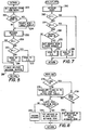
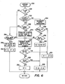
- FIGURE 7 a flowchart diagram is shown of a receive external message (RCV EXT MSG) subroutine which is used by an intermediate node (located between the original source node and the destination node) for use in retransmitting the data message along its journey to the destination node.
- a test is made at step 268 to determine if the source node byte equals zero. If so, at step 270, the subroutine sets the source node equal to the port number identifying the port at which the message was received. Following step 270, or if the result of the test at step 268 is negative, the data message is sent at step 272 to the operating system.
- SEND BUF a preferred routine for routing messages between tasks of a give node
- This internal routing routine begins at step 274 where a test is made to determine whether the class field byte in the data message to be routed is equal to zero. If not, the routine continues at step 276 to translate the class identification byte to the destination node byte 172 via a lookup table. If, however, the class byte is equal to zero, a test is made at step 278 to determine whether the destination node is equal to zero. If not, the message is placed in an external task queue and the task is activated at step 280.
- a test is made at step 282 to determine whether the destination task is valid for the node. If not, the message, is discarded at step 284. However, if the destination task is valid for the node, the message is put in the task queue and the task is activated at step 286.
- a serial communications protocol handler is provided to manage the low-lewel point-to-point data transfer between two nodes.
- messages are received and transmitted on a byte-to-byte basis, and appropriate routines are provided at the transmitting and receiving links (nodes) for forming or reconstructing messages based on the transmitted or received data bytes.
- each data byte is handled on an interrupt basis.
- a receive handler task (FORMMESS) as shown in FIGURE 9 is scheduler for later execution by the operating system.
- the FORMMESS routine takes bytes out of the received byte queue and attempts to form a message from these bytes.
- RCV EXT MSG of FIGURE 7 is called and the message is routed to its destination.
- Data messages to be routed are placed in a transmit message queue by the send to port step 270 of FIGURE 7. Such messages are then made available for transmission by the procedure GETTBYTE of FIGURE 10.
- This procedure which is called during a transmit interrupt, obtains the bytes for. transmission from the transmit message queue.
- the routine GETTBYTE of FIGURE 10 works in conjunction with the routine FORMMESS of FIGURE 9 to provide automatic link-level acknowledgment handshaking to ensure integrity of message transmission and reception.
Landscapes
- Engineering & Computer Science (AREA)
- Computer Networks & Wireless Communication (AREA)
- Exchange Systems With Centralized Control (AREA)
Applications Claiming Priority (2)
| Application Number | Priority Date | Filing Date | Title |
|---|---|---|---|
| US866165 | 1986-05-22 | ||
| US06/866,165 US4782519A (en) | 1986-05-22 | 1986-05-22 | Method and apparatus for enhancing the operating capabilities of a telephone switching system |
Publications (2)
| Publication Number | Publication Date |
|---|---|
| EP0248190A2 true EP0248190A2 (de) | 1987-12-09 |
| EP0248190A3 EP0248190A3 (de) | 1990-07-11 |
Family
ID=25347051
Family Applications (1)
| Application Number | Title | Priority Date | Filing Date |
|---|---|---|---|
| EP87105839A Withdrawn EP0248190A3 (de) | 1986-05-22 | 1987-04-21 | Verfahren und Gerät zur Erweiterung der Betriebskapazitäten eines Fernsprechvermittlungssystems |
Country Status (3)
| Country | Link |
|---|---|
| US (1) | US4782519A (de) |
| EP (1) | EP0248190A3 (de) |
| CA (1) | CA1273090A (de) |
Cited By (6)
| Publication number | Priority date | Publication date | Assignee | Title |
|---|---|---|---|---|
| EP0339127A3 (de) * | 1988-04-27 | 1990-10-24 | Network Access Corporation | Gerät und Verfahren, um eine bestehende Fernsprechschalteinrichtung auszustatten mit der Fähigkeit, das ss7-Protokoll zu benutzen |
| EP0430534A1 (de) * | 1989-11-29 | 1991-06-05 | AT&T Corp. | Steuerung von nicht lokal vermittelten Fernmeldediensten |
| AU618897B2 (en) * | 1989-05-17 | 1992-01-09 | Telstra Corporation Limited | A telecommunications system and routing method |
| WO1996004758A1 (en) * | 1994-08-03 | 1996-02-15 | British Telecommunications Public Limited Company | Telecommunications network |
| ES2105934A1 (es) * | 1994-02-25 | 1997-10-16 | Telefonica Nacional Espana Co | Circuito hibrido universal de linea. |
| EP0898432A1 (de) * | 1997-08-18 | 1999-02-24 | Telefonaktiebolaget Lm Ericsson | Verfahren und System zur Detektion vom Wahlzustand eines kodierten Anrufnummers |
Families Citing this family (59)
| Publication number | Priority date | Publication date | Assignee | Title |
|---|---|---|---|---|
| US5359645A (en) * | 1985-07-10 | 1994-10-25 | First Data Corporation Inc. | Voice-data telephonic interface control system |
| US6678360B1 (en) | 1985-07-10 | 2004-01-13 | Ronald A. Katz Technology Licensing, L.P. | Telephonic-interface statistical analysis system |
| US20020196915A1 (en) * | 1985-07-10 | 2002-12-26 | Katz Ronald A. | Telephone interface call processing system with call selectivity |
| US5828734A (en) | 1985-07-10 | 1998-10-27 | Ronald A. Katz Technology Licensing, Lp | Telephone interface call processing system with call selectivity |
| US5793846A (en) | 1985-07-10 | 1998-08-11 | Ronald A. Katz Technology Licensing, Lp | Telephonic-interface game control system |
| US4845739A (en) | 1985-07-10 | 1989-07-04 | Fdr Interactive Technologies | Telephonic-interface statistical analysis system |
| US5086456A (en) * | 1989-04-24 | 1992-02-04 | Anritsu Corporation | Dial unit detachably mounted on public telephone for equal access |
| US5068891A (en) * | 1989-05-31 | 1991-11-26 | Marshall Marvin E | Credit control system for long distance telephone services |
| US5086461A (en) * | 1990-01-23 | 1992-02-04 | Network Access Corporation | Apparatus and method for providing existing 1ESS and 1AESS telephone switching equipment with the capability of using the SS7 protocol |
| US5241588A (en) * | 1990-12-18 | 1993-08-31 | Bell Communications Research, Inc. | Systems and processes providing programmable or customized customer telephone information services |
| US5825865A (en) * | 1991-10-04 | 1998-10-20 | Motorola, Inc. | Temporary message routing and destination selection |
| US5311584A (en) * | 1991-10-31 | 1994-05-10 | At&T Bell Laboratories | Telecommunications call-processing arrangement |
| US5343517A (en) * | 1991-10-31 | 1994-08-30 | At&T Bell Laboratories | Use-code based call-treatment selection |
| US5333188A (en) * | 1991-10-31 | 1994-07-26 | At&T Bell Laboratories | Dialed number recognition arrangement |
| US5367566A (en) * | 1991-12-27 | 1994-11-22 | At&T Corp. | Common channel signaling message intercept system |
| US5734709A (en) * | 1992-01-27 | 1998-03-31 | Sprint Communications Co. L.P. | System for customer configuration of call routing in a telecommunications network |
| US5812654A (en) * | 1992-01-27 | 1998-09-22 | Sprint Communications Co. L.P. | Telecommunications network routing |
| US5299261A (en) * | 1992-02-24 | 1994-03-29 | At&T Bell Laboratories | Arrangement for effecting segmentation of a dialed number |
| US5511116A (en) * | 1992-08-25 | 1996-04-23 | Bell Communications Research Inc. | Method of creating and accessing value tables in a telecommunication service creation and execution environment |
| US5455853A (en) * | 1992-08-25 | 1995-10-03 | Bell Communications Research, Inc. | Method of creating a telecommunication service template |
| WO1994005112A1 (en) * | 1992-08-25 | 1994-03-03 | Bell Communications Research, Inc. | System and method for creating, transferring, and monitoring services in a telecommunication system |
| US5442690A (en) * | 1992-08-25 | 1995-08-15 | Bell Communications Research, Inc. | Telecommunication service record structure and method of execution |
| US5450480A (en) * | 1992-08-25 | 1995-09-12 | Bell Communications Research, Inc. | Method of creating a telecommunication service specification |
| US5463682A (en) * | 1992-08-25 | 1995-10-31 | Bell Communications Research, Inc. | Method of creating user-defined call processing procedures |
| US5430719A (en) * | 1993-06-28 | 1995-07-04 | Bellsouth Corporation | Mediation of open advanced intelligent network interface by shared execution environment |
| US5701301A (en) * | 1993-06-28 | 1997-12-23 | Bellsouth Corporation | Mediation of open advanced intelligent network in SS7 protocol open access environment |
| US5590181A (en) * | 1993-10-15 | 1996-12-31 | Link Usa Corporation | Call-processing system and method |
| US6643362B2 (en) * | 1998-11-19 | 2003-11-04 | Global Crossing, Ltd. | Call-processing system and method |
| US5953389A (en) * | 1993-11-16 | 1999-09-14 | Bell Atlantic Network Services, Inc. | Combination system for provisioning and maintaining telephone network facilities in a public switched telephone network |
| US5790633A (en) * | 1995-07-25 | 1998-08-04 | Bell Atlantic Network Services, Inc. | System for proactively maintaining telephone network facilities in a public switched telephone network |
| US5687212A (en) * | 1995-07-25 | 1997-11-11 | Bell Atlantic Network Services, Inc. | System for reactively maintaining telephone network facilities in a public switched telephone network |
| US5416833A (en) * | 1993-11-16 | 1995-05-16 | Bell Atlantic Network Services, Inc. | Method and apparatus for provisioning a public switched telephone network |
| US5644619A (en) * | 1993-11-16 | 1997-07-01 | Bell Atlantic Network Services, Inc. | Analysis and validation system for provisioning a public switched telephone network |
| US5491742A (en) * | 1993-11-16 | 1996-02-13 | Bell Atlantic Network Services, Inc. | Method and apparatus for provisioning a public switched telephone network |
| US5790634A (en) * | 1995-07-25 | 1998-08-04 | Bell Atlantic Network Services, Inc. | Combination system for proactively and reactively maintaining telephone network facilities in a public switched telephone system |
| US5719926A (en) * | 1994-06-10 | 1998-02-17 | Communications Product Development, Inc. | Prepaid long-distance telephone service system with flexible operating parameters |
| US5570410A (en) * | 1994-10-13 | 1996-10-29 | Bellsouth Corporation | Dynamic resource allocation process for a service control point in an advanced intelligent network system |
| US5844981A (en) * | 1995-11-27 | 1998-12-01 | Mci Communications Corporation | Method and system of improved routing to WATS |
| FI103084B (fi) | 1997-01-20 | 1999-04-15 | Nokia Telecommunications Oy | Pakettiradioverkko ja menetelmä reititysalueen päivittämiseksi |
| FI103083B (fi) | 1997-01-20 | 1999-04-15 | Nokia Telecommunications Oy | Pakettiradioverkko ja menetelmä reititysalueen päivittämiseksi |
| US6075982A (en) * | 1997-09-23 | 2000-06-13 | Mci Communications Corporation | Wireless prepaid platform integration with standard signaling |
| US6292656B1 (en) | 1997-09-23 | 2001-09-18 | Mci Communications Corporation | Method of jetting up a call using a wireless prepaid platform integration with SS7 ISUP interface |
| US6041104A (en) * | 1997-10-01 | 2000-03-21 | Ameritech Corporation | Method and system for ordering a telecommunication service |
| US6229819B1 (en) | 1997-10-21 | 2001-05-08 | Mci Communications Corporation | Advanced intelligent network gateway |
| US6160874A (en) * | 1997-10-21 | 2000-12-12 | Mci Communications Corporation | Validation gateway |
| US5987118A (en) * | 1997-10-21 | 1999-11-16 | Mci Communiations Corporation | Method and computer program logic for providing an intelligent network operator console with enhanced services |
| US6188761B1 (en) | 1997-10-21 | 2001-02-13 | Mci Communications Corporation | System and method for providing operator and customer services |
| US6324273B1 (en) * | 1998-03-19 | 2001-11-27 | Ameritech Corporation | Methods, systems and articles for ordering a telecommunication service |
| US6249578B1 (en) * | 1998-04-06 | 2001-06-19 | Ameritech Corporation | Interactive electronic ordering for telecommunications products and services |
| US6104999A (en) * | 1998-04-06 | 2000-08-15 | Ameritech Corporation | Transaction sets for automated electronic ordering of telecommunications products and services |
| US6137873A (en) | 1998-04-06 | 2000-10-24 | Ameritech Corporation | Automatic electronic telecommunications order translation and processing |
| US6587890B1 (en) | 1998-06-12 | 2003-07-01 | Mci Communications Corporation | Switch controller application programmer interface |
| US7929516B2 (en) | 1998-06-12 | 2011-04-19 | Mci Communications Corporation | Intelligent services network using a switch controller |
| US7099447B2 (en) * | 2002-04-08 | 2006-08-29 | Sbc Services, Inc. | System and method for modifying package service subscriptions online |
| US20060153346A1 (en) | 2005-01-11 | 2006-07-13 | Metro Enterprises, Inc. | On-line authentication registration system |
| US8635095B2 (en) * | 2005-09-12 | 2014-01-21 | At&T Intellectual Property I, L.P. | Method and apparatus for tracking an intent |
| US8973109B2 (en) | 2011-11-29 | 2015-03-03 | Telesign Corporation | Dual code authentication system |
| EP2725751B1 (de) * | 2012-10-24 | 2014-12-10 | Nxp B.V. | Routingtabellenaktualisierung |
| US9275211B2 (en) | 2013-03-15 | 2016-03-01 | Telesign Corporation | System and method for utilizing behavioral characteristics in authentication and fraud prevention |
Family Cites Families (9)
| Publication number | Priority date | Publication date | Assignee | Title |
|---|---|---|---|---|
| US3309467A (en) * | 1963-12-20 | 1967-03-14 | Bell Telephone Labor Inc | Switching system with routing control |
| US3916124A (en) * | 1973-08-31 | 1975-10-28 | Bell Telephone Labor Inc | Nodal switching network arrangement and control |
| US4156798A (en) * | 1977-08-29 | 1979-05-29 | Doelz Melvin L | Small packet communication network |
| US4577066A (en) * | 1983-08-03 | 1986-03-18 | At&T Bell Laboratories | Telephone interexchange call routing |
| US4611096A (en) * | 1983-12-01 | 1986-09-09 | At&T Bell Laboratories | Telephone office service assist and handoff |
| US4686698A (en) * | 1985-04-08 | 1987-08-11 | Datapoint Corporation | Workstation for interfacing with a video conferencing network |
| US4685127A (en) * | 1985-10-01 | 1987-08-04 | Southwestern Bell Telephone | System for converting a No. 5 crossbar telephone switching central office to a conforming equal access central office |
| US4704724A (en) * | 1985-12-05 | 1987-11-03 | Bell Communications Research, Inc. | Routing of network traffic |
| US4720854A (en) * | 1985-12-17 | 1988-01-19 | American Telephone And Telegraph Company, At&T Bell Laboratories | Architecture for distributed control telecommunication systems |
-
1986
- 1986-05-22 US US06/866,165 patent/US4782519A/en not_active Expired - Fee Related
-
1987
- 1987-04-21 EP EP87105839A patent/EP0248190A3/de not_active Withdrawn
- 1987-05-13 CA CA000536992A patent/CA1273090A/en not_active Expired - Fee Related
Cited By (8)
| Publication number | Priority date | Publication date | Assignee | Title |
|---|---|---|---|---|
| EP0339127A3 (de) * | 1988-04-27 | 1990-10-24 | Network Access Corporation | Gerät und Verfahren, um eine bestehende Fernsprechschalteinrichtung auszustatten mit der Fähigkeit, das ss7-Protokoll zu benutzen |
| AU618897B2 (en) * | 1989-05-17 | 1992-01-09 | Telstra Corporation Limited | A telecommunications system and routing method |
| EP0430534A1 (de) * | 1989-11-29 | 1991-06-05 | AT&T Corp. | Steuerung von nicht lokal vermittelten Fernmeldediensten |
| ES2105934A1 (es) * | 1994-02-25 | 1997-10-16 | Telefonica Nacional Espana Co | Circuito hibrido universal de linea. |
| WO1996004758A1 (en) * | 1994-08-03 | 1996-02-15 | British Telecommunications Public Limited Company | Telecommunications network |
| EP0898432A1 (de) * | 1997-08-18 | 1999-02-24 | Telefonaktiebolaget Lm Ericsson | Verfahren und System zur Detektion vom Wahlzustand eines kodierten Anrufnummers |
| WO1999009758A1 (en) * | 1997-08-18 | 1999-02-25 | Telefonaktiebolaget Lm Ericsson (Publ) | Method and system for detecting the state of dialling a codenumber |
| US6195427B1 (en) | 1997-08-18 | 2001-02-27 | Telefonaktiebolaget Lm Ericsson (Publ) | Method and system for detecting the state of dialing a codenumber |
Also Published As
| Publication number | Publication date |
|---|---|
| US4782519A (en) | 1988-11-01 |
| CA1273090A (en) | 1990-08-21 |
| EP0248190A3 (de) | 1990-07-11 |
Similar Documents
| Publication | Publication Date | Title |
|---|---|---|
| US4782519A (en) | Method and apparatus for enhancing the operating capabilities of a telephone switching system | |
| EP0236013B1 (de) | Anrufverteilanordnung | |
| US5367566A (en) | Common channel signaling message intercept system | |
| EP0435448B1 (de) | Vorrichtung zur Weglenkung von Paketnachrichten | |
| EP0211890B1 (de) | Wegsuche in einem vermittlungssystem mit verteilter steuerung | |
| US3339029A (en) | Pbx group hunting for communication switching systems | |
| EP0228204B1 (de) | Architektur von Nachrichtenvermittlungssystemen mit verteilter Steuerung | |
| US6400813B1 (en) | Mediation system for a telephone network | |
| EP1100240A2 (de) | Fernmeldevermittlung mit programmierbaren Netzprotokollen und Fernmeldediensten | |
| US5546450A (en) | System and method for providing switch translations | |
| US5099511A (en) | Exchange system for incoming calls from direct-in lines | |
| GB2072994A (en) | Distributed cbx system | |
| CN1122555A (zh) | 智能网的路由选择 | |
| US5062108A (en) | ISDN codeset conversion | |
| US4476347A (en) | Method and circuit arrangement for transmitting communication signals between switching centers of first and second switching networks operating with different transmission procedures | |
| EP0669771A1 (de) | Nachrichtempfangschaltung für ein Signalisierungsnetz | |
| EP0214499A2 (de) | Steuern von Multiport-Freiwahlgruppen in einem Vermittlungssystem mit verteilter Steuerung | |
| US6594685B1 (en) | Universal application programming interface having generic message format | |
| US6717940B1 (en) | Message transfer part level three alias point codes | |
| CN1289520A (zh) | 本地交换 | |
| JP3712454B2 (ja) | 分割されたプロセッサを持つ単一段電話通信スイッチ | |
| US5787075A (en) | Switched multi-megabit digital service switching apparatus | |
| KR100241908B1 (ko) | 국가별 레지스터 시그널링 제어방법 | |
| CN1607789A (zh) | 在七号信令链路功能层对信令数据的识别处理方法及装置 | |
| JPH06152758A (ja) | Isdn通信システム |
Legal Events
| Date | Code | Title | Description |
|---|---|---|---|
| PUAI | Public reference made under article 153(3) epc to a published international application that has entered the european phase |
Free format text: ORIGINAL CODE: 0009012 |
|
| AK | Designated contracting states |
Kind code of ref document: A2 Designated state(s): AT BE CH DE ES FR GB GR IT LI LU NL SE |
|
| PUAL | Search report despatched |
Free format text: ORIGINAL CODE: 0009013 |
|
| AK | Designated contracting states |
Kind code of ref document: A3 Designated state(s): AT BE CH DE ES FR GB GR IT LI LU NL SE |
|
| 17P | Request for examination filed |
Effective date: 19900906 |
|
| STAA | Information on the status of an ep patent application or granted ep patent |
Free format text: STATUS: THE APPLICATION IS DEEMED TO BE WITHDRAWN |
|
| 18D | Application deemed to be withdrawn |
Effective date: 19921103 |
|
| RIN1 | Information on inventor provided before grant (corrected) |
Inventor name: THORN, DAVID WAYNE Inventor name: COLEY, GERALD KEITH Inventor name: LAUFFENBURGER, KENNETH ALLEN Inventor name: CHENG, ZYE-KONG Inventor name: MILLER, CHARLES CLINTON Inventor name: PATEL, RAJENDRA Inventor name: BINFORD, DONALD DEAN JR. Inventor name: YANG, YEONG-HAW |