EP0248251A1 - Automatisierte Vorrichtung zum Ausmauern eines Gefässes - Google Patents
Automatisierte Vorrichtung zum Ausmauern eines Gefässes Download PDFInfo
- Publication number
- EP0248251A1 EP0248251A1 EP87107127A EP87107127A EP0248251A1 EP 0248251 A1 EP0248251 A1 EP 0248251A1 EP 87107127 A EP87107127 A EP 87107127A EP 87107127 A EP87107127 A EP 87107127A EP 0248251 A1 EP0248251 A1 EP 0248251A1
- Authority
- EP
- European Patent Office
- Prior art keywords
- platform
- bricks
- vertical axis
- robot
- arm
- Prior art date
- Legal status (The legal status is an assumption and is not a legal conclusion. Google has not performed a legal analysis and makes no representation as to the accuracy of the status listed.)
- Granted
Links
Images


Classifications
-
- F—MECHANICAL ENGINEERING; LIGHTING; HEATING; WEAPONS; BLASTING
- F27—FURNACES; KILNS; OVENS; RETORTS
- F27D—DETAILS OR ACCESSORIES OF FURNACES, KILNS, OVENS OR RETORTS, IN SO FAR AS THEY ARE OF KINDS OCCURRING IN MORE THAN ONE KIND OF FURNACE
- F27D1/00—Casings; Linings; Walls; Roofs
- F27D1/16—Making or repairing linings ; Increasing the durability of linings; Breaking away linings
- F27D1/1621—Making linings by using shaped elements, e.g. bricks
-
- C—CHEMISTRY; METALLURGY
- C21—METALLURGY OF IRON
- C21C—PROCESSING OF PIG-IRON, e.g. REFINING, MANUFACTURE OF WROUGHT-IRON OR STEEL; TREATMENT IN MOLTEN STATE OF FERROUS ALLOYS
- C21C5/00—Manufacture of carbon-steel, e.g. plain mild steel, medium carbon steel or cast steel or stainless steel
- C21C5/28—Manufacture of steel in the converter
- C21C5/42—Constructional features of converters
- C21C5/44—Refractory linings
- C21C5/441—Equipment used for making or repairing linings
Definitions
- the present invention relates to an automated installation for briquetting the interior wall of an enclosure, comprising a work platform that can be moved vertically inside the enclosure and capable of rotating around the vertical axis thereof, a device for lifting and lowering pallets of bricks and depositing them at a predetermined location on the platform, a depalletization machine to transfer the bricks from the pallets to an intermediate storage tray, a handling robot to take the bricks from the tray storage and set them up, as well as a monitoring station.
- the object of the present invention is to provide an improved installation, which is less congested than known installations and which offers more security to surveillance personnel.
- the installation of the kind described in the preamble is characterized in that the robot consists essentially of an automatic grapple handling grapple, fixed to the end of a main arm which is carried by a chassis mounted on the platform and which is radially movable relative to the platform and in that the circular displacement of the arm and the grapple relative to the axis vertical is generated by a rotation of the platform around this vertical axis.
- the rotation of the platform is preferably generated by a stepping electric motor.
- the storage tray is mounted below the main arm of the robot so that it can be moved along a vertical axis and can be rotated around it.
- the depalletizing machine consists of a pivoting arm, one end of which is provided with a device for gripping the bricks and the other end of which is pivotally mounted on a sliding support between two rails of the chassis, parallel to the main arm of the robot.
- Each of the pallets is placed on a tray which can be moved vertically.
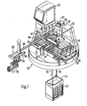
- the installation shown in FIG. 1 comprises a platform 20 capable of being moved vertically and of rotating around this vertical axis under the action of a stepping motor not shown.
- a chassis 22 carried by several feet erected on the platform.
- This chassis carries a cabin 24 which can house the surveillance personnel, and, above an opening 26 in the platform 20, a winch 28.
- This winch 28 is provided with two drums 30, 32 for winding cables 34 and 36 for lifting and lowering a pallet 42 through the opening 26 of the platform 20.
- the pallet 42 is, preferably mounted and lowered using a cage 40 as proposed in Luxembourg patent application No 86 189.
- FIG. 1 there are shown two pallets 44,46, in the depalletizing position.
- the pallets when lifted through the opening 26 using the winch 28 are supported by one of the two carriages 48 or 50 capable of reciprocating movements on a pair of rails 52, 54 arranged on either side of the opening 26.
- trays 56, 58 On either side of the central opening 26 are also provided two trays 56, 58 which, by the movement of the carriages 48 and 50 between the receiving position of the pallets above the opening 26 and their depalletizing position as shown in Figure 1, are engaged between the pallets 44 and 46 and their carrier carriages 48.50.
- These plates 56 and 58 are vertically movable under the action of hydraulic cylinders of which only the cylinder 60 associated with the plate 58 is shown, in order to be able to raise and lower each of the pallets 44,46 and thus reduce the amplitude of the vertical mobility of pliers 88.
- the installation further comprises a robot 62 consisting essentially of an automatic grapple 70 mounted at the end of a main arm 64.
- This arm 64 consists of two rods 66,68 sliding radially in two support beams 72 74 being part of the chassis 22.
- the radial displacement of the arm 64 is carried out under the action of a motor, not shown, the movements of which are coordinated with the control of the robot 62.
- the grapple 70 is preferably of the type described in Luxembourg patent application No 86 188.
- a tray 74 for storing the bricks.
- This plate 74 is mounted on the rod of a jack 76 which allows the vertical movement of the plate 74.
- the plate 74 is preferably capable of rotating, in a controlled manner, around its vertical axis, which is symbolized by an arrow.
- the installation also includes a depalletization machine represented overall by 78.
- This depalletization machine 78 consists of a support 80 which can slide radially in the direction of the arm 64 of the robot 62 in guide grooves 82, 84 arranged in the beams 72 and 74.
- a pivoting arm 86 is mounted by one of these ends on this support 80 so as to be able to pivot under the action of means not shown, about a vertical axis relative to this support 80.
- the opposite end of this pivoting arm 86 carries a clamp 88 which can also pivot around a vertical axis relative to the arm 86.
- the latter is furthermore vertically movable relative to the support 80, in order to be able to lift the bricks from the pallets 44, 46 by means of the clamp 88.
- the automaton 78 is in a position for gripping a brick located at the 'one of the ends of the pallet 46. After having grasped a brick, the automaton 78 must back up (see Figure 3) and at the same time its clamp 88 pivots in the counterclockwise direction, while its arm 86 pivots in the clockwise direction of a watch until complete alignment on the longitudinal axis of the plate 74 which is illustrated in FIG. 10. Once this alignment has been achieved, the automaton 78 can move forward to deposit the brick or bricks on the intermediate storage tray 74.
- Figures 4 and 5 illustrate the depalletization of a brick or a pair of bricks located on the same pallet 46, but at the opposite end of the depalletized brick in Figures 2 and 3.
- the automaton 78 After having grabbed the brick, the automaton 78 first recoils so that the brick does not strike the cable 34 during its rotation. From a certain position of the automaton 78 ′ the arm 86 and the clamp 88 are turned clockwise (see FIG. 5) until in an alignment position on the plate 74 and at from this position the automaton 78 is advanced in the direction of the plate 74 to deposit the brick thereon (see FIG. 10).
- the clamp 88 as illustrated by FIGS. 3 and 5, must rotate alternately in the opposite direction since the bricks, due to their taper, are oriented alternately in one direction and in the other on the pallets .
- FIGS. 6 to 9 illustrate the depalletization of bricks being, for FIGS. 6 and 7 at one of the ends of the pallet 44 and for FIGS. 8 and 9 at the opposite end of the pallet 44. It will be noted that, As a result of the position of the cables 34 and 36, the movements of the automaton 78 require less precautions for depalletizing the pallet 44 than for that of the pallet 46.
Landscapes
- Engineering & Computer Science (AREA)
- Chemical & Material Sciences (AREA)
- Mechanical Engineering (AREA)
- Materials Engineering (AREA)
- Metallurgy (AREA)
- Organic Chemistry (AREA)
- Manufacturing & Machinery (AREA)
- General Engineering & Computer Science (AREA)
- Furnace Housings, Linings, Walls, And Ceilings (AREA)
- Carbon Steel Or Casting Steel Manufacturing (AREA)
- Manipulator (AREA)
- Finishing Walls (AREA)
- Lining Or Joining Of Plastics Or The Like (AREA)
Priority Applications (1)
| Application Number | Priority Date | Filing Date | Title |
|---|---|---|---|
| AT87107127T ATE50632T1 (de) | 1986-06-05 | 1987-05-16 | Automatisierte vorrichtung zum ausmauern eines gefaesses. |
Applications Claiming Priority (2)
| Application Number | Priority Date | Filing Date | Title |
|---|---|---|---|
| LU86458A LU86458A1 (fr) | 1986-06-05 | 1986-06-05 | Installation automatisee pour briqueter la paroi interieure d'une enceinte |
| LU86458 | 1986-06-05 |
Publications (2)
| Publication Number | Publication Date |
|---|---|
| EP0248251A1 true EP0248251A1 (de) | 1987-12-09 |
| EP0248251B1 EP0248251B1 (de) | 1990-02-28 |
Family
ID=19730714
Family Applications (1)
| Application Number | Title | Priority Date | Filing Date |
|---|---|---|---|
| EP87107127A Expired - Lifetime EP0248251B1 (de) | 1986-06-05 | 1987-05-16 | Automatisierte Vorrichtung zum Ausmauern eines Gefässes |
Country Status (7)
| Country | Link |
|---|---|
| US (1) | US4786227A (de) |
| EP (1) | EP0248251B1 (de) |
| JP (1) | JP2584231B2 (de) |
| AT (1) | ATE50632T1 (de) |
| DE (1) | DE3761783D1 (de) |
| ES (1) | ES2013271B3 (de) |
| LU (1) | LU86458A1 (de) |
Cited By (1)
| Publication number | Priority date | Publication date | Assignee | Title |
|---|---|---|---|---|
| FR2638774A1 (fr) * | 1988-11-09 | 1990-05-11 | Wurth Paul Sa | Installation automatisee pour la pose d'une maconnerie sur une paroi |
Families Citing this family (9)
| Publication number | Priority date | Publication date | Assignee | Title |
|---|---|---|---|---|
| US5102280A (en) | 1989-03-07 | 1992-04-07 | Ade Corporation | Robot prealigner |
| LU87812A1 (fr) * | 1990-09-26 | 1992-05-25 | Arbed | Dispositif de manutention automatique d'objets |
| LU88144A1 (fr) * | 1992-07-07 | 1994-04-01 | Wurth Paul Sa | Installation pour garnir d'une maçonnerie de briques une paroi intérieure d'une enceinte |
| US8965571B2 (en) | 2010-08-12 | 2015-02-24 | Construction Robotics, Llc | Brick laying system |
| RU2700435C2 (ru) * | 2018-01-29 | 2019-09-17 | Алексей Александрович Спирин | Способ автоматизированной огнеупорной футеровки печей и роботизированный комплекс для его осуществления |
| WO2020139556A1 (en) * | 2018-12-26 | 2020-07-02 | Exxonmobil Research And Engineering Company | Remote inspection, removal, and installation of refractory |
| CN109680117B (zh) * | 2019-01-24 | 2020-12-11 | 山东钢铁股份有限公司 | 一种用于转炉砌筑的炉衬砖的运砖装置 |
| US12385265B2 (en) * | 2020-04-22 | 2025-08-12 | Fastbrick Ip Pty Ltd | Block transfer apparatus and improved clamping assembly for use therewith |
| US20240417985A1 (en) * | 2023-06-19 | 2024-12-19 | Obshchestvo s ogranichennoi otvetstvennostiu «Diginavis» | Device and method for erecting structures using building blocks |
Citations (6)
| Publication number | Priority date | Publication date | Assignee | Title |
|---|---|---|---|---|
| FR2070868A1 (de) * | 1969-12-15 | 1971-09-17 | Koninkl Nederland Ch | |
| GB1392960A (en) * | 1972-07-26 | 1975-05-07 | Combustion Eng | Automated bricklaying device |
| FR2314331A1 (fr) * | 1975-06-10 | 1977-01-07 | Voest Ag | Echafaudage pour le garnissage de recipients metallurgiques |
| DE3123582C1 (de) * | 1981-06-13 | 1982-11-04 | Mannesmann AG, 4000 Düsseldorf | Ausmauerungsvorrichtung für metallurgische Gefäße, insbesondere für Stahlwerkskonverter, Hochöfen u.dgl. |
| DE3413806C1 (de) * | 1984-04-12 | 1985-01-31 | Mannesmann AG, 4000 Düsseldorf | Einrichtung zum Ausmauern von metallurgischen Gefaessen,insbesondere von Stahlwerkskonvertern |
| FR2550984A1 (fr) * | 1983-07-07 | 1985-03-01 | Inst Rech Const Navale | Installation flexible de couples robot-porteurs |
Family Cites Families (4)
| Publication number | Priority date | Publication date | Assignee | Title |
|---|---|---|---|---|
| US3757484A (en) * | 1972-05-15 | 1973-09-11 | Combustion Enginc | Automated bricklaying device |
| LU85836A1 (fr) * | 1985-04-03 | 1986-11-05 | Wurth Paul Sa | Installation pour la pose d'un garnissage refractaire sur la paroi interieure d'une enceinte |
| LU86114A1 (fr) * | 1985-10-10 | 1987-06-02 | Wurth Paul Sa | Installation pour briqueter la paroi interieure d'une enceinte |
| LU86189A1 (fr) * | 1985-12-03 | 1987-07-24 | Wurth Paul Sa | Installation automatisee de briquetage de la paroi interieure d'une enceinte |
-
1986
- 1986-06-05 LU LU86458A patent/LU86458A1/fr unknown
-
1987
- 1987-05-16 ES ES87107127T patent/ES2013271B3/es not_active Expired - Lifetime
- 1987-05-16 AT AT87107127T patent/ATE50632T1/de not_active IP Right Cessation
- 1987-05-16 EP EP87107127A patent/EP0248251B1/de not_active Expired - Lifetime
- 1987-05-16 DE DE8787107127T patent/DE3761783D1/de not_active Expired - Lifetime
- 1987-06-04 JP JP62140739A patent/JP2584231B2/ja not_active Expired - Lifetime
- 1987-06-05 US US07/058,460 patent/US4786227A/en not_active Expired - Fee Related
Patent Citations (6)
| Publication number | Priority date | Publication date | Assignee | Title |
|---|---|---|---|---|
| FR2070868A1 (de) * | 1969-12-15 | 1971-09-17 | Koninkl Nederland Ch | |
| GB1392960A (en) * | 1972-07-26 | 1975-05-07 | Combustion Eng | Automated bricklaying device |
| FR2314331A1 (fr) * | 1975-06-10 | 1977-01-07 | Voest Ag | Echafaudage pour le garnissage de recipients metallurgiques |
| DE3123582C1 (de) * | 1981-06-13 | 1982-11-04 | Mannesmann AG, 4000 Düsseldorf | Ausmauerungsvorrichtung für metallurgische Gefäße, insbesondere für Stahlwerkskonverter, Hochöfen u.dgl. |
| FR2550984A1 (fr) * | 1983-07-07 | 1985-03-01 | Inst Rech Const Navale | Installation flexible de couples robot-porteurs |
| DE3413806C1 (de) * | 1984-04-12 | 1985-01-31 | Mannesmann AG, 4000 Düsseldorf | Einrichtung zum Ausmauern von metallurgischen Gefaessen,insbesondere von Stahlwerkskonvertern |
Cited By (2)
| Publication number | Priority date | Publication date | Assignee | Title |
|---|---|---|---|---|
| FR2638774A1 (fr) * | 1988-11-09 | 1990-05-11 | Wurth Paul Sa | Installation automatisee pour la pose d'une maconnerie sur une paroi |
| BE1003577A3 (fr) * | 1988-11-09 | 1992-04-28 | Wurth Paul Sa | Installation automatisee pour la pose d'une maconnerie sur une paroi. |
Also Published As
| Publication number | Publication date |
|---|---|
| JPS62293084A (ja) | 1987-12-19 |
| LU86458A1 (fr) | 1988-01-20 |
| DE3761783D1 (de) | 1990-04-05 |
| JP2584231B2 (ja) | 1997-02-26 |
| EP0248251B1 (de) | 1990-02-28 |
| ES2013271B3 (es) | 1990-05-01 |
| US4786227A (en) | 1988-11-22 |
| ATE50632T1 (de) | 1990-03-15 |
Similar Documents
| Publication | Publication Date | Title |
|---|---|---|
| EP0220543B1 (de) | Vorrichtung zum Zustellen der Wände eines Bauwerkes | |
| BE1003577A3 (fr) | Installation automatisee pour la pose d'une maconnerie sur une paroi. | |
| EP0040159B1 (de) | Manipulator | |
| BE1006857A3 (fr) | Installation pour garnir d'une maconnerie de briques une paroi interieure d'une enceinte. | |
| EP0230593B1 (de) | Automatisierte Anlage zum Ausmauern der Innenwand eines Gefässes | |
| FR2467465A1 (fr) | Machine de rechargement pour un reacteur nucleaire | |
| EP3456601B1 (de) | Fördersystem eines länglichen bauelements, förderfahrzeug, das mit einem solchen system ausgestattet ist | |
| EP0248251B1 (de) | Automatisierte Vorrichtung zum Ausmauern eines Gefässes | |
| EP0451061A1 (de) | Fernbetätigte, motorgetriebene Lastgreifeinrichtung | |
| EP2167251A2 (de) | Vorrichtung zur handhabung einer last, z. b. einer eisenblechspule | |
| FR2623891A1 (fr) | Installation pour briqueter la paroi interieure d'une enceinte | |
| EP0198267B1 (de) | Einrichtung zum Anbringen einer feuerfesten Auskleidung an der Innenwand eines Gefässes | |
| FR3045027A1 (fr) | Dispositif et procede de recuperation d'un colis stocke dans un local | |
| EP0226075B1 (de) | Automatisierte Anlage zum Ausmauern der Innenwand eines Gefässes | |
| EP0263979B1 (de) | Anlage zum Ausmauern der Innenwand eines Gefässes | |
| EP0533547A1 (de) | Verstellbarer Handhabungsgreifer für ein Kernbrennelement | |
| FR3077228A1 (fr) | Systeme d’aide au dressage et a la depose d’element de construction longitudinal et vehicule de manutention d’element de construction longitudinal equipe d’un tel systeme | |
| FR2562523A1 (fr) | Systeme de transfert d'objets entre deux dispositifs dont l'un comporte un ensemble de plateaux verticalement espaces | |
| FR2610235A1 (fr) | Appareil de transport et de manutention de charges, comprenant un chariot sans conducteur a fourche de levage | |
| FR2491891A1 (fr) | Procede de manutention et de stockage d'objets a symetrie axiale, notamment de tourets et dispositif trans-stockeur de mise en oeuvre | |
| WO2020181380A1 (fr) | Dispositif de manutention destine a convoyer un outil d'intervention sur une cuve d'electrolyse | |
| EP0463913A1 (de) | Automatische Fördervorrichtung für mehrere Positionier- oder Verbindungselemente | |
| EP1060831A1 (de) | Werkstücktransfervorrichtung | |
| FR2669312A1 (fr) | Magasin de stockage automatique. | |
| FR2557551A1 (fr) | Pince automatique pour la manutention et le levage de charges |
Legal Events
| Date | Code | Title | Description |
|---|---|---|---|
| PUAI | Public reference made under article 153(3) epc to a published international application that has entered the european phase |
Free format text: ORIGINAL CODE: 0009012 |
|
| AK | Designated contracting states |
Kind code of ref document: A1 Designated state(s): AT BE DE ES FR GB IT NL SE |
|
| 17P | Request for examination filed |
Effective date: 19880315 |
|
| 17Q | First examination report despatched |
Effective date: 19890428 |
|
| GRAA | (expected) grant |
Free format text: ORIGINAL CODE: 0009210 |
|
| AK | Designated contracting states |
Kind code of ref document: B1 Designated state(s): AT BE DE ES FR GB IT NL SE |
|
| REF | Corresponds to: |
Ref document number: 50632 Country of ref document: AT Date of ref document: 19900315 Kind code of ref document: T |
|
| REF | Corresponds to: |
Ref document number: 3761783 Country of ref document: DE Date of ref document: 19900405 |
|
| GBT | Gb: translation of ep patent filed (gb section 77(6)(a)/1977) | ||
| ITF | It: translation for a ep patent filed | ||
| PLBE | No opposition filed within time limit |
Free format text: ORIGINAL CODE: 0009261 |
|
| STAA | Information on the status of an ep patent application or granted ep patent |
Free format text: STATUS: NO OPPOSITION FILED WITHIN TIME LIMIT |
|
| 26N | No opposition filed | ||
| ITTA | It: last paid annual fee | ||
| EAL | Se: european patent in force in sweden |
Ref document number: 87107127.0 |
|
| PGFP | Annual fee paid to national office [announced via postgrant information from national office to epo] |
Ref country code: GB Payment date: 19960417 Year of fee payment: 10 Ref country code: FR Payment date: 19960417 Year of fee payment: 10 |
|
| PGFP | Annual fee paid to national office [announced via postgrant information from national office to epo] |
Ref country code: DE Payment date: 19960419 Year of fee payment: 10 |
|
| PGFP | Annual fee paid to national office [announced via postgrant information from national office to epo] |
Ref country code: BE Payment date: 19960507 Year of fee payment: 10 |
|
| PGFP | Annual fee paid to national office [announced via postgrant information from national office to epo] |
Ref country code: ES Payment date: 19960508 Year of fee payment: 10 |
|
| PGFP | Annual fee paid to national office [announced via postgrant information from national office to epo] |
Ref country code: SE Payment date: 19960521 Year of fee payment: 10 |
|
| PGFP | Annual fee paid to national office [announced via postgrant information from national office to epo] |
Ref country code: NL Payment date: 19960529 Year of fee payment: 10 |
|
| PGFP | Annual fee paid to national office [announced via postgrant information from national office to epo] |
Ref country code: AT Payment date: 19960530 Year of fee payment: 10 |
|
| PG25 | Lapsed in a contracting state [announced via postgrant information from national office to epo] |
Ref country code: GB Effective date: 19970516 Ref country code: AT Effective date: 19970516 |
|
| PG25 | Lapsed in a contracting state [announced via postgrant information from national office to epo] |
Ref country code: SE Effective date: 19970517 Ref country code: ES Free format text: LAPSE BECAUSE OF NON-PAYMENT OF DUE FEES Effective date: 19970517 |
|
| PG25 | Lapsed in a contracting state [announced via postgrant information from national office to epo] |
Ref country code: BE Effective date: 19970531 |
|
| BERE | Be: lapsed |
Owner name: S.A. PAUL WURTH Effective date: 19970531 |
|
| PG25 | Lapsed in a contracting state [announced via postgrant information from national office to epo] |
Ref country code: NL Effective date: 19971201 |
|
| GBPC | Gb: european patent ceased through non-payment of renewal fee |
Effective date: 19970516 |
|
| PG25 | Lapsed in a contracting state [announced via postgrant information from national office to epo] |
Ref country code: FR Free format text: LAPSE BECAUSE OF NON-PAYMENT OF DUE FEES Effective date: 19980130 |
|
| EUG | Se: european patent has lapsed |
Ref document number: 87107127.0 |
|
| NLV4 | Nl: lapsed or anulled due to non-payment of the annual fee |
Effective date: 19971201 |
|
| PG25 | Lapsed in a contracting state [announced via postgrant information from national office to epo] |
Ref country code: DE Free format text: LAPSE BECAUSE OF NON-PAYMENT OF DUE FEES Effective date: 19980203 |
|
| REG | Reference to a national code |
Ref country code: FR Ref legal event code: ST |
|
| REG | Reference to a national code |
Ref country code: ES Ref legal event code: FD2A Effective date: 19990201 |
|
| PG25 | Lapsed in a contracting state [announced via postgrant information from national office to epo] |
Ref country code: IT Free format text: LAPSE BECAUSE OF NON-PAYMENT OF DUE FEES;WARNING: LAPSES OF ITALIAN PATENTS WITH EFFECTIVE DATE BEFORE 2007 MAY HAVE OCCURRED AT ANY TIME BEFORE 2007. THE CORRECT EFFECTIVE DATE MAY BE DIFFERENT FROM THE ONE RECORDED. Effective date: 20050516 |