EP0248320A1 - Dispositif pour la détection des courants de défaut - Google Patents
Dispositif pour la détection des courants de défaut Download PDFInfo
- Publication number
- EP0248320A1 EP0248320A1 EP87107606A EP87107606A EP0248320A1 EP 0248320 A1 EP0248320 A1 EP 0248320A1 EP 87107606 A EP87107606 A EP 87107606A EP 87107606 A EP87107606 A EP 87107606A EP 0248320 A1 EP0248320 A1 EP 0248320A1
- Authority
- EP
- European Patent Office
- Prior art keywords
- current
- voltage
- fault
- currents
- arrangement
- Prior art date
- Legal status (The legal status is an assumption and is not a legal conclusion. Google has not performed a legal analysis and makes no representation as to the accuracy of the status listed.)
- Withdrawn
Links
- 238000004804 winding Methods 0.000 claims abstract description 26
- 230000005284 excitation Effects 0.000 claims abstract description 16
- 239000004020 conductor Substances 0.000 claims description 7
- 230000005291 magnetic effect Effects 0.000 claims description 7
- 239000003990 capacitor Substances 0.000 claims description 3
- 238000012544 monitoring process Methods 0.000 claims description 2
- 238000012806 monitoring device Methods 0.000 abstract 2
- 230000006698 induction Effects 0.000 description 5
- 230000007423 decrease Effects 0.000 description 3
- XEEYBQQBJWHFJM-UHFFFAOYSA-N Iron Chemical compound [Fe] XEEYBQQBJWHFJM-UHFFFAOYSA-N 0.000 description 2
- PXHVJJICTQNCMI-UHFFFAOYSA-N Nickel Chemical compound [Ni] PXHVJJICTQNCMI-UHFFFAOYSA-N 0.000 description 2
- 238000001514 detection method Methods 0.000 description 2
- 230000004907 flux Effects 0.000 description 2
- 230000005415 magnetization Effects 0.000 description 2
- 239000000463 material Substances 0.000 description 2
- 230000035699 permeability Effects 0.000 description 2
- ZOXJGFHDIHLPTG-UHFFFAOYSA-N Boron Chemical compound [B] ZOXJGFHDIHLPTG-UHFFFAOYSA-N 0.000 description 1
- PWHULOQIROXLJO-UHFFFAOYSA-N Manganese Chemical compound [Mn] PWHULOQIROXLJO-UHFFFAOYSA-N 0.000 description 1
- 241001465754 Metazoa Species 0.000 description 1
- ZOKXTWBITQBERF-UHFFFAOYSA-N Molybdenum Chemical compound [Mo] ZOKXTWBITQBERF-UHFFFAOYSA-N 0.000 description 1
- 239000000654 additive Substances 0.000 description 1
- 239000000956 alloy Substances 0.000 description 1
- 229910045601 alloy Inorganic materials 0.000 description 1
- 229910052796 boron Inorganic materials 0.000 description 1
- 230000008859 change Effects 0.000 description 1
- 239000010941 cobalt Substances 0.000 description 1
- 229910017052 cobalt Inorganic materials 0.000 description 1
- GUTLYIVDDKVIGB-UHFFFAOYSA-N cobalt atom Chemical compound [Co] GUTLYIVDDKVIGB-UHFFFAOYSA-N 0.000 description 1
- 239000013078 crystal Substances 0.000 description 1
- 230000001419 dependent effect Effects 0.000 description 1
- 238000011156 evaluation Methods 0.000 description 1
- 239000003302 ferromagnetic material Substances 0.000 description 1
- 230000007274 generation of a signal involved in cell-cell signaling Effects 0.000 description 1
- 229910052742 iron Inorganic materials 0.000 description 1
- 229910052748 manganese Inorganic materials 0.000 description 1
- 239000011572 manganese Substances 0.000 description 1
- 239000005300 metallic glass Substances 0.000 description 1
- 229910052750 molybdenum Inorganic materials 0.000 description 1
- 239000011733 molybdenum Substances 0.000 description 1
- 229910052759 nickel Inorganic materials 0.000 description 1
- 230000004044 response Effects 0.000 description 1
- 229910052710 silicon Inorganic materials 0.000 description 1
- 239000010703 silicon Substances 0.000 description 1
- 230000007704 transition Effects 0.000 description 1
Images
Classifications
-
- H—ELECTRICITY
- H02—GENERATION; CONVERSION OR DISTRIBUTION OF ELECTRIC POWER
- H02H—EMERGENCY PROTECTIVE CIRCUIT ARRANGEMENTS
- H02H3/00—Emergency protective circuit arrangements for automatic disconnection directly responsive to an undesired change from normal electric working condition with or without subsequent reconnection ; integrated protection
- H02H3/26—Emergency protective circuit arrangements for automatic disconnection directly responsive to an undesired change from normal electric working condition with or without subsequent reconnection ; integrated protection responsive to difference between voltages or between currents; responsive to phase angle between voltages or between currents
- H02H3/32—Emergency protective circuit arrangements for automatic disconnection directly responsive to an undesired change from normal electric working condition with or without subsequent reconnection ; integrated protection responsive to difference between voltages or between currents; responsive to phase angle between voltages or between currents involving comparison of the voltage or current values at corresponding points in different conductors of a single system, e.g. of currents in go and return conductors
- H02H3/33—Emergency protective circuit arrangements for automatic disconnection directly responsive to an undesired change from normal electric working condition with or without subsequent reconnection ; integrated protection responsive to difference between voltages or between currents; responsive to phase angle between voltages or between currents involving comparison of the voltage or current values at corresponding points in different conductors of a single system, e.g. of currents in go and return conductors using summation current transformers
- H02H3/332—Emergency protective circuit arrangements for automatic disconnection directly responsive to an undesired change from normal electric working condition with or without subsequent reconnection ; integrated protection responsive to difference between voltages or between currents; responsive to phase angle between voltages or between currents involving comparison of the voltage or current values at corresponding points in different conductors of a single system, e.g. of currents in go and return conductors using summation current transformers with means responsive to DC component in the fault current
Definitions
- the invention relates to an arrangement for detecting fault currents with a summation current transformer, the primary circuit of which is formed by mains conductors, the secondary circuit of which contains a holding magnet and whose magnetic core is provided with a bias winding through which an excitation current flows.
- the mains conductors can be passed as primary conductors through a summation current transformer, the secondary winding of which is arranged in a display or tripping circuit.
- a summation current transformer the secondary winding of which is arranged in a display or tripping circuit.
- the sum of the primary currents passing through the summation current transformer is zero. No magnetic flux is generated in the core of the converter and therefore no voltage is induced on the secondary winding of the converter. If a fault current occurs, the sum of the currents does not equal zero and a current flows in the secondary circuit of the converter, which can act to trigger a circuit breaker.
- the summation current transformer works as a transformer. The arrangement is not suitable for the detection of smooth DC residual currents.
- Electronic residual current circuit breakers generally also use summation current transformers, in which the magnetization state generated by the fault current is measured. This changes both with AC residual currents and with DC residual currents, so that these residual current switches are AC / DC sensitive. However, this requires a supply voltage and evaluation electronics. These switches only work depending on the voltage.
- the invention has for its object to provide an arrangement for detecting any fault currents, which also works independently of the voltage;
- known voltage-independent residual current circuit breakers are to be made sensitive to all currents by an additional voltage-dependent signal generation and signal processing.
- the residual current properties should remain unchanged.
- a known arrangement for detecting fault currents contains a summation current transformer which, in addition to its secondary winding, is also provided with a bias winding which is connected to a voltage source with a higher frequency.
- the voltage on the bias winding is used to detect DC residual currents.
- a filter element When a filter element is switched on, the voltage generated by the alternating fault current is suppressed, so that the voltage induced by the alternating current represents a measure of the inductance of the bias winding.
- This arrangement can thus do not operate a circuit breaker regardless of voltage (DE-OS 28 51 381).
- This arrangement triggers the circuit breaker as soon as the voltage induced by the excitation current in the secondary circuit falls below a predetermined limit value or becomes zero. It thus forms an AC / DC sensitive residual current circuit breaker, which switches residual currents that are not smooth DC residual currents, regardless of voltage, and detects pure DC residual currents with the aid of its excitation current.
- the summation current transformer receives the additional pre-magnetization winding, which is fed with an excitation current.
- the amplitude of this excitation current is set small compared to a fault current. Its frequency is at least 200 Hz, preferably at least 500 Hz, and in particular at least 1000 Hz. The small current amplitude and the increased frequency of the excitation current avoid influencing normal residual current circuit breaker properties.
- the summation current transformer has a core with high permeability and preferably a flat hysteresis loop, a so-called F loop, and thus a low remanence. If a DC fault current occurs, the total current transformer runs through the flat hysteresis loop with increasing fault current. During the transition from the steep branch of the hysteresis loop to the saturation induction, the induction stroke generated by the auxiliary alternating current decreases more and more until it becomes practically zero. The voltage induced thereby decreases proportionally to the induction stroke and, when falling below a predetermined limit value, actuates the voltage monitor, which actuates a trigger for a circuit breaker.
- the core of the summation current transformer consists at least in part of amorphous, ferromagnetic material, an alloy with metallic properties, but without a crystal lattice, which is therefore also generally referred to as metallic glass.
- the main components of this material can be iron, nickel and cobalt with crystallization-retarding additives, especially silicon and boron as well as possibly molybdenum and manganese (VITROVAC).
- VITROVAC molybdenum and manganese
- a core with a flat hysteresis loop a so-called F loop
- VTROVAC 6025 F the remanence of which generally does not substantially exceed about 25% of the saturation induction and is preferably only about 10% at most. This provides a sufficient induction stroke for the detection of pulsating DC residual currents.
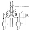
- the magnetic core 3 of a summation current transformer 2 with a Primary winding 4 and a secondary winding 5 and an additional bias winding 6 are provided.
- a network conductor L and a center conductor N are provided as the primary winding.
- the power line contains a circuit breaker 8, the holding magnet 9 of which is arranged in the secondary circuit of the summation current transformer 2.
- a capacitor 10 can preferably also be provided, the capacitance of which forms a series resonant circuit with the inductance of the secondary winding 5.
- the bias winding 6 is connected to a power supply 12, which can be fed, for example, from a voltage source for 220 V AC.
- the power supply unit 12 supplies the bias winding 6 with an excitation current I e with a predetermined amplitude and increased frequency, preferably 1000 Hz.
- a voltage monitor 14 is provided, which can also be supplied by a voltage source for 220 V alternating current.
- the input E of the voltage monitor 14 is the secondary winding 5 and the output A of the voltage monitor 14 is connected in parallel with the holding magnet 9.
- the voltage monitor 14 actuates the holding magnet 9 of the circuit breaker 8 as soon as the voltage on the secondary winding 5 falls below a predetermined limit value.
- the monitoring 14 can contain a filter which only allows the voltage component of the secondary winding to pass through with the frequency of the excitation current I e of the bias winding 6.
- the decrease in the secondary voltage with increasing fault current in the primary winding is detected by the voltage monitor 14. It switches the holding magnet 9 as soon as it detects that the voltage signal induced by the excitation current I e is approaching a predetermined, adjustable limit value. This limit value is set so that it is reached at the usual response values of residual current circuit breakers, for example a residual current of 30 mA or 50 mA.
- the voltage monitor 14 thus acts as a voltage monitor for the secondary voltage. This device thus only reacts to the excitation current I e and is independent of the switching on of the network.
Landscapes
- Engineering & Computer Science (AREA)
- Power Engineering (AREA)
- Transformers For Measuring Instruments (AREA)
- Testing Of Short-Circuits, Discontinuities, Leakage, Or Incorrect Line Connections (AREA)
- Measuring Instrument Details And Bridges, And Automatic Balancing Devices (AREA)
- Emergency Protection Circuit Devices (AREA)
Applications Claiming Priority (2)
| Application Number | Priority Date | Filing Date | Title |
|---|---|---|---|
| DE3618924 | 1986-06-05 | ||
| DE3618924 | 1986-06-05 |
Publications (1)
| Publication Number | Publication Date |
|---|---|
| EP0248320A1 true EP0248320A1 (fr) | 1987-12-09 |
Family
ID=6302332
Family Applications (1)
| Application Number | Title | Priority Date | Filing Date |
|---|---|---|---|
| EP87107606A Withdrawn EP0248320A1 (fr) | 1986-06-05 | 1987-05-25 | Dispositif pour la détection des courants de défaut |
Country Status (2)
| Country | Link |
|---|---|
| EP (1) | EP0248320A1 (fr) |
| JP (1) | JPS633616A (fr) |
Cited By (4)
| Publication number | Priority date | Publication date | Assignee | Title |
|---|---|---|---|---|
| DE19622409A1 (de) * | 1996-06-04 | 1997-12-11 | Kopp Heinrich Ag | Fehlerstromschutzschalter |
| DE102005054544A1 (de) * | 2005-11-14 | 2007-05-31 | Ean Elektroschaltanlagen Gmbh | Verfahren und Einrichtung zur Ortung von Isolationsfehlern in isolierten ungeerdeten Wechselspannungsnetzen |
| CN109375134A (zh) * | 2018-10-08 | 2019-02-22 | 中国大唐集团科学技术研究院有限公司火力发电技术研究院 | 发电机出口电压互感器内部故障在线监测方法及系统 |
| DE102024208883A1 (de) * | 2024-09-17 | 2026-03-19 | Volkswagen Aktiengesellschaft | Ladegerät zum Laden eines Elektro- oder Hybridfahrzeugs |
Families Citing this family (1)
| Publication number | Priority date | Publication date | Assignee | Title |
|---|---|---|---|---|
| CN106443120A (zh) * | 2016-10-10 | 2017-02-22 | 华北电力大学(保定) | 差分式的直流电流互感器控制方法和直流电流互感器 |
Citations (5)
| Publication number | Priority date | Publication date | Assignee | Title |
|---|---|---|---|---|
| DE2036497A1 (de) * | 1970-07-23 | 1972-02-03 | Siemens Ag | Fehlerstromschutzschalter |
| DE2555221A1 (de) * | 1975-12-09 | 1977-06-23 | Bbc Brown Boveri & Cie | Verfahren zur erfassung von fehlerstroemen beliebiger art |
| DE2555303A1 (de) * | 1975-12-09 | 1977-06-23 | Bbc Brown Boveri & Cie | Fehlerstromschutzschaltung |
| DE2713043A1 (de) * | 1977-03-24 | 1978-09-28 | Siemens Ag | Fehlerstrom-abschalteinrichtung |
| US4320433A (en) * | 1980-03-21 | 1982-03-16 | Fuji Electric Co., Ltd. | Earth-leakage-current circuit breaker system |
-
1987
- 1987-05-25 EP EP87107606A patent/EP0248320A1/fr not_active Withdrawn
- 1987-05-29 JP JP62134760A patent/JPS633616A/ja active Pending
Patent Citations (5)
| Publication number | Priority date | Publication date | Assignee | Title |
|---|---|---|---|---|
| DE2036497A1 (de) * | 1970-07-23 | 1972-02-03 | Siemens Ag | Fehlerstromschutzschalter |
| DE2555221A1 (de) * | 1975-12-09 | 1977-06-23 | Bbc Brown Boveri & Cie | Verfahren zur erfassung von fehlerstroemen beliebiger art |
| DE2555303A1 (de) * | 1975-12-09 | 1977-06-23 | Bbc Brown Boveri & Cie | Fehlerstromschutzschaltung |
| DE2713043A1 (de) * | 1977-03-24 | 1978-09-28 | Siemens Ag | Fehlerstrom-abschalteinrichtung |
| US4320433A (en) * | 1980-03-21 | 1982-03-16 | Fuji Electric Co., Ltd. | Earth-leakage-current circuit breaker system |
Cited By (5)
| Publication number | Priority date | Publication date | Assignee | Title |
|---|---|---|---|---|
| DE19622409A1 (de) * | 1996-06-04 | 1997-12-11 | Kopp Heinrich Ag | Fehlerstromschutzschalter |
| DE102005054544A1 (de) * | 2005-11-14 | 2007-05-31 | Ean Elektroschaltanlagen Gmbh | Verfahren und Einrichtung zur Ortung von Isolationsfehlern in isolierten ungeerdeten Wechselspannungsnetzen |
| DE102005054544B4 (de) * | 2005-11-14 | 2012-08-30 | Ean Elektroschaltanlagen Gmbh | Verfahren und Einrichtung zur Ortung von Isolationsfehlern in isolierten ungeerdeten Wechselspannungsnetzen |
| CN109375134A (zh) * | 2018-10-08 | 2019-02-22 | 中国大唐集团科学技术研究院有限公司火力发电技术研究院 | 发电机出口电压互感器内部故障在线监测方法及系统 |
| DE102024208883A1 (de) * | 2024-09-17 | 2026-03-19 | Volkswagen Aktiengesellschaft | Ladegerät zum Laden eines Elektro- oder Hybridfahrzeugs |
Also Published As
| Publication number | Publication date |
|---|---|
| JPS633616A (ja) | 1988-01-08 |
Similar Documents
| Publication | Publication Date | Title |
|---|---|---|
| DE69412938T2 (de) | Erdschlussschalter | |
| EP3226013B1 (fr) | Capteur de courant différentiel | |
| DE2261004A1 (de) | Erdschlussfehler-anzeigeeinrichtung, sowie diese verwendender stromkreisunterbrecher | |
| DE112005001167B4 (de) | Differenzstromdetektion | |
| DE102013106099A1 (de) | Stromsensoranordnung | |
| EP0273255B1 (fr) | Interrupteur de protection à courant différentiel | |
| EP1277264B1 (fr) | Commutateur de protection a courant de defaut et procede pour tester le fonctionnement | |
| DE2851381C2 (de) | Fehlerstrom-Schutzschaltung für Gleich- und/oder Wechselstrom | |
| EP1212821B1 (fr) | Dispositif de protection contre les courants de fuite sensible a tout courant | |
| EP0248320A1 (fr) | Dispositif pour la détection des courants de défaut | |
| DE3543985A1 (de) | Anordnung zum erfassen von fehlerstroemen | |
| DE3723568A1 (de) | Differenzstromschutzschalter | |
| DE2731453C3 (de) | Erdschlußdetektor | |
| EP1478070B1 (fr) | Dispositif de protection sensible à tout courant de défaut | |
| DE2555255C3 (de) | Einrichtung zur Erfassung von Fehlerströmen | |
| DE2526649A1 (de) | Erdschlusschutzeinrichtung | |
| EP0627133B1 (fr) | Disjoncteur de courant de fuite | |
| DE3543948C2 (fr) | ||
| DE4128961C1 (en) | Detecting short circuit to earth in pulse inverter - using square wave HF voltage source in evaluation circuit to operate protection circuit when toroidal transformer saturates | |
| DE3718183C2 (de) | Differenzstromschutzschalter | |
| DE2715219C2 (fr) | ||
| DE1905505B2 (de) | Fehlerstromschutzschalter | |
| DE2124178B2 (de) | Schutzeinrichtung zum feststellen von erdschluss-leckstroemen | |
| EP0782761B1 (fr) | Interrupteur de protection differentielle pourvu d'un materiau pour circuit magnetique special | |
| DE4019810A1 (de) | Verfahren zum nachweis eines wechselstromes oder gleichstromes |
Legal Events
| Date | Code | Title | Description |
|---|---|---|---|
| PUAI | Public reference made under article 153(3) epc to a published international application that has entered the european phase |
Free format text: ORIGINAL CODE: 0009012 |
|
| AK | Designated contracting states |
Kind code of ref document: A1 Designated state(s): AT BE CH DE ES FR GB GR IT LI NL |
|
| STAA | Information on the status of an ep patent application or granted ep patent |
Free format text: STATUS: THE APPLICATION HAS BEEN WITHDRAWN |
|
| 18W | Application withdrawn |
Withdrawal date: 19871214 |
|
| RIN1 | Information on inventor provided before grant (corrected) |
Inventor name: POHL, FRITZ, DIPL.-PHYS. |