EP0248406A2 - Appareil de va-et-vient pour fil - Google Patents
Appareil de va-et-vient pour fil Download PDFInfo
- Publication number
- EP0248406A2 EP0248406A2 EP87107972A EP87107972A EP0248406A2 EP 0248406 A2 EP0248406 A2 EP 0248406A2 EP 87107972 A EP87107972 A EP 87107972A EP 87107972 A EP87107972 A EP 87107972A EP 0248406 A2 EP0248406 A2 EP 0248406A2
- Authority
- EP
- European Patent Office
- Prior art keywords
- yarn
- winding
- bobbin
- package
- traverse
- Prior art date
- Legal status (The legal status is an assumption and is not a legal conclusion. Google has not performed a legal analysis and makes no representation as to the accuracy of the status listed.)
- Granted
Links
Images




Classifications
-
- B—PERFORMING OPERATIONS; TRANSPORTING
- B65—CONVEYING; PACKING; STORING; HANDLING THIN OR FILAMENTARY MATERIAL
- B65H—HANDLING THIN OR FILAMENTARY MATERIAL, e.g. SHEETS, WEBS, CABLES
- B65H54/00—Winding, coiling, or depositing filamentary material
- B65H54/02—Winding and traversing material on to reels, bobbins, tubes, or like package cores or formers
- B65H54/38—Arrangements for preventing ribbon winding ; Arrangements for preventing irregular edge forming, e.g. edge raising or yarn falling from the edge
- B65H54/381—Preventing ribbon winding in a precision winding apparatus, i.e. with a constant ratio between the rotational speed of the bobbin spindle and the rotational speed of the traversing device driving shaft
- B65H54/383—Preventing ribbon winding in a precision winding apparatus, i.e. with a constant ratio between the rotational speed of the bobbin spindle and the rotational speed of the traversing device driving shaft in a stepped precision winding apparatus, i.e. with a constant wind ratio in each step
-
- B—PERFORMING OPERATIONS; TRANSPORTING
- B65—CONVEYING; PACKING; STORING; HANDLING THIN OR FILAMENTARY MATERIAL
- B65H—HANDLING THIN OR FILAMENTARY MATERIAL, e.g. SHEETS, WEBS, CABLES
- B65H2701/00—Handled material; Storage means
- B65H2701/30—Handled filamentary material
- B65H2701/31—Textiles threads or artificial strands of filaments
Definitions
- the present invention relates in general to a yarn traverse apparatus for winding a continuous yarn or thread on the bobbin, and in particular to an improved yarn traverse apparatus which can prevent an occurrence of a so-called ribbonning during the yarn winding operation.
- a yarn traverse apparatus for winding a yarn on a bobbin, comprising setting means for setting a limit value of a leash angle of the yarn, a traverse stroke of a package wound on the bobbin, a width of the yarn wound on the bobbin, and a ribbon occurrence region; bobbin rotational number detecting means for detecting the number of rotations of the bobbin on which the package is wound; winding-speed detecting means for detecting a winding speed of the yarn; package-diameter operation means for calculating a diameter of the package in accordance with the number of rotations of the bobbin detected by the bobbin rotational number detecting means and the winding speed of the yarn detected by said winding-speed detecting means; winding-ratio operation means for calculating a winding ratio in accordance with the number of turns of the yarn when a distance of two traverse strokes is divided by the yarn width and the number of turns of the yarn when one pitch
- the yarn In winding a continuous yarn or thread at high speed on a bobbin and forming a yarn package on the bobbin, the yarn is generally wound with a constant leash angle of the yarn during the yarn winding operation.
- a ratio of the number of rotations of the bobbin to the number of yarn traversing strokes hereinafter referred to as a "winding ratio"
- the yarn to be wound tends to be wound on a turn of the yarn previously wound on the bobbin, thereby making the outer circumferential surface of the yarn package uneven and forming circumferential rib portions on the yarn package (called “ribbonning").
- Such a ribbonning phenomenon may cause the outer circumferential layer of the yarn package to slide toward the center or a vibration during the yarn winding operation. If the vibration is caused by the ribbonning phenomenon, the yarn tends to be unwound from the layer of the circumferential rib portion formed previous to the rib portion being now formed.
- an important object of the present invention to provide an improved yarn traverse apparatus which is capable of enhancing quality of the yarn wound on the bobbin and which eliminates the aforementioned disadvantages attendant with the prior art.
- the object of the present invention is achieved by varying the winding ratio in steps so that an occurrence of ribbonning and the like is avoided.
- a cylindrical bobbin is rotatably supported on a bobbin spindle 1.
- the bobbin 2 is adapted to have a continuous yarn or thread wound thereon into a suitable form of yarn package 3.
- a friction roller 4 which is carried on a roller shaft 4a and which is rotatable on the shaft 4a.
- the yarn to be wound on the bobbin 2 is fed through a yarn traversing cam 5 adapted to move the yarn alternately in opposite directions parallel with the center axis of the bobbin 2 so that the yarn is distributed uniformally throughout the length of the yarn package 3.
- the spindle 1 of the bobbin 2 is connected through a drive shaft 6 to an induction motor 7 so that the bobbin 2 is driven for rotation about the spindle 1.
- the induction motor 7 is connected with an invertor 8 and rotates with the frequency corresponding to the output of the invertor 8.
- the yarn traversing cam 5 is connected through a drive shaft 9 to an induction motor 10 so that it is driven for rotation about the drive shaft 9.
- the induction motor 10 is connected with an invertor 11 and rotates with the frequency corresponding to the output of the invertor 11.
- the yarn traversing cam 5 rotates with the frequency corresponding to the output of the invertor 11.
- the aforementioned yarn traversing cam 5, drive shaft 9, induction motor 10 and invertor 11 as a whole constitute a traverse mechanism indicated generally by reference numeral 12.
- each of the invertors 8 and 11 is controlled by command signals from a controller 13 to which signals from first and second electromagnetic pick-ups 14 and 15 are inputted.
- the first electromagnetic pick-up 14 is disposed adjacent a gear 16 fixed on the shaft 4a of the friction roller 4 and detects the number of rotations of the gear 16. As a result, the number of rotations Nc of the friction roller 4 is detected indirectly from the number of rotations of the gear 16.
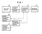
- the first electromagnetic pick-up 14 and the gear 16 of the friction roller 4 as a whole constitute winding-speed detecting means for detecting a winding speed of the yarn, which is designated generally by reference numeral 17.
- the second electromagnetic pick-up 15 is disposed adjacent a gear 18 fixed on the drive shaft 9 of the yarn traversing cam 5 and detects the number of rotations of the gear 18. As a result, the number of rotations Nt of the yarn traversing cam 5 is detected indirectly from the number of rotations of the gear 18.
- the second electromagnetic pick-up 15 and the gear 18 of the yarn traversing cam 5 as a whole constitute cam rotational number detecting means for detecting the number of rotations of the yarn traversing cam 5, which is designated generally by reference numeral 19.
- a third electromagnetic pick-up 27 is disposed adjacent a gear 26 fixed on the drive shaft 6 of the bobbin 2 and detects the number of rotations Nb of the bobbin 2.
- the third electromagnetic pick-up 27 and the gear 26 of the drive shaft 6 as a whole constitute bobbin rotational number detecting means for detecting the number of rotations of the bobbin 2, which is designated generally by reference numeral 28.
- a setting device or means 20 which is adapted to set an upper limit value ⁇ H of a leash angle (FIG. 4) of the yarn, a traverse stroke S of the package to be wound, a width w of the yarn to be wound, and a ribbon occurrence region Y.
- ⁇ H of a leash angle (FIG. 4) of the yarn a traverse stroke S of the package to be wound, a width w of the yarn to be wound, and a ribbon occurrence region Y.
- These values may be set manually by an operator of a winding machine or automatically by the setting device 20 itself on the basis of information from the controller 13.
- the controller 13 has a package-diameter operation means, a winding-ratio operation means and a traverse operation means, and comprises a central processing unit 21 labelled as "CPU”, a read-only memory 22 labelled as “ROM”, a random access memory 23 labelled as “RAM” and an input-output port 24 labelled as "I/O".
- the CPU 21 has received therein external datum which are necessary in accordance with programs read on the ROM 22, and processes values necessary for the yarn traversing control, giving and receiving datum between the CPU 21 and the RAM 23. The processed values are transferred from the CPU 21 to the I/O port 24.
- the I/O 24 receives signals from the electromagnetic pick-ups 14, 15 and 27 and a signal from the setting device 20 and delivers command signals to the invertors 8 and 11 and an indicative signal S H to an indicator 25.
- the ROM 22 has stored therein programs and datum in the CPU 21.
- the RAM 23 temporary memorizes external information and datum to be used in operation.
- the indicator 25 indicates information necessary for the winding control on the basis of the indicative signal S H delivered from the controller 13.
- FIGS. 3 and 5 are respectively block diagrams showing a program for the yarn traversing control.
- the yarn traversing control program according to the present invention consists of a winding-ratio arithmetic operation program indicated by "JOB-1" in FIG. 3 and a traverse number arithmetic operation program indicated by "JOB-2" in FIG. 5.
- the winding-ratio program JOB-1 and the traverse number program JOB-2 are processed in the recited order.
- the winding-ratio program JOB-1 commences by an input commencement operation to the setting device 20.
- necessary information that is, a yarn winding speed V1, a yarn traverse stroke S, a yarn width w, an upper limit value ⁇ H of the leash angle, and a ribbon occurrence region Y (FIG. 6) are first set.
- a diameter D N of the yarn package 3 is set up as D0 at a step P3. That is, the package diameter D0 is a diameter of the unwound bobbin 2 when the change count value N is zero.
- the yarn traverse stroke S, yarn width w, upper limit value ⁇ H of the leash angle, and package diameter D N are shown in FIG. 4.
- the number of turns T0 of the yarn wound on the bobbin 2 over one layer (that is, the number of turns T0 of the yarn when a distance of two traverse strokes 2S is divided by the width w of the yarn) is calculated in accordance with the following equation (2), and changed into an integral number by omitting fractions or raising to a unit or counting fractions of .5 and over as an integral number.
- T0 2 S / w --- --- (2).
- the number of turns T 1(N) of the yarn over one pitch corresponding to the upper limit value ⁇ H of the leash angle (that is, the number of turns N 1N of the yarn when the one pitch is divided by the yarn width w of the yarn) is calculated in accordance with the following equation (3) and changed into an integral number by omitting fractions or raising to a unit or counting fractions of .5 and over as an integral number.
- T 1(N) ⁇ D N tan ⁇ H / w --- --- (3).
- the yarn width w be one to 1.2 times the actual size of the yarn.
- the temporary winding ratio M N means the state wherein the yarn of width w is wound through one layer with that the number of rotations N B of the bobbin 2 is T0 and the number of traverses is two times T 1(N) .
- the temporary winding ratio M N is compared with the ribbon occurrence region Y.
- a so-called ribonning (the yarn to be wound is wound on a turn of the yarn previously wound on the bobbin and makes the outer circumferential surface of the yarn package uneven) occurs if the winding ratio is within the ribbon occurrence region Y. If the temporary winding ratio M N is not within the ribbon occurrence region Y, the T 1(N) and the T0 are discriminated at a step P8 whether they are prime numbers from each other or not. If the T 1(N) and the T0 are not prime numbers from each other, a value of 1 is added to the T0 or T 1(N) at a step P9 and thereafter, the T0 or T 1(N) are returned back to the step P6.
- T0 T0 + 1.
- T 1(N) T 1(N) + 1 --- --- (5).
- T 1(N) T 1(N) - 1
- a new T0 is calculated at a step P10 by the aforementioned equation (4) wherein the temporary winding ratio M N is equal to the upper limit value R H of ribbon occurrence region Y.
- the new T0 calculated at the step P10 is changed into an integral number at a step P11. Thereafter, the T0 advances from the step P11 to the step P8.
- the T 1(N) may be also calculated at the step P10 by the aforementioned equation (4) wherein the temporary winding ratio M N is equal to the upper limit value R H of ribbon occurrence region Y and changed into an integral number at the step P11.
- the step P6 through the step P9 and the steps P10 and P11 are repeated so that the T0 and the T 1(N) become prime numbers from each other and that the temporary winding ration M N is moved outside the ribbon occurrence region Y.
- the T0 and the T 1(N) advance from the step P8 to a step P12.
- the package diameter D N is calculated at a step P14 when the lower limit value of the leash angle and the winding ratio are ⁇ L and W N , respectively.
- the new lower limit value ⁇ L of the leash angle returns back to the step P 2a .
- the difference between the upper and lower limit values ⁇ H and ⁇ L of the leash angle gradually increases by 0.1 degrees.
- the package diameter D N is more than the package diameter D N-1 , it advances from the step P15 to a step P17.
- the winding ratio W N-1 corresponding to the package diameter D N-1 is memorized in the random access memory (RAM) 23 of the aforementioned controller 13.
- the change count value N increased by one returns back to the step P3. Thereafter, the aforementioned steps are repeated. If, on the other hand, the package diameter D N is more than the D H , that is, if the diameter of the yarn package 3 exceeds the specification value of the machine, the calculation of the winding ratio W is completed, so that the winding-ration operation program JOB-1 ends. The traverse number operation program JOB-2 shown in FIG. 5 is then processed.
- the traverse number operation program JOB-2 commences at a step P21 thereof by an actuation switch of the yarn take-up device.
- the number of rotations N B of the bobbin 2 is sampled in consecutive order with predetermined cycles at a step 22.
- the diameter D P of the package 3 calculated at the step 23 is compared with the maximum diameter D HP of a machine specification value at a step 24.
- the diameter D P of the package 3 is more than the maximum diameter D HP , it is determined that it is impossible to wind, and therefore the now processing routine ends. If, on the other hand, the diameter D P of the package 3 is equal to and less than the maximum diameter D HP , it is determined that it is possible to wind, and the diameter D P of the package 3 is compared at a step P25 with the diameter D N calculated in the program JOB-1 shown in FIG. 3. When the diameter D P is equal to the diameter D N , a winding ratio W corresponding to the diameter D P of the package 3 is looked up at a step P26 and advances to a step P27.
- the step P25 advances directly to the step P27 without through the step P26.
- the standard value B calculated at the step P27 is compared at a step 28 with sampled values of the number of rotations N T of the yarn traversing cam 5, and the frequency of the invertor 11 supplying power to the motor 10 is controlled in accordance with the magnitude of the deviation between the standard value B and the number of rotations N T by a so-called PID control. Thereafter, the step 28 returns back to the step 22.
- the aforementioned steps are repeated until the diameter D P of the package 3 is more than the maximum diameter D HP .
- the yarn is traversed alternately in opposite directions along the length of the package 3 on the bobbin 2 so that the winding ratio is the winding ratio W N determined in the program JOB-1 during the yarn winding operation.
- the winding ratio W N determined in the program JOB-1 during the yarn winding operation.
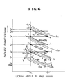
- the reason why the yarn is suitably traversed is that the winding ratio such that the occurrence of the ribbonning is prevented is determined in advance in the program JOB-1 before the operation of the yarn take-up machine commences. The determination of such winding ratio will hereinafter be described in detail in conjunction with FIG. 6.
- the yarn winding speed V1, yarn traverse stroke S, yarn width w, upper limit value ⁇ H of the leash angle, and ribbon occurrence region Y are first inputted at the step P1 of the program JOB-1.
- the lower limit value ⁇ L of the leash angle is then calculated in accordance with the upper limit value ⁇ H of the leash angle inputted at the step P1 and the aforementioned equation (1).
- the number of turns T0 of the yarn wound on the unwound bobbin 2 over one layer (that is, the number of turns T0 of the yarn when a distance of two traverse strokes 2S is divided by the width w of the yarn) is calculated by the aforementioned equation (2) and changed into an integral number.
- the number of turns T 1(0) of the yarn over one pitch (when the diameter D N is equal to D0 and the upper limit value of the leash angle is ⁇ H ) is calculated by the aforementioned equation (3) wherein the change count value N equals to zero, and changed into an integral number.
- the temporary winding ratio M0 is calculated by the aforementioned equation (4) wherein the change count value N equals to zero. That is, a winding ratio of a point a indicated in FIG. 6 is obtained.
- the temporary winding ratio M0 of the point a is compared with the ribbon occurrence region Y.
- the T 1(0) and the T0 are discriminated whether they are prime numbers from each other or not.
- a value of 1 is added to the T0.
- the true winding ratio W0 is calculated in accordance with the aforementioned equation (6) wherein the change count value N equals to zero.
- the winding ratio W0 thus obtained corresponds to a point b indicated in FIG. 6. Accordingly, a point m of FIG. 6 is a starting point of the winding ratio of the unwound bobbin.
- the yarn package diameter D1 is calculated when the lower limit value of the leash angle and the winding ratio are ⁇ L and W0, respectively. That is, the diameter of a point c of FIG. 6 is obtained.
- the yarn package diameter D1 is compared with the unwound bobbin diameter D0 previously calculated. Since the diameter D1 is more than the diameter D0, the winding ratio W0 corresponding to the diameter D0 is memorized. As a result, the yarn is wound between the diameters D0 and D1 with the winding ratio W0 indicated by line m-c which is not within the bobbin occurrence region Y. In this instance, since the diameter D0 is less than the maximum diameter D H of the machine specification value, the program JOB-1 is repeated.
- a new T0 is calculated when the temporary winding ratio is the upper limit value R 2H of the ribbon occurrence region Y, and changed into an integral number.
- the temporary winding ratio R 2H corresponds to a point e indicated in FIG. 6.
- the T 1(1) and the T0 are discriminated whether they are prime numbers from each other or not. Since the T0 and the T 1(1) are prime numbers from each other, the true winding ratio W1 is calculated.
- the diameter D2 is calculated from the winding ratio W1 when the lower limit value of the leash angle is ⁇ L and the winding ratio is W1.
- the diameter D2 corresponds to a point f of FIG. 6.
- the diameter D2 is compared with the diameter D1 previously calculated.
- the winding ratio W1 corresponding to the diameter D1 is memorized.
- the winding ratio W1 starts from a point n of FIG. 6 when the diameter is D1.
- the diameter D1 is compared with the maximum diameter D H of the machine specification value. Since the diameter D1 is still less than the maximum diameter D H of the machine specification value, the program JOB-1 is repeated.
- the change count value N is increased to 2, and the number of turns T 1(2) is first calculated when the diameter of the package is D2 and the upper limit value of the leash angle is ⁇ H , and the winding ratio M2 is calculated this time.
- the winding ratio M2 corresponds to a point g indicated in FIG. 6.
- the above noted processes are hereinafter repeated.
- the winding ratio M2 between the package diameters D2 and D3 is indicated by line g-h.
- the winding ratio M3 between the package diameters D3 and D4 is indicated by line i-j.
- the winding ratio M4 between the package diameters D4 and D5 is indicated by line k-o.
- the package diameter D5 at the point o is compared with with the maximum diameter D H of the machine. In this embodiment, since the package diameter D5 is more than the maximum diameter D H , the program JOB-1 ends.
- the winding ratio which is capable of suitably avoiding the occurrence of the ribbonning is properly set up in advance in accordance with the various datum of yarn. Accordingly, the occurrence of the ribbonning can be effectively prevented when the yarn is traversed in opposite directions in accordance with the program JOB-2.
- FIG. 7 shows a characteristic of winding ratio when the difference between the upper and lower limit values ⁇ H and ⁇ L of the leash angle is small.
- the winding ratio between points a ⁇ and b ⁇ is calculated as in the case of FIG. 6.
- the winding ratio M N of a point c ⁇ is calculated.
- the package diameter D N of a point e ⁇ is calculated.
- the change of the width may be also determined in accordance with the winding ratio W N at the step preceding to the step P13.
- the T0 has been processed when the T0 and T 1(N) are prime numbers from each other, it is noted that the T 1(N) may be processed.
- a desired winding ratio is suitably selected depending upon the yarn width and the like. Accordingly, in the case that a various kinds of brands of different deniers are produced with a short cycle, the winding ratio can be easily varied depending upon different widths of different yarns. As a result, in the present invention, a loss resulting from the change of brands and a cost of production are extremely reduced.
- the yarn traverse apparatus Since the number of rotations of the bobbin is detected without mechanically connecting the bobbin with the yarn traversing device and in accordance with this detected value the number of traverse strokes is calculated, the yarn traverse apparatus according to the present invention does not has the disadvantages that there are fluctuations of winding ratio due to the contact pressure applied between the package and the friction roller and due to the rib portions at the axial opposite ends of the package, and thus the yarn is enhanced in quality.
- the width between the upper and lower limit values ⁇ H and ⁇ L of the leash angle has been maintained constant from the beginning to the end of the winding operation
- the width of the leash angle may also be controlled to be selected between 0.1 and 0.2 degrees if the winding ratio is not within the ribbon occurrence region and minimized only when the winding ratio is within the ribbon occurrence region.
- the step P2 of the program shown in FIG. 3 is omitted and a new step P 4a is added therefor.
- the upper limit value ⁇ H of the leash angle is calculated in accordance with the following equation (10)
- the ratio of the upper and lower limit values ⁇ H and ⁇ L is raised to a unit with M N and R H for the first time, and the upper limit value ⁇ H increases by 0.1 degrees because D N is equal to or less than D N-1 after the second time. Thereafter, the width between the upper and lower limit values ⁇ H and ⁇ L is varied and reduced to the minimum value so that the winding ratio is moved outside the ribbon occurrence region.
- the value of ⁇ L is inputted in stead of the value of ⁇ H .
- the value of 0.2 in the equation (10) may be inputted as an input data at the step P1.
- the yarn winding speed has been detected in the calculation of the package diameter D N
- values set by the setting device may be also used.
- the present invention is applicable to both yarn take-up devices of the spindle drive type and the friction drive type. While, in the first and second embodiments, the induction motor has been used, it is noted that a synchronous motor, a DC motor and the like may be also used.
Landscapes
- Engineering & Computer Science (AREA)
- Textile Engineering (AREA)
- Winding Filamentary Materials (AREA)
Applications Claiming Priority (2)
| Application Number | Priority Date | Filing Date | Title |
|---|---|---|---|
| JP129566/86 | 1986-06-03 | ||
| JP61129566A JPS62290682A (ja) | 1986-06-03 | 1986-06-03 | トラバ−ス装置 |
Publications (3)
| Publication Number | Publication Date |
|---|---|
| EP0248406A2 true EP0248406A2 (fr) | 1987-12-09 |
| EP0248406A3 EP0248406A3 (en) | 1988-11-02 |
| EP0248406B1 EP0248406B1 (fr) | 1992-09-16 |
Family
ID=15012650
Family Applications (1)
| Application Number | Title | Priority Date | Filing Date |
|---|---|---|---|
| EP87107972A Expired EP0248406B1 (fr) | 1986-06-03 | 1987-06-02 | Appareil de va-et-vient pour fil |
Country Status (4)
| Country | Link |
|---|---|
| US (1) | US4771961A (fr) |
| EP (1) | EP0248406B1 (fr) |
| JP (1) | JPS62290682A (fr) |
| DE (1) | DE3781719T2 (fr) |
Cited By (5)
| Publication number | Priority date | Publication date | Assignee | Title |
|---|---|---|---|---|
| EP0375043A1 (fr) * | 1988-12-23 | 1990-06-27 | SAVIO S.p.A. | Procédé pour contrôler l'enroulage du fil dans un dispositif de bobinage de fils synthétiques |
| EP0486896A1 (fr) * | 1990-11-23 | 1992-05-27 | NEUMAG - Neumünstersche Maschinen- und Anlagenbau GmbH | Procédé pour enrouler un fil en enroulement de precision etage |
| EP0538961A1 (fr) * | 1991-10-25 | 1993-04-28 | SAVIO S.p.A. | Procédé pour répartir un fil lors de son enroulement dans un dispositif de bobinage |
| EP0561188A1 (fr) * | 1992-03-16 | 1993-09-22 | Georg Sahm Gmbh & Co. Kg | Procédé pour le bobinage en enroulement croisé de précision d'un matériau en forme de bande ou de fil |
| WO1994011290A1 (fr) * | 1992-11-13 | 1994-05-26 | Maschinenfabrik Rieter Ag | Procede et dispositif de bobinage d'un fil |
Families Citing this family (15)
| Publication number | Priority date | Publication date | Assignee | Title |
|---|---|---|---|---|
| DE3918846A1 (de) * | 1989-06-09 | 1990-12-13 | Maag Fritjof | Praezisionskreuzspule, verfahren zu deren herstellung und spuleinrichtung dafuer |
| IT1251866B (it) * | 1991-09-24 | 1995-05-26 | Fadis Spa | Metodo per il controllo della posizione del punto di inversione del filato particolarmente per macchine roccatrici e relativa apparecchiatura |
| DE4223271C1 (fr) * | 1992-07-17 | 1993-06-24 | Neumag - Neumuenstersche Maschinen- Und Anlagenbau Gmbh, 2350 Neumuenster, De | |
| TW258761B (fr) * | 1993-10-19 | 1995-10-01 | Barmag Barmer Maschf | |
| DE19619706A1 (de) * | 1995-05-29 | 1996-12-05 | Barmag Barmer Maschf | Verfahren zur Erzielung einer Spiegelstörung |
| DE19607905B4 (de) * | 1996-03-01 | 2006-09-14 | Saurer Gmbh & Co. Kg | Verfahren und Vorrichtung zum Herstellen von Kreuzspulen in wilder Wicklung |
| WO1998033735A1 (fr) * | 1997-02-05 | 1998-08-06 | Plant Engineering Consultants, Inc. | Procede et appareil de bobinage de precision |
| TW359661B (en) * | 1997-04-24 | 1999-06-01 | Barmag Barmer Maschf | Method of winding a yarn to cylindrical cross-wound package |
| US6568623B1 (en) * | 2000-03-21 | 2003-05-27 | Owens-Corning Fiberglas Technology, Inc. | Method for controlling wind angle and waywind during strand package buildup |
| JP4711103B2 (ja) * | 2003-03-28 | 2011-06-29 | 村田機械株式会社 | 糸の巻き取り方法とその装置 |
| SI22124A (sl) * | 2006-12-07 | 2007-04-30 | Danilo Jaksic | Metoda precizijskega navijanja tekstilne preje na navitke z veckratnim spreminjanjem navijalnega razmerja znotraj enega ciklusa navijanja |
| DE102008008083A1 (de) | 2008-01-28 | 2009-07-30 | Wilhelm Stahlecker Gmbh | Verfahren und Vorrichtung zum Herstellen von Kreuzwickelspulen |
| US11878892B2 (en) | 2015-09-22 | 2024-01-23 | Infinity Physics, Llc | Linear media handling system and devices produced using the same |
| EP3353794B1 (fr) | 2015-09-22 | 2023-12-06 | Infinity Physics, LLC | Système de manipulation de supports linéaires et dispositifs produits à l'aide de celui-ci |
| US12603563B2 (en) | 2021-01-26 | 2026-04-14 | Electric Mayhem, Llc | Superconducting motors and components thereof |
Family Cites Families (12)
| Publication number | Priority date | Publication date | Assignee | Title |
|---|---|---|---|---|
| CH603469A5 (fr) * | 1975-11-05 | 1978-08-15 | Rieter Ag Maschf | |
| DE2606208C3 (de) * | 1976-02-17 | 1982-12-16 | Bayer Ag, 5090 Leverkusen | Spulverfahren zum Herstellen von Kreuzspulen wilder Wicklung |
| JPS5733264A (en) * | 1980-08-01 | 1982-02-23 | Iseki & Co Ltd | Input shaft bearing retainer in transmission mechanism |
| US4394986A (en) * | 1981-05-13 | 1983-07-26 | Toray Industries, Inc. | Yarn winding apparatus |
| JPS5871053U (ja) * | 1981-11-04 | 1983-05-14 | 帝人株式会社 | 巻取制御装置 |
| JPS5878953A (ja) * | 1981-11-04 | 1983-05-12 | Teijin Ltd | 糸条巻取装置 |
| US4504021A (en) * | 1982-03-20 | 1985-03-12 | Barmag Barmer Maschinenfabrik Ag | Ribbon free wound yarn package and method and apparatus for producing the same |
| DE3368253D1 (en) * | 1982-05-03 | 1987-01-22 | Barmag Barmer Maschf | Method of avoiding images at the random cross winding of a yarn |
| US4504024A (en) * | 1982-05-11 | 1985-03-12 | Barmag Barmer Maschinenfabrik Ag | Method and apparatus for producing ribbon free wound yarn package |
| CH659055A5 (de) * | 1982-09-27 | 1986-12-31 | Schweiter Ag Maschf | Kreuzspulmaschine zum herstellen der wicklung einer kreuzspule. |
| DE3401530A1 (de) * | 1984-01-18 | 1985-07-25 | Fritjof Dipl.-Ing. Dr.-Ing. 6233 Kelkheim Maag | Praezisionsspule, sowie verfahren und vorrichtung zu deren herstellung |
| CN1005029B (zh) * | 1985-03-05 | 1989-08-23 | 巴马格·巴默机器制造股份公司 | 卷绕方法 |
-
1986
- 1986-06-03 JP JP61129566A patent/JPS62290682A/ja active Granted
-
1987
- 1987-06-02 DE DE8787107972T patent/DE3781719T2/de not_active Expired - Fee Related
- 1987-06-02 US US07/056,690 patent/US4771961A/en not_active Expired - Lifetime
- 1987-06-02 EP EP87107972A patent/EP0248406B1/fr not_active Expired
Cited By (9)
| Publication number | Priority date | Publication date | Assignee | Title |
|---|---|---|---|---|
| EP0375043A1 (fr) * | 1988-12-23 | 1990-06-27 | SAVIO S.p.A. | Procédé pour contrôler l'enroulage du fil dans un dispositif de bobinage de fils synthétiques |
| US5056724A (en) * | 1988-12-23 | 1991-10-15 | Savio S.P.A. | Process and apparatus for controlling distribution of thread on a package in a collection unit for synthetic threads |
| EP0486896A1 (fr) * | 1990-11-23 | 1992-05-27 | NEUMAG - Neumünstersche Maschinen- und Anlagenbau GmbH | Procédé pour enrouler un fil en enroulement de precision etage |
| DE4037278A1 (de) * | 1990-11-23 | 1992-05-27 | Neumag Gmbh | Verfahren zum aufspulen eines fadens in gestufter praezisionswicklung |
| EP0538961A1 (fr) * | 1991-10-25 | 1993-04-28 | SAVIO S.p.A. | Procédé pour répartir un fil lors de son enroulement dans un dispositif de bobinage |
| EP0561188A1 (fr) * | 1992-03-16 | 1993-09-22 | Georg Sahm Gmbh & Co. Kg | Procédé pour le bobinage en enroulement croisé de précision d'un matériau en forme de bande ou de fil |
| US5439184A (en) * | 1992-03-16 | 1995-08-08 | Georg Sahm Gmbh & Co. Kg | Precision winding method and apparatus |
| WO1994011290A1 (fr) * | 1992-11-13 | 1994-05-26 | Maschinenfabrik Rieter Ag | Procede et dispositif de bobinage d'un fil |
| US5605295A (en) * | 1992-11-13 | 1997-02-25 | Maschinenfabrik Rieter Ag | Method and device for winding a yarn |
Also Published As
| Publication number | Publication date |
|---|---|
| JPS62290682A (ja) | 1987-12-17 |
| DE3781719D1 (de) | 1992-10-22 |
| US4771961A (en) | 1988-09-20 |
| DE3781719T2 (de) | 1993-04-29 |
| JPH0369822B2 (fr) | 1991-11-05 |
| EP0248406B1 (fr) | 1992-09-16 |
| EP0248406A3 (en) | 1988-11-02 |
Similar Documents
| Publication | Publication Date | Title |
|---|---|---|
| EP0248406B1 (fr) | Appareil de va-et-vient pour fil | |
| US4022391A (en) | Spooling machine system and method to wind multi-layer spools, particularly for wire, tape and the like | |
| EP0375043B1 (fr) | Procédé pour contrôler l'enroulage du fil dans un dispositif de bobinage de fils synthétiques | |
| US4394986A (en) | Yarn winding apparatus | |
| EP0630846B1 (fr) | Procédé, et dispositif de distribution de fil enroulé sur une bobine entraínée par un rouleau rainuré | |
| EP0196090B2 (fr) | Détecteur d'anomalie dans un dispositif de bobinage de fil | |
| US4779813A (en) | Method of winding yarn on bobbin and machine therefor | |
| JP3285405B2 (ja) | ワインダーに導入されるテープ状または糸状の巻体を精密巻を有するチーズ巻にして巻取る方法とその装置 | |
| GB2127443A (en) | Method and traverse winding frame for winding a thread on a bobbin | |
| US4697753A (en) | Stepped precision winding process | |
| EP0470273B1 (fr) | Procédé et dispositif pour bobiner un fil | |
| CN1065507C (zh) | 卷绕机的旋转传动装置的控制方法 | |
| US4485978A (en) | Method and apparatus for winding strand upon spools having tapered end flanges | |
| CN1170690A (zh) | 生产交叉卷绕筒子的方法和装置 | |
| US6523774B2 (en) | Method and apparatus for winding a continuously advancing yarn | |
| CN1082486C (zh) | 筒子的生产方法和装置 | |
| EP0064579B1 (fr) | Bobinoir pour fil textile | |
| JPH06200428A (ja) | ワインダーに導入される糸状の巻取品を段付き精密チーズ巻にして一定速度で連続的に巻き取る方法とこの方法を実行するワインダー | |
| EP0016942B1 (fr) | Machine de bobinage | |
| US4738406A (en) | Control apparatus and method | |
| US6308907B1 (en) | Method for winding up a thread | |
| USRE33240E (en) | Control apparatus and method | |
| EP0630845A1 (fr) | Procédé et dispositif de distribution de fil enroulé sur une bobine au moyen d'un rouleau d'entraînement et un guide-fil | |
| JPH07256338A (ja) | 線条体用リール巻取機のトラバース制御装置 | |
| JP2694736B2 (ja) | 糸条の巻取機 |
Legal Events
| Date | Code | Title | Description |
|---|---|---|---|
| PUAI | Public reference made under article 153(3) epc to a published international application that has entered the european phase |
Free format text: ORIGINAL CODE: 0009012 |
|
| AK | Designated contracting states |
Kind code of ref document: A2 Designated state(s): CH DE IT LI |
|
| PUAL | Search report despatched |
Free format text: ORIGINAL CODE: 0009013 |
|
| AK | Designated contracting states |
Kind code of ref document: A3 Designated state(s): CH DE IT LI |
|
| 17P | Request for examination filed |
Effective date: 19881223 |
|
| 17Q | First examination report despatched |
Effective date: 19900711 |
|
| ITTA | It: last paid annual fee | ||
| GRAA | (expected) grant |
Free format text: ORIGINAL CODE: 0009210 |
|
| AK | Designated contracting states |
Kind code of ref document: B1 Designated state(s): CH DE IT LI |
|
| REF | Corresponds to: |
Ref document number: 3781719 Country of ref document: DE Date of ref document: 19921022 |
|
| ITF | It: translation for a ep patent filed | ||
| PLBE | No opposition filed within time limit |
Free format text: ORIGINAL CODE: 0009261 |
|
| STAA | Information on the status of an ep patent application or granted ep patent |
Free format text: STATUS: NO OPPOSITION FILED WITHIN TIME LIMIT |
|
| 26N | No opposition filed | ||
| PGFP | Annual fee paid to national office [announced via postgrant information from national office to epo] |
Ref country code: CH Payment date: 20010529 Year of fee payment: 15 |
|
| PGFP | Annual fee paid to national office [announced via postgrant information from national office to epo] |
Ref country code: DE Payment date: 20020610 Year of fee payment: 16 |
|
| PG25 | Lapsed in a contracting state [announced via postgrant information from national office to epo] |
Ref country code: LI Free format text: LAPSE BECAUSE OF NON-PAYMENT OF DUE FEES Effective date: 20020630 Ref country code: CH Free format text: LAPSE BECAUSE OF NON-PAYMENT OF DUE FEES Effective date: 20020630 |
|
| REG | Reference to a national code |
Ref country code: CH Ref legal event code: PL |
|
| PG25 | Lapsed in a contracting state [announced via postgrant information from national office to epo] |
Ref country code: DE Free format text: LAPSE BECAUSE OF NON-PAYMENT OF DUE FEES Effective date: 20040101 |
|
| PG25 | Lapsed in a contracting state [announced via postgrant information from national office to epo] |
Ref country code: IT Free format text: LAPSE BECAUSE OF NON-PAYMENT OF DUE FEES Effective date: 20050602 |