EP0248417B1 - Cathode imprégnée - Google Patents
Cathode imprégnée Download PDFInfo
- Publication number
- EP0248417B1 EP0248417B1 EP87108036A EP87108036A EP0248417B1 EP 0248417 B1 EP0248417 B1 EP 0248417B1 EP 87108036 A EP87108036 A EP 87108036A EP 87108036 A EP87108036 A EP 87108036A EP 0248417 B1 EP0248417 B1 EP 0248417B1
- Authority
- EP
- European Patent Office
- Prior art keywords
- phase
- cathode
- εii
- layer
- impregnated
- Prior art date
- Legal status (The legal status is an assumption and is not a legal conclusion. Google has not performed a legal analysis and makes no representation as to the accuracy of the status listed.)
- Expired
Links
- 238000010438 heat treatment Methods 0.000 claims description 24
- 229910045601 alloy Inorganic materials 0.000 claims description 22
- 239000000956 alloy Substances 0.000 claims description 22
- 239000008188 pellet Substances 0.000 claims description 18
- 229910052741 iridium Inorganic materials 0.000 claims description 14
- 229910052721 tungsten Inorganic materials 0.000 claims description 13
- GKOZUEZYRPOHIO-UHFFFAOYSA-N iridium atom Chemical compound [Ir] GKOZUEZYRPOHIO-UHFFFAOYSA-N 0.000 claims description 12
- 238000000034 method Methods 0.000 claims description 12
- WFKWXMTUELFFGS-UHFFFAOYSA-N tungsten Chemical compound [W] WFKWXMTUELFFGS-UHFFFAOYSA-N 0.000 claims description 11
- 239000010937 tungsten Substances 0.000 claims description 11
- 239000013078 crystal Substances 0.000 claims description 6
- 229910052784 alkaline earth metal Inorganic materials 0.000 claims description 3
- 238000004519 manufacturing process Methods 0.000 claims description 2
- 239000010410 layer Substances 0.000 description 26
- 230000032683 aging Effects 0.000 description 16
- 239000011247 coating layer Substances 0.000 description 13
- 238000002441 X-ray diffraction Methods 0.000 description 5
- 239000002345 surface coating layer Substances 0.000 description 5
- 238000005275 alloying Methods 0.000 description 4
- QVQLCTNNEUAWMS-UHFFFAOYSA-N barium oxide Chemical compound [Ba]=O QVQLCTNNEUAWMS-UHFFFAOYSA-N 0.000 description 4
- 239000000203 mixture Substances 0.000 description 4
- 238000004544 sputter deposition Methods 0.000 description 4
- 230000003247 decreasing effect Effects 0.000 description 3
- 239000000463 material Substances 0.000 description 3
- 229910001080 W alloy Inorganic materials 0.000 description 2
- 230000015572 biosynthetic process Effects 0.000 description 2
- BRPQOXSCLDDYGP-UHFFFAOYSA-N calcium oxide Chemical compound [O-2].[Ca+2] BRPQOXSCLDDYGP-UHFFFAOYSA-N 0.000 description 2
- ODINCKMPIJJUCX-UHFFFAOYSA-N calcium oxide Inorganic materials [Ca]=O ODINCKMPIJJUCX-UHFFFAOYSA-N 0.000 description 2
- 239000000292 calcium oxide Substances 0.000 description 2
- 238000001704 evaporation Methods 0.000 description 2
- TWNQGVIAIRXVLR-UHFFFAOYSA-N oxo(oxoalumanyloxy)alumane Chemical compound O=[Al]O[Al]=O TWNQGVIAIRXVLR-UHFFFAOYSA-N 0.000 description 2
- 239000002344 surface layer Substances 0.000 description 2
- 229910052715 tantalum Inorganic materials 0.000 description 2
- GUVRBAGPIYLISA-UHFFFAOYSA-N tantalum atom Chemical compound [Ta] GUVRBAGPIYLISA-UHFFFAOYSA-N 0.000 description 2
- 230000007704 transition Effects 0.000 description 2
- KJTLSVCANCCWHF-UHFFFAOYSA-N Ruthenium Chemical compound [Ru] KJTLSVCANCCWHF-UHFFFAOYSA-N 0.000 description 1
- 229910000905 alloy phase Inorganic materials 0.000 description 1
- 239000011248 coating agent Substances 0.000 description 1
- 238000000576 coating method Methods 0.000 description 1
- 238000007872 degassing Methods 0.000 description 1
- 230000000593 degrading effect Effects 0.000 description 1
- 230000008020 evaporation Effects 0.000 description 1
- 230000001747 exhibiting effect Effects 0.000 description 1
- 238000002474 experimental method Methods 0.000 description 1
- 230000004927 fusion Effects 0.000 description 1
- 239000011521 glass Substances 0.000 description 1
- 238000011065 in-situ storage Methods 0.000 description 1
- 229910000765 intermetallic Inorganic materials 0.000 description 1
- 238000005259 measurement Methods 0.000 description 1
- 229910052751 metal Inorganic materials 0.000 description 1
- 239000002184 metal Substances 0.000 description 1
- 230000003287 optical effect Effects 0.000 description 1
- 229910052762 osmium Inorganic materials 0.000 description 1
- SYQBFIAQOQZEGI-UHFFFAOYSA-N osmium atom Chemical compound [Os] SYQBFIAQOQZEGI-UHFFFAOYSA-N 0.000 description 1
- BASFCYQUMIYNBI-UHFFFAOYSA-N platinum Chemical group [Pt] BASFCYQUMIYNBI-UHFFFAOYSA-N 0.000 description 1
- 239000011148 porous material Substances 0.000 description 1
- WUAPFZMCVAUBPE-UHFFFAOYSA-N rhenium atom Chemical compound [Re] WUAPFZMCVAUBPE-UHFFFAOYSA-N 0.000 description 1
- 229910052707 ruthenium Inorganic materials 0.000 description 1
- 229920006395 saturated elastomer Polymers 0.000 description 1
Images



Classifications
-
- H—ELECTRICITY
- H01—ELECTRIC ELEMENTS
- H01J—ELECTRIC DISCHARGE TUBES OR DISCHARGE LAMPS
- H01J1/00—Details of electrodes, of magnetic control means, of screens, or of the mounting or spacing thereof, common to two or more basic types of discharge tubes or lamps
- H01J1/02—Main electrodes
- H01J1/13—Solid thermionic cathodes
- H01J1/20—Cathodes heated indirectly by an electric current; Cathodes heated by electron or ion bombardment
- H01J1/28—Dispenser-type cathodes, e.g. L-cathode
Definitions
- the present invention relates to an impregnated cathode used in an electron tube or the like and, more particularly, to a surface coating layer thereof, used for thermionic emission.
- An impregnated cathode is obtained by impregnating pores of a porous pellet with an electron-emission material such as barium oxide, calcium oxide, aluminum oxide, etc.
- an electron-emission material such as barium oxide, calcium oxide, aluminum oxide, etc.
- Such a cathode can provide a current density higher than a conventional oxide thermal cathode, and has a longer service life, since it is resistant to a harmful gas, contained in a tube, and which interferes with electron emission. Consequently, cathodes of this type are employed in a travelling-wave tube used in, for example, artificial satellites, in a high-power klystron used for plasma heating in a nuclear fusion reactor, etc.
- Such devices have been described in e.g. EP-A-0 156 454 and EP-A-0 157 634.
- a layer of an element of the platinum group such as iridium, osmium, ruthenium, etc. or an alloy thereof, is coated on the cathode surface, in order to decrease the work function of the cathode surface, thereby to decrease the operating temperature.
- the operating temperature of a cathode having a coating layer can be decreased by several tens to one hundred and several tens °C, to obtain the same current density. Since evaporation of the electron emission material can then be limited, this is advantageous for a cathode, with regard to prolongation of its service life, and provides an improvement in the intratube withstand voltage characteristics.
- the operating temperature in this case is still as high as 900 to 1,000°C. Therefore, W for forming a pellet is diffused in the surface coating layer during operation, and forms an alloy together with a metal constituting the surface coating layer. Alloying of the surface coating layer changes the electron-emission characteristics, and interferes with the achieving of stable characteristics from an early stage of operation, and with the prolongation of the service life.
- the present invention has as its object to provide an impregnated cathode which maintains stable electron emission characteristics from the early stage of operation, and a method of manufacturing the same.
- the present invention provides an impregnated cathode wherein an alloy layer of iridium and tungsten is formed on a surface of a porous pellet impregnated with an oxide of an alkali earth metal, wherein the crystal structure of the alloy has an ⁇ II phase comprising an hcp (hexagonal close-packed) structure whose lattice constants a and c satisfy 2.76 x 10 ⁇ 10m ⁇ a ⁇ 2.78 x 10 ⁇ 10m and 4.44 x 10 ⁇ 10m ⁇ c ⁇ 4.46 x 10 ⁇ 10m.
- a layer of iridium is coated on the surface of the porous pellet. Then, the porous pellet is heated in a vacuum or inert atmosphere at 1,100 to 1,260°C, for a predetermined period of time.
- the heating process of the present invention is considerably practical, since it has a good reproducibility.
- the appropriate thickness of the Ir coating layer is 50 x 10 ⁇ 10m to 10,000 x 10 ⁇ 10m ( ⁇ ), because of the ease in controlling the heating time, and in order to preserve the electron emission characteristics of the pellet.
- the thickness of the alloy layer is about twice that of the Ir coating layer, as will be described later. However, when the alloy layer is thinner than 100 x 10 ⁇ 10m ( ⁇ ), the service life of the cathode is decreased; when it is thicker than 20,000 x 10 ⁇ 10m ( ⁇ ), it is necessary for the operating temperature to remain high.
- the heating time in this case is arbitrarily determined within the range of 1 to 360 minutes. If the heating temperature is higher than 1,260°C, the amount of electron emission material evaporating from the pellet is excessive, thereby degrading electron emission characteristics. When the heating temperature is 1,100°C or lower, an extended period of time is required for alloying of the ⁇ II phase; therefore, this is impractical.
- an alloy layer of ⁇ II phase of iridium and tungsten can be used as the coating layer, in place of the iridium layer.
- ⁇ phase of the inter-metallic compound of Ir and W appears after the lighting process (IV).
- the ⁇ phase has an hcp structure.
- a series of diffraction peaks exhibiting the same crystal type appeared on the low-angle sides of the respective diffraction peaks of ⁇ phase.
- the ⁇ phase which appeared in the lighting process will be referred to as ⁇ I phase and the phase that appeared in the aging process will be referred to as ⁇ II phase.
- the discrete changes in the diffraction pattern from ⁇ I to ⁇ II phase correspond to the discrete changes in the lattice constants a and c .
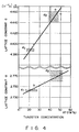
- 2.735 x 10 ⁇ 10m ⁇ a ⁇ 2.745 x 10 ⁇ 10m ( ⁇ ) and 4.385 x 10 ⁇ 10m ⁇ c ⁇ 4.395 x 10 ⁇ 10m ( ⁇ ) were obtained in ⁇ I phase
- 2.760 x 10 ⁇ 10m ⁇ a ⁇ 2.780 x 10 ⁇ 10m ( ⁇ ) and 4.440 x 10 ⁇ 10m ⁇ c ⁇ 4.460 x 10 ⁇ 10m ( ⁇ ) were obtained in ⁇ II phase.
- compositions of the alloy layers after the lighting and aging processes were analyzed by sputtering from the surface in the direction of depth (indicated by a corresponding sputtering time) with an Auger electron spectroscope, and the results shown in Figs. 5A and 5B were obtained.
- Figs. 5A and 5B show relative concentration profiles after lighting and aging processes, respectively.
- Curves 51 and 53 indicate relative iridium concentrations
- curves 52 and 54 indicate relative tungsten concentrations. It is seen that, in the alloy layer after completion of the lighting process, tungsten was quickly diffused in iridium since the tungsten concentration gradient near the surface was small. The tungsten concentration near the surface was about 25 atom %. In the alloy layer after completion of the aging process, the tungsten concentration in the surface and in the layer is 40 to 50 atom %.
- Fig. 6 shows the results obtained by X-ray diffraction.
- the X-ray diffraction intensity ratios plotted along the axis of ordinate are ratios of the ⁇ II phase diffraction peak intensities to the sum of the diffraction peak intensities of Ir layer, ⁇ I and ⁇ II phases.
- Curves 61, 62, 63, and 64 indicate ratios when the thicknesses of the iridium coating layers are 1,000, 2,000, 3,500, and 5,000 x 10 ⁇ 10m ( ⁇ ), respectively.
- the heating temperature was 1,180°C.
- the aging time required for the transition from ⁇ I to ⁇ II phase depends on the thickness of the Ir coating layer and that the thicker the Ir layer, the longer the ⁇ II phase formation time. Therefore, when the aging time is set constant, in order to form a perfect ⁇ II phase, the thicker the Ir coating layer, the higher the heating temperature.
- Fig. 7 shows a change in the maximum emission value in a space charge limiting region, i.e., MISC (Maximum I k Saturated Current) with respect to the aging time for each Ir layer thickness.
- Curves 71, 72, 73, and 74 indicate MISC's when the thicknesses of the Ir coating layers are 1,000, 2,000, 3,500, and 5,000 x 10 ⁇ 10m ( ⁇ ), respectively.
- An MISC is a value measured 1 second after the start of an anode voltage application. It is seen from these results that the thicker the Ir coating layer, the less the increase in MISC, and that a longer heating time is required to activate emission.
- the electron emission characteristics of MISC were measured in a plane-parallel diode glass dummy tube. During measurement of the electron emission characteristics, the cathode temperature was decreased to 1,000°C so that aging did not proceed.
- Fig. 8 shows its result. It is seen in Fig. 8 that the thickness of the alloy layer formed is about twice that of the thickness of the Ir layer before the heating process.
- a mixture of barium oxide, calcium oxide, and aluminum oxide (in a molar ratio of about 4 : 1 : 1) was melted and impregnated in a porous tungsten pellet having a diameter of 1.5 mm, a thickness of 0.4 mm, and a porosity of about 20%.
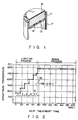
- the surface of the pellet was cleaned to remove excessive Ba, thereby forming impregnated pellet 11 shown in Fig. 1.
- pellet 11 was welded to tantalum cup 13 having a thickness of 25 ⁇ m through rhenium wire 15. Cup 13 was welded to an opening at one end of tantalum support sleeve 17.
- Sleeve 17 was fixed to a support cylinder (not shown) through three support straps of a rheniummolybdenum alloy, thereby forming a cathode.
- An Ir layer having a thickness of 3,500 x 10 ⁇ 10m ( ⁇ ) was formed by sputtering on the surface of pellet 11.
- the cathode was placed in a vacuum bell jar evacuated to 133.32 x 10 ⁇ 7 Pa (Torr) or less.
- a heater (not shown) was powered to heat the cathode at a predetermined temperature for a predetermined period of time.
- Fig. 2 shows the time and temperature in this heating process.
- the heating process consists of a lighting process (I, II, III,IV, V, and VI) for gradually heating the cathode for the purpose of degassing, and an aging process (VII, VIII, and IX) for heating the cathode at a constant temperature of a brightness temperature of about 1,180°C for a predetermined period of time.
- the brightness temperature was that of the cathode surface measured with a optical eyrometer with 650 nm filter.
- This impregnated cathode was incorporated in a travelling-wave tube for an artificial satellite and was started. Electron emission characteristics having a considerably excellent stability were obtained even after a lapse of a long time from the initial stage of operation.
- Samples obtained by coating Ir layers to thicknesses of 50 to 10,000 x 10 ⁇ 10m ( ⁇ ) on the surfaces of porous pellets by sputtering were prepared and were subjected to predetermined heating.
- This surface alloying treatment was practiced by two methods; an inside-the-tube heating method to assemble a cathode in an electron tube, that uses this cathode, and energize the heater in the cathode; and a single body heating method to heat the cathode in a vacuum bell jar before assembly in an election tube.
- the inside-the-tube heating method is suitable for a comparatively low-voltage electron tube or the like
- the single body heating method is suitable for a large or high-voltage electron tube or the like.
- a cathode shown in Fig. 1 was formed by using each of these samples, and the following tests were conducted.
- a change in electron-emitting current value was measured at an operating temperature of 1,000°C and under an anode voltage wherein the initial emitting current density was 0.8 A/cm2 in the space charge limiting region.
- the ratios of the electron-emitting current values immediately after the start of operation and 3,000 hours after the start to the electron-emitting current value 100 hours after the start of the operation test were respectively evaluated as the initial and service life characteristics.
- Table 1 shows the result.
- Reference symbols x, ⁇ , o, and o indicate the cases wherein the above ratios were 59% or less, 60 to 79%, 80 to 89%, and 90 to 100%, respectively. The closer to 100%, the more superior the electron-emitting characteristics.
- cathodes in which the ⁇ II phase was observed substantially in the entire portions of their alloy layers are grouped as Examples, and cathodes in which the ⁇ I phase only or both the ⁇ I and ⁇ II phases were observed in their alloy layers are grouped as Controls.
Landscapes
- Solid Thermionic Cathode (AREA)
Claims (4)
- Cathode imprégnée dans laquelle une couche d'alliage (19) d'iridium et de tungstène est placée sur une surface d'une pastille de tungstène poreuse(11) imprégnée d'un oxyde de métal alcalino-terreux, caractérisée en ce que la structure cristalline de l'alliage (phase εII) présente une structure hcp dont les constantes de réseau a et c satisfont respectivement 2,76 x 10⁻¹⁰ m ≦ a ≦ 2,78 x 10⁻¹⁰ m et 4,44 x 10⁻¹⁰ m ≦ c ≦ 4,46 x 10⁻¹⁰ m.
- Cathode imprégnée selon la revendication 1, caractérisée en ce que l'épaisseur de la couche d'alliage (19) est comprise entre 100 x 10⁻¹⁰ m et 20 000 x 10⁻¹⁰m.
- Procédé pour fabriquer une cathode imprégnée dans lequel une couche d'alliage (19) ayant une structure cristalline (phase εII) qui comprend une structure hcp dont les constantes de réseau a et c satisfont respectivement 2,76 x 10⁻¹⁰ m ≦ a ≦ 2,78 x 10⁻¹⁰m et 4,44 x 10⁻¹⁰ m ≦ c ≦ 4,46 x 10⁻¹⁰ m, est formée sur une surface d'une pastille poreuse (11) imprégnée d'un oxyde de métal alcalino-terreux, caractérisé en ce qu'une couche d'iridium ou une couche d'alliage (19) d'iridium et de tungstène est déposée sur la surface de la pastille poreuse (11), et l'ensemble résultant est ensuite chauffé sous vide ou dans une atmosphère inerte entre 1100 et 1260°C.
- Procédé selon la revendication 3, caractérisé en ce que le temps de chauffage est compris entre 1 et 360 minutes.
Applications Claiming Priority (4)
| Application Number | Priority Date | Filing Date | Title |
|---|---|---|---|
| JP61130224A JPH0795422B2 (ja) | 1986-06-06 | 1986-06-06 | 含浸形陰極の製造方法 |
| JP130224/86 | 1986-06-06 | ||
| JP130223/86 | 1986-06-06 | ||
| JP13022386A JPH0782807B2 (ja) | 1986-06-06 | 1986-06-06 | 含浸形陰極構体 |
Publications (3)
| Publication Number | Publication Date |
|---|---|
| EP0248417A2 EP0248417A2 (fr) | 1987-12-09 |
| EP0248417A3 EP0248417A3 (en) | 1989-10-25 |
| EP0248417B1 true EP0248417B1 (fr) | 1992-11-11 |
Family
ID=26465419
Family Applications (1)
| Application Number | Title | Priority Date | Filing Date |
|---|---|---|---|
| EP87108036A Expired EP0248417B1 (fr) | 1986-06-06 | 1987-06-03 | Cathode imprégnée |
Country Status (3)
| Country | Link |
|---|---|
| US (1) | US4928034A (fr) |
| EP (1) | EP0248417B1 (fr) |
| DE (1) | DE3782543T2 (fr) |
Families Citing this family (3)
| Publication number | Priority date | Publication date | Assignee | Title |
|---|---|---|---|---|
| US4986788A (en) * | 1989-11-02 | 1991-01-22 | Samsung Electron Devices Co., Ltd. | Process of forming an impregnated cathode |
| KR920004900B1 (ko) * | 1990-03-13 | 1992-06-22 | 삼성전관 주식회사 | 함침형 음극구조체와 그 제조방법 |
| DE19527723A1 (de) * | 1995-07-31 | 1997-02-06 | Philips Patentverwaltung | Elektrische Entladungsröhre oder Entladungslampe und Scandat-Vorratskathode |
Family Cites Families (8)
| Publication number | Priority date | Publication date | Assignee | Title |
|---|---|---|---|---|
| US4165473A (en) * | 1976-06-21 | 1979-08-21 | Varian Associates, Inc. | Electron tube with dispenser cathode |
| JPS5471550A (en) * | 1977-11-18 | 1979-06-08 | Hitachi Ltd | Base metal material for direct heating oxide cathode |
| US4417173A (en) * | 1980-12-09 | 1983-11-22 | E M I-Varian Limited | Thermionic electron emitters and methods of making them |
| JPS58154131A (ja) * | 1982-03-10 | 1983-09-13 | Hitachi Ltd | 含浸形陰極 |
| JPS6068527A (ja) * | 1983-09-26 | 1985-04-19 | Toshiba Corp | 含浸型陰極 |
| JPS60138822A (ja) * | 1983-12-27 | 1985-07-23 | Hitachi Ltd | 含浸形陰極 |
| EP0156454B1 (fr) * | 1984-02-24 | 1987-12-09 | Thorn Emi-Varian Limited | Source d'électrons à émission thermo-ionique |
| US4675570A (en) * | 1984-04-02 | 1987-06-23 | Varian Associates, Inc. | Tungsten-iridium impregnated cathode |
-
1987
- 1987-06-03 DE DE8787108036T patent/DE3782543T2/de not_active Expired - Lifetime
- 1987-06-03 EP EP87108036A patent/EP0248417B1/fr not_active Expired
-
1988
- 1988-11-18 US US07/273,157 patent/US4928034A/en not_active Expired - Lifetime
Also Published As
| Publication number | Publication date |
|---|---|
| DE3782543D1 (de) | 1992-12-17 |
| EP0248417A2 (fr) | 1987-12-09 |
| US4928034A (en) | 1990-05-22 |
| EP0248417A3 (en) | 1989-10-25 |
| DE3782543T2 (de) | 1993-05-06 |
Similar Documents
| Publication | Publication Date | Title |
|---|---|---|
| US5728435A (en) | Method for enhancing electron emission from carbon-containing cathode | |
| US5089292A (en) | Field emission cathode array coated with electron work function reducing material, and method | |
| US4855637A (en) | Oxidation resistant impregnated cathode | |
| EP0248417B1 (fr) | Cathode imprégnée | |
| US5580291A (en) | Method for manufacturing a glow cathode for an electron tube | |
| US4260665A (en) | Electron tube cathode and method for producing the same | |
| EP0390269B1 (fr) | Cathode à scandate | |
| EP0428206A1 (fr) | Cathode à scandate | |
| EP0263483B2 (fr) | Cathode chaude en forme de fil | |
| KR100291903B1 (ko) | 전자관용산화물음극 | |
| EP1150334B1 (fr) | Electrode pour tube a decharge et tube a decharge l'utilisant | |
| US6600257B2 (en) | Cathode ray tube comprising a doped oxide cathode | |
| JPH0795422B2 (ja) | 含浸形陰極の製造方法 | |
| CN1050438C (zh) | 阴极射线管的浸渍型阴极 | |
| US5239229A (en) | Glow discharge lamp with auxiliary electrode for mounting getter thereon | |
| US5977699A (en) | Cathode for electron tube | |
| KR900003178B1 (ko) | 함침형 음극 구조체 및 그 제조방법 | |
| Sakurai et al. | An improved dispenser cathode | |
| Kimura et al. | Emission characteristics of dispenser cathodes with a fine-grained tungsten top layer | |
| Bachmor | Lifetime experience with low temperature cathodes equipped in super power klystrons | |
| KR100198572B1 (ko) | 함침형 음극의 활성화 처리방법 | |
| KR960003589Y1 (ko) | 함침형 음극 | |
| JP3322465B2 (ja) | 陰極構体及びその製造方法 | |
| KR920008786B1 (ko) | 산화물 음극 | |
| KR100249208B1 (ko) | 함침형 음극 |
Legal Events
| Date | Code | Title | Description |
|---|---|---|---|
| PUAI | Public reference made under article 153(3) epc to a published international application that has entered the european phase |
Free format text: ORIGINAL CODE: 0009012 |
|
| 17P | Request for examination filed |
Effective date: 19870630 |
|
| AK | Designated contracting states |
Kind code of ref document: A2 Designated state(s): DE FR GB |
|
| PUAL | Search report despatched |
Free format text: ORIGINAL CODE: 0009013 |
|
| AK | Designated contracting states |
Kind code of ref document: A3 Designated state(s): DE FR GB |
|
| 17Q | First examination report despatched |
Effective date: 19911227 |
|
| GRAA | (expected) grant |
Free format text: ORIGINAL CODE: 0009210 |
|
| AK | Designated contracting states |
Kind code of ref document: B1 Designated state(s): DE FR GB |
|
| REF | Corresponds to: |
Ref document number: 3782543 Country of ref document: DE Date of ref document: 19921217 |
|
| ET | Fr: translation filed | ||
| PLBE | No opposition filed within time limit |
Free format text: ORIGINAL CODE: 0009261 |
|
| STAA | Information on the status of an ep patent application or granted ep patent |
Free format text: STATUS: NO OPPOSITION FILED WITHIN TIME LIMIT |
|
| 26N | No opposition filed | ||
| REG | Reference to a national code |
Ref country code: GB Ref legal event code: 746 Effective date: 19981010 |
|
| REG | Reference to a national code |
Ref country code: FR Ref legal event code: D6 |
|
| REG | Reference to a national code |
Ref country code: GB Ref legal event code: IF02 |
|
| PGFP | Annual fee paid to national office [announced via postgrant information from national office to epo] |
Ref country code: GB Payment date: 20060531 Year of fee payment: 20 |
|
| PGFP | Annual fee paid to national office [announced via postgrant information from national office to epo] |
Ref country code: DE Payment date: 20060601 Year of fee payment: 20 |
|
| PGFP | Annual fee paid to national office [announced via postgrant information from national office to epo] |
Ref country code: FR Payment date: 20060608 Year of fee payment: 20 |
|
| REG | Reference to a national code |
Ref country code: GB Ref legal event code: PE20 |
|
| PG25 | Lapsed in a contracting state [announced via postgrant information from national office to epo] |
Ref country code: GB Free format text: LAPSE BECAUSE OF EXPIRATION OF PROTECTION Effective date: 20070602 |