EP0248571A2 - Montage de serrure à loquet - Google Patents
Montage de serrure à loquet Download PDFInfo
- Publication number
- EP0248571A2 EP0248571A2 EP87304566A EP87304566A EP0248571A2 EP 0248571 A2 EP0248571 A2 EP 0248571A2 EP 87304566 A EP87304566 A EP 87304566A EP 87304566 A EP87304566 A EP 87304566A EP 0248571 A2 EP0248571 A2 EP 0248571A2
- Authority
- EP
- European Patent Office
- Prior art keywords
- latch
- bolt
- lever
- abutment member
- slide
- Prior art date
- Legal status (The legal status is an assumption and is not a legal conclusion. Google has not performed a legal analysis and makes no representation as to the accuracy of the status listed.)
- Withdrawn
Links
Images

Classifications
-
- E—FIXED CONSTRUCTIONS
- E05—LOCKS; KEYS; WINDOW OR DOOR FITTINGS; SAFES
- E05B—LOCKS; ACCESSORIES THEREFOR; HANDCUFFS
- E05B63/00—Locks or fastenings with special structural characteristics
- E05B63/04—Locks or fastenings with special structural characteristics for alternative use on the right-hand or left-hand side of wings
- E05B63/044—Locks or fastenings with special structural characteristics for alternative use on the right-hand or left-hand side of wings with reversible bolt or bolt head
Definitions
- This invention is concerned with a latch assembly comprising a housing, a latch-bolt slidable in the housing between a projecting position and a retracted position, said latch-bolt having an inclined face and a straight face meeting at an outward edge of the latch-bolt for engagement with a co-operating striker plate, spring means for urging the latch-bolt into its projecting position, and means for effecting retracting movement of the latch-bolt against the action of the spring means, said means comprising a lever which is engageable with an abutment member connected to the latch bolt and which is mounted for pivotal movement between first and second positions corresponding respectively with the projecting and retracted positions of the latch-bolt, the first position of the lever, and thus the projecting position of the latch-bolt, being determined by engagement of the lever with a stop, wherein the stop can be rendered ineffective to determine the projecting position of the latch-bolt and the latter is then movable beyond its projecting position into an extended position in which it is disposed wholly outside the
- latch assemblies are provided having this feature of being accommodatable to left- or right-opening doors, it has been necessary to ensure that the latch assembly is correctly set prior to insertion into the door (or alternatively it would be necessary to remove the lock from the door in order to rotate the latch-bolt), or in other cases it is necessary to provided access to the inside of the housing while the lock is in situ in order to release the latch-bolt for rotation.
- the latch assembly in accordance with the present invention merely by the application of pressure to the latch-bolt when in its retracted position, it can be released from operative engagement with the lever and can thus move to its extended position, in which it can be oriented by rotation, according to the hand of door in which it is mounted.
- This is of course of benefit in the building industry in that in this manner locks can be pre-assembled in doors without any need for ensuring that the latch-bolt is correctly oriented to the way in which the door will be hung, and further of course there is no restraint in hanging a door for left or right opening because of the orientation of the latch-bolt.
- using the latch assembly in accordance with the present invention is of significant value not only in itself, but also with regard to its use in the building industry.
- the latch-bolt is supported by a slide which is mounted for sliding movement in the housing, a rearward position of the slide, and thus the retracted position of the latch-bolt, is determined by a further stop member, which prevents movement of the slide beyond such position in a direction away from its projecting position, and in that the abutment member is mounted on the slide such that the application of pressure to the latch-bolt causes tipping movement of the abutment member to take place thus to move it out of operative engagement with the lever.
- the lever has a first surface portion, which engages with the abutment member during movement between the projecting and retracted positions of the latch-bolt (thus providing the operative engagement therebetween), and a second surface portion on to which the abutment member is urged when moved out of operative engagement with the lever as aforesaid.
- the slide comprises a stop surface which engages the lever when the abutment member is moved out of operative engagement therewith, said stop surface being so positioned in relation to the abutment member that the latter is retained in contact with said second surface portion of the lever.
- the lever is shaped appropriately to its normal operation but, in co-operation with the slide and abutment member, also lends itself to facilitating the movement of the latch-bolt to its extended position.
- the arrangement of the slide with the abutment member thereon provides for the releasable connection between the latch-bolt and the lever, while enabling control of the sliding movement to be maintained through the lever at all times.
- the latch-bolt comprises a head portion, having said inclined face and straight face meeting at its outward edge, and a support rod portion rotatably supported by the slide.
- the head portion thereof is freely rotatable in the slide.
- additional spring means is provided whereby the lever is urged in a direction towards the stop. In this way, the lever is held against the stop during the retracting movement of the latch-bolt, thereby ensuring the the abutment member will ride up the inclined surface of the lever and return to its position of engagement therewith.
- the lever has a follower associated therewith, whereby a handle can be operatively connected with the lever for operating it.
- the handle is used not only for normal operation of the latch-bolt, but also to effect its release to its extended position.
- the latch assembly may be incorporated in a lever lock wherein one of the levers of the lock comprises an extension through which, upon turning the key in an unlocking direction, the latch-bolt is retracted.
- said extension operatively engages the slide of the latch assembly and the lever with the extension is movable in the housing so as not to restrict the movement of the latch-bolt between its retracted and extended positions.
- lever lock incorporating a latch assembly in accordance with the present invention. It will be appreciated that this lever lock has been selected for description merely by way of non-limiting example of the invention.
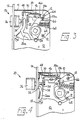
- the lever lock now to be described comprises a housing 10 which is in two parts secured together by screws 12, and one of which parts incorporates a front plate 14 having two apertures 16, 18 through which respectively a latch-bolt 20 and a lock-bolt 22 can pass.
- the lever lock also comprises a lever mechanism generally designated 24 of conventional design, including one lever 26 having an extension 26 a for operating the latch assembly, as will now be described.
- the latch assembly in accordance with the present invention comprises a slide 30 mounted for sliding movement in the housing 10 and comprising a plate having two upstanding wall portions 32 between which is accommodated an end portion of the extension 26 a of the lever 26 of the lever mechanism. Also held captive by said wall portions 32 is a support rod 34 forming part of the latch-bolt 20, the support rod 34 carrying a head portion 36 of the latch-bolt 20, which head portion has an inclined face and a straight face meeting at an outward edge thereof.
- the support rod 34 is mounted in said wall portions 32 for free rotation therein and also for lengthwise sliding movement, the latter being restricted by a collar 38 formed beneath the head portion 36 and a circlip 40 at the end of the rod remote from the head portion. (It will be appreciated that other ways of securing the support rod 34 captive in the slide but free to rotate therein may also be contemplated within the scope of the present invention.)
- the slide 30, and thus the latch-bolt 20, is urged to the left (viewing the drawings), into a position in which the head portion 36 of the latch-bolt is projecting, by means of a torsion spring 42 secured on a boss 44 formed on one of the parts of the housing 10 for receiving a screw 12.
- an abutment member 46 comprising a length of metal strip bent to a generally inverted U-shape.
- a forward, longer, "leg" 46 a of the abutment member has its end cut away so as to be accommodated behind the rearwardly projecting end portion of the support rod 34 and thus form a connection therewith.
- the leg 46 a also is provided, in the region of its base, with a spigot (not shown) which is accommodated in a circular hole 48 in the slide 30, the connection of spigot and hole affording a degree of quasi-pivotal or tipping movement to the abutment member 46.
- the abutment member is urged in a clockwise direction (viewing the drawings) about the hole 48 by a leaf spring 50 which is secured to a further wall portion 52 of the slide 30.
- a follower 54 Accommodated within the housing 10, between the two parts thereof, is also a follower 54 having a square central aperture 56 for receiving a bar (not shown) to opposite ends of which handles can be attached.
- a lever 58 Secured to the follower 54, for rotation therewith, is a lever 58 an upper (viewing the drawings) end portion 58 a of which engages with the other, shorter "leg" 46 b of the abutment member 46.
- the end portion 58 a is so shaped as to provide a first surface portion 58 b and a second surface portion 58 c meeting at an acute-angled ridge.
- the follower 54 is urged in an anti-clockwise direction (viewing the drawings) by means of a spring 60 to a limit determined by a stop 62 constituted by a further boss in the housing, which boss receives one of the screws 12.
- a stop 62 constituted by a further boss in the housing, which boss receives one of the screws 12.
Landscapes
- Engineering & Computer Science (AREA)
- Structural Engineering (AREA)
- Lock And Its Accessories (AREA)
Applications Claiming Priority (2)
| Application Number | Priority Date | Filing Date | Title |
|---|---|---|---|
| GB8613437 | 1986-06-03 | ||
| GB868613437A GB8613437D0 (en) | 1986-06-03 | 1986-06-03 | Latch assembly |
Publications (2)
| Publication Number | Publication Date |
|---|---|
| EP0248571A2 true EP0248571A2 (fr) | 1987-12-09 |
| EP0248571A3 EP0248571A3 (fr) | 1988-06-08 |
Family
ID=10598851
Family Applications (1)
| Application Number | Title | Priority Date | Filing Date |
|---|---|---|---|
| EP87304566A Withdrawn EP0248571A3 (fr) | 1986-06-03 | 1987-05-22 | Montage de serrure à loquet |
Country Status (2)
| Country | Link |
|---|---|
| EP (1) | EP0248571A3 (fr) |
| GB (1) | GB8613437D0 (fr) |
Cited By (3)
| Publication number | Priority date | Publication date | Assignee | Title |
|---|---|---|---|---|
| FR2743387A1 (fr) * | 1996-01-05 | 1997-07-11 | Bricard Societe Anonyme | Serrure reversible |
| GB2310685A (en) * | 1996-02-27 | 1997-09-03 | Legge N T Ltd | Reversable latch |
| EP2463461A3 (fr) * | 2010-12-09 | 2017-03-08 | Aug. Winkhaus GmbH & Co. KG | Serrure dotée d'un boîtier de serrure |
Family Cites Families (2)
| Publication number | Priority date | Publication date | Assignee | Title |
|---|---|---|---|---|
| DE250415C (fr) * | ||||
| BE700981A (fr) * | 1967-07-06 | 1967-12-18 |
-
1986
- 1986-06-03 GB GB868613437A patent/GB8613437D0/en active Pending
-
1987
- 1987-05-22 EP EP87304566A patent/EP0248571A3/fr not_active Withdrawn
Cited By (4)
| Publication number | Priority date | Publication date | Assignee | Title |
|---|---|---|---|---|
| FR2743387A1 (fr) * | 1996-01-05 | 1997-07-11 | Bricard Societe Anonyme | Serrure reversible |
| GB2310685A (en) * | 1996-02-27 | 1997-09-03 | Legge N T Ltd | Reversable latch |
| GB2310685B (en) * | 1996-02-27 | 2000-02-23 | Legge N T Ltd | Latch |
| EP2463461A3 (fr) * | 2010-12-09 | 2017-03-08 | Aug. Winkhaus GmbH & Co. KG | Serrure dotée d'un boîtier de serrure |
Also Published As
| Publication number | Publication date |
|---|---|
| EP0248571A3 (fr) | 1988-06-08 |
| GB8613437D0 (en) | 1986-07-09 |
Similar Documents
| Publication | Publication Date | Title |
|---|---|---|
| US3333878A (en) | Door control mechanism | |
| US4183565A (en) | Latch bolt locking mechanism for fire door locksets | |
| US6327881B1 (en) | Locking device | |
| US7752875B2 (en) | Multipoint lock | |
| USRE26677E (en) | Mortise lock deadlocking latch and deadbolt block | |
| US2293363A (en) | Lock structure | |
| JPH041834B2 (fr) | ||
| GB2101667A (en) | Lock | |
| US5829801A (en) | Latch mechanism | |
| US6151935A (en) | Deadbolt combination lock system with automatic locking spring bolt | |
| EP0231532B1 (fr) | Serrure avec dispositif de déverrouillage de pêne externe | |
| EP0159356A1 (fr) | Mecanisme de verrou de serrure | |
| EP0248571A2 (fr) | Montage de serrure à loquet | |
| GB2199610A (en) | Security bolt | |
| GB2163474A (en) | A door lock | |
| US4578967A (en) | Combined door latch and deadbolt arrangement | |
| US2267397A (en) | Door latching structure | |
| US4124238A (en) | Latch bolt mechanism | |
| US3751085A (en) | Incremental dead bolt latch | |
| US2993360A (en) | Door lock | |
| US2804327A (en) | Deadlocking mechanism | |
| GB2051217A (en) | Improvements in door bolts | |
| US2087829A (en) | Door latch | |
| AU682056B2 (en) | Improvements in universal locks | |
| US4711478A (en) | High security deadlocking door latch |
Legal Events
| Date | Code | Title | Description |
|---|---|---|---|
| PUAI | Public reference made under article 153(3) epc to a published international application that has entered the european phase |
Free format text: ORIGINAL CODE: 0009012 |
|
| AK | Designated contracting states |
Kind code of ref document: A2 Designated state(s): AT BE CH DE ES FR GB IT LI LU NL |
|
| PUAL | Search report despatched |
Free format text: ORIGINAL CODE: 0009013 |
|
| AK | Designated contracting states |
Kind code of ref document: A3 Designated state(s): AT BE CH DE ES FR GB IT LI LU NL |
|
| 17P | Request for examination filed |
Effective date: 19881011 |
|
| 17Q | First examination report despatched |
Effective date: 19891129 |
|
| STAA | Information on the status of an ep patent application or granted ep patent |
Free format text: STATUS: THE APPLICATION IS DEEMED TO BE WITHDRAWN |
|
| 18D | Application deemed to be withdrawn |
Effective date: 19900410 |
|
| RIN1 | Information on inventor provided before grant (corrected) |
Inventor name: STEGEMAN, ROBERT ARTHUR |