EP0248751A1 - Vorrichtung zum automatischen Zentrieren eines Produktes unter einem Schneidkopf - Google Patents
Vorrichtung zum automatischen Zentrieren eines Produktes unter einem Schneidkopf Download PDFInfo
- Publication number
- EP0248751A1 EP0248751A1 EP87440033A EP87440033A EP0248751A1 EP 0248751 A1 EP0248751 A1 EP 0248751A1 EP 87440033 A EP87440033 A EP 87440033A EP 87440033 A EP87440033 A EP 87440033A EP 0248751 A1 EP0248751 A1 EP 0248751A1
- Authority
- EP
- European Patent Office
- Prior art keywords
- arms
- centering
- cutting
- plate
- assembly according
- Prior art date
- Legal status (The legal status is an assumption and is not a legal conclusion. Google has not performed a legal analysis and makes no representation as to the accuracy of the status listed.)
- Granted
Links
Images


Classifications
-
- B—PERFORMING OPERATIONS; TRANSPORTING
- B23—MACHINE TOOLS; METAL-WORKING NOT OTHERWISE PROVIDED FOR
- B23Q—DETAILS, COMPONENTS, OR ACCESSORIES FOR MACHINE TOOLS, e.g. ARRANGEMENTS FOR COPYING OR CONTROLLING; MACHINE TOOLS IN GENERAL CHARACTERISED BY THE CONSTRUCTION OF PARTICULAR DETAILS OR COMPONENTS; COMBINATIONS OR ASSOCIATIONS OF METAL-WORKING MACHINES, NOT DIRECTED TO A PARTICULAR RESULT
- B23Q3/00—Devices holding, supporting, or positioning work or tools, of a kind normally removable from the machine
- B23Q3/18—Devices holding, supporting, or positioning work or tools, of a kind normally removable from the machine for positioning only
- B23Q3/183—Centering devices
-
- B—PERFORMING OPERATIONS; TRANSPORTING
- B26—HAND CUTTING TOOLS; CUTTING; SEVERING
- B26D—CUTTING; DETAILS COMMON TO MACHINES FOR PERFORATING, PUNCHING, CUTTING-OUT, STAMPING-OUT OR SEVERING
- B26D7/00—Details of apparatus for cutting, cutting-out, stamping-out, punching, perforating, or severing by means other than cutting
- B26D7/01—Means for holding or positioning work
Definitions
- the present invention relates to an assembly for automatic centering of a product, for example food, under a cutting head for its fractionation into parts.
- the desired effect is the perfectly symmetrical cut from the center, so as to constitute equal parts. Therefore, the product should be presented perfectly centered under the cutting member using an automatic centering mechanism.
- the table control requires a detection and servomechanism system notably increasing the cost price of the assembly.
- the object of the invention is to remedy these drawbacks by proposing an assembly for automatic centering of a product under a cutting head with a view to its fractionation into parts, characterized in that it comprises above a table cutout, four centering arms pivotally mounted in two groups by vertical axes carried by two support blocks of border and on the other hand, below the cutting table, an actuating mechanism comprising a rotary plate tangentially controlled by a double-acting cylinder, plate comprising curvilinear lights along each of which moves a director element secured in translation movements by a translation device, said steering element being kinematically connected by a rod-crank assembly to the vertical axes controlling the arms.
- the structure of the invention comprising the combination of the above means has numerous advantages, the main ones of which will be mentioned in a non-exhaustive manner: - perfect centering of the product - simple structure - reliable mechanism - satisfactory operating speed - security - progressive contact of the arms with the product
- the present invention relates to an automatic centering assembly of products to be cut, in particular food products to be mounted in an automatic machine under the cutting head.
- the general inventive idea consists in employing a common mechanism simultaneously actuating four centering arms each provided, at the end, with a contact and thrust detector, intended to bring back towards the center, by an overall movement, under the head. cutting a product automatically loaded on the conveyor belt of a cutting machine.
- the automatic cutting machine 1 on which is mounted the centering assembly 2 according to the invention consists of a base 3 containing the various control and automatic operating members such as a control cabinet 4 from a table 5 for example by programmable logic controller.
- the base 3 also contains the actuation mechanism 6 of the centering assembly 2 and then a drive unit 7 of a conveyor belt 8 allowing the supply of the product to be cut, for example a gruyère cheese 9 on a cutting table 10 and then its evacuation.
- the base 3 is extended upwards in the central part above the cutting table 10 by a frame 11 in the form of a gantry 12 bearing slidingly mounted vertically on its upper cross member 13 a cutting head 14 consisting of a central sliding rod 15 supporting a blade holder block 16 equipped with a knife 17 with several blades in arrangement, number and shape adapted to the cut to be made, for example two crossed blades 18 and 19.
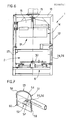
- the centering assembly 2 consists of four centering arms 20, 21, 22 and 23 arranged in pairs facing each other on the cutting table 10. These arms are entirely offset and pivotally mounted two by two on vertical connecting axes 24, 25, 26 and 27 on edge supports 28 and 29 fixed to the edge profiles of the conveyor belt 8 at the cutting table 10.
- centering assembly 2 and its routing mechanism 6 consist of the following members and elements appearing in detail in FIGS. 4 and 5.
- a central rotary plate 30 disposed under the cutting table (FIG. 4) is pivotally mounted around a central axis 31 carried by a hub 32. This plate is actuated in rotation by an adjacent double-acting cylinder 33 whose rod 34 is articulated at the lateral end of the rotary plate 30 to produce a tangential thrust.
- Said tray has a generally rectangular shape. It has on either side of its center two symmetrical curvilinear lights 35 and 36 for example parabolic delimiting guide openings along each of which the element circulates director of a translation device 37 or 38 actuating the pivoting of the arms.
- the steering element will for example be a roller 39 or 40 moving along the lights 35 or 36, the edges of which serve as raceways.
- the curvilinear line of these edges makes it possible to drive the moving equipment or slides 41 and 42 of the translation devices in front or rear translation and thus to actuate the arms in pivoting movements of approaching or moving away.
- the translation devices 37 or 38 consist for each group of arms of two control rods respectively 43, 44 and 45, 46 arranged in a V with a point directed towards the plate.
- the rods of each group are articulated in common at their end on the plate side to the axis carrying the rollers 39 or 40 and are pivotally connected to the vertical connecting axes 24 to 27 controlling the centering arms of each group by the intermediate articulated levers 47, 48 and 49, 50.
- These links transmit an overall convergence movement towards the center by a single command for the centering arms which are subject to the same actuation plate ensuring coordination and simultaneity movements.
- the centering arms are shaped at the end according to a domed head such as 51 and provided with contact and thrust detector sensors, identical such as 52, shown in isolation in FIG. 6.
- detectors are housed in the end head 51 comprising a convex face 53 provided with an opening 54 through which passes a movable element 55 sensitive to pressure, for example with roller 56, coming from a contact switch or contactor 57, housed in the end head 51.
- This switch is connected to the control circuit of the machine.
- the detection head comprises on the curved front face 53 a flexible screen 58 also curved, fixed to only one of its transverse ends 59 capable of bending around said end 59 relative to its other end left free 60.
- This screen constitutes on the one hand a protection for the sensitive member of the detector which is the switch 57 and on the other hand a shock and contact damper. Its deflection in flexion constitutes the necessary deflection of the contactor 57 between an open state and a closed state corresponding to an extended or withdrawn position of its feeler element.
- the gruyère cheese is brought to the entrance of the mat approximately centered, that is to say discharged at equal distance from the edges. It is brought by the conveyor belt to the cutting table 10 in the area swept by the centering arms which are then open.
- the first arm in contact with the body of the wheel makes it slide laterally until contact with one of the other arms which, by reaction, pushes it towards the center.
- the perimeter of action of the arms tightening the wheel is subject to simultaneous centripetal pushes which force it into a perfectly central position.
- Force sensors transmit force thrust and when this exceeds a predetermined value the control cabinet cancels the pressure on the jack.
- the grinding wheel remains caught in the vice of the centering arms and is released by the withdrawal of the arms following the reverse rotation of the arms under the effect of the opposite pressure applied to the jack.
- Cutting can take place.
- the lowering of the blade holder is controlled and the knives slice the grinding wheel according to the desired cutting path.
- the cut pieces fall but do not individualize.
- the wheel is then evacuated by the conveyor belt to the end from where it is taken up manually or by another conveyor or conveyor to a packing station.
Landscapes
- Engineering & Computer Science (AREA)
- Mechanical Engineering (AREA)
- Life Sciences & Earth Sciences (AREA)
- Forests & Forestry (AREA)
- Control Of Cutting Processes (AREA)
- Finish Polishing, Edge Sharpening, And Grinding By Specific Grinding Devices (AREA)
- Dovetailed Work, And Nailing Machines And Stapling Machines For Wood (AREA)
- Treatment Of Fiber Materials (AREA)
Priority Applications (1)
| Application Number | Priority Date | Filing Date | Title |
|---|---|---|---|
| AT87440033T ATE59322T1 (de) | 1986-06-06 | 1987-06-05 | Vorrichtung zum automatischen zentrieren eines produktes unter einem schneidkopf. |
Applications Claiming Priority (2)
| Application Number | Priority Date | Filing Date | Title |
|---|---|---|---|
| FR8608326 | 1986-06-06 | ||
| FR8608326A FR2599658B1 (fr) | 1986-06-06 | 1986-06-06 | Ensemble de centrage automatique d'un produit sous une tete de decoupe |
Publications (2)
| Publication Number | Publication Date |
|---|---|
| EP0248751A1 true EP0248751A1 (de) | 1987-12-09 |
| EP0248751B1 EP0248751B1 (de) | 1990-12-27 |
Family
ID=9336160
Family Applications (1)
| Application Number | Title | Priority Date | Filing Date |
|---|---|---|---|
| EP87440033A Expired - Lifetime EP0248751B1 (de) | 1986-06-06 | 1987-06-05 | Vorrichtung zum automatischen Zentrieren eines Produktes unter einem Schneidkopf |
Country Status (4)
| Country | Link |
|---|---|
| EP (1) | EP0248751B1 (de) |
| AT (1) | ATE59322T1 (de) |
| DE (1) | DE3767039D1 (de) |
| FR (1) | FR2599658B1 (de) |
Cited By (7)
| Publication number | Priority date | Publication date | Assignee | Title |
|---|---|---|---|---|
| EP0437018A3 (en) * | 1990-01-10 | 1991-12-11 | Silicon Technology Corporation | A wafer centering assembly |
| EP0539842A1 (de) * | 1991-10-31 | 1993-05-05 | Heinrich Zeidler, Maschinenfabrik GmbH & Co.KG | Schleifvorrichtung für keramische Gegenstände, insbesondere Teller und ähnliches Flachgeschirr |
| CN102152261A (zh) * | 2011-03-28 | 2011-08-17 | 上海大学 | 用于汽车传动轴自动压装专机的对中定位与自锁夹紧装置 |
| GB2481062A (en) * | 2010-06-11 | 2011-12-14 | Long Clawson Dairy Ltd | An apparatus and method for decrusting a cheese |
| CN112706133A (zh) * | 2020-12-09 | 2021-04-27 | 福建鑫源泰新型材料有限公司 | 一种木纹铝单板加工定位装置 |
| CN113103325A (zh) * | 2021-03-12 | 2021-07-13 | 浙江中医药大学中药饮片有限公司 | 一种自清洁式离心切药机 |
| CN115383494A (zh) * | 2022-09-30 | 2022-11-25 | 铜陵格里赛铜冠电子材料有限公司 | 一种异型铜带自动剪切机构 |
Citations (5)
| Publication number | Priority date | Publication date | Assignee | Title |
|---|---|---|---|---|
| DE484595C (de) * | 1927-11-12 | 1929-10-21 | Franz Hennemeyer | Vorrichtung zum Zerschneiden von Torten in keilfoermige Teile |
| US1800706A (en) * | 1928-02-14 | 1931-04-14 | Carl E Turnquist | Automatic pie and cake dividing machine |
| US2901085A (en) * | 1958-12-08 | 1959-08-25 | Carando Machine Works | Elevating and centering device for cylindrical bodies |
| FR2228583A1 (de) * | 1973-05-07 | 1974-12-06 | Unilever Nv | |
| DE2626206A1 (de) * | 1976-06-11 | 1977-12-22 | Krupp Gmbh | Greiferanordnung |
Family Cites Families (1)
| Publication number | Priority date | Publication date | Assignee | Title |
|---|---|---|---|---|
| JPS6030539A (ja) * | 1983-07-29 | 1985-02-16 | Amada Co Ltd | グリッパフイ−ド装置 |
-
1986
- 1986-06-06 FR FR8608326A patent/FR2599658B1/fr not_active Expired
-
1987
- 1987-06-05 DE DE8787440033T patent/DE3767039D1/de not_active Expired - Fee Related
- 1987-06-05 AT AT87440033T patent/ATE59322T1/de not_active IP Right Cessation
- 1987-06-05 EP EP87440033A patent/EP0248751B1/de not_active Expired - Lifetime
Patent Citations (5)
| Publication number | Priority date | Publication date | Assignee | Title |
|---|---|---|---|---|
| DE484595C (de) * | 1927-11-12 | 1929-10-21 | Franz Hennemeyer | Vorrichtung zum Zerschneiden von Torten in keilfoermige Teile |
| US1800706A (en) * | 1928-02-14 | 1931-04-14 | Carl E Turnquist | Automatic pie and cake dividing machine |
| US2901085A (en) * | 1958-12-08 | 1959-08-25 | Carando Machine Works | Elevating and centering device for cylindrical bodies |
| FR2228583A1 (de) * | 1973-05-07 | 1974-12-06 | Unilever Nv | |
| DE2626206A1 (de) * | 1976-06-11 | 1977-12-22 | Krupp Gmbh | Greiferanordnung |
Non-Patent Citations (2)
| Title |
|---|
| PATENT ABSTRACTS OF JAPAN, vol. 9, no. 155 (M-392)[1878], 29 juin 1985; & JP-A-60 30 539 (AMADA K.K.) 16-02-1985 * |
| VOEDING EN TECHNIEK, vol. 1, no. 27, 1 novembre 1967, pages 687-688, Zeist, NL; "Kaasdeelmachine, een interessante Nederlandse ontwikkeling" * |
Cited By (10)
| Publication number | Priority date | Publication date | Assignee | Title |
|---|---|---|---|---|
| EP0437018A3 (en) * | 1990-01-10 | 1991-12-11 | Silicon Technology Corporation | A wafer centering assembly |
| EP0539842A1 (de) * | 1991-10-31 | 1993-05-05 | Heinrich Zeidler, Maschinenfabrik GmbH & Co.KG | Schleifvorrichtung für keramische Gegenstände, insbesondere Teller und ähnliches Flachgeschirr |
| GB2481062A (en) * | 2010-06-11 | 2011-12-14 | Long Clawson Dairy Ltd | An apparatus and method for decrusting a cheese |
| GB2481062B (en) * | 2010-06-11 | 2014-07-02 | Long Clawson Dairy Ltd | An apparatus and method for processing a cheese |
| CN102152261A (zh) * | 2011-03-28 | 2011-08-17 | 上海大学 | 用于汽车传动轴自动压装专机的对中定位与自锁夹紧装置 |
| CN112706133A (zh) * | 2020-12-09 | 2021-04-27 | 福建鑫源泰新型材料有限公司 | 一种木纹铝单板加工定位装置 |
| CN113103325A (zh) * | 2021-03-12 | 2021-07-13 | 浙江中医药大学中药饮片有限公司 | 一种自清洁式离心切药机 |
| CN113103325B (zh) * | 2021-03-12 | 2022-07-19 | 浙江中医药大学中药饮片有限公司 | 一种自清洁式离心切药机 |
| CN115383494A (zh) * | 2022-09-30 | 2022-11-25 | 铜陵格里赛铜冠电子材料有限公司 | 一种异型铜带自动剪切机构 |
| CN115383494B (zh) * | 2022-09-30 | 2023-07-11 | 铜陵格里赛铜冠电子材料有限公司 | 一种异型铜带自动剪切机构 |
Also Published As
| Publication number | Publication date |
|---|---|
| FR2599658B1 (fr) | 1988-10-21 |
| EP0248751B1 (de) | 1990-12-27 |
| ATE59322T1 (de) | 1991-01-15 |
| DE3767039D1 (de) | 1991-02-07 |
| FR2599658A1 (fr) | 1987-12-11 |
Similar Documents
| Publication | Publication Date | Title |
|---|---|---|
| US4050339A (en) | Automatic carousel-type meat cutting machine | |
| US4344268A (en) | Bag slitting apparatus | |
| FR2502464A1 (fr) | Appareil de separation du cou des volailles plumees et etetees | |
| FR2663877A1 (fr) | Machine automatique a trancher des produits non rigides comme des matieres alimentaires telles que des viandes. | |
| FR2575914A1 (de) | ||
| US5477662A (en) | Device for packaging products in bags | |
| EP0177391B1 (de) | Siebdruckmaschine | |
| EP0248751B1 (de) | Vorrichtung zum automatischen Zentrieren eines Produktes unter einem Schneidkopf | |
| FR2674787A1 (fr) | Machine de coupe et table de reception combinees. | |
| EP0483006A1 (de) | Maschine zum Entstrunken von Gemüsen wie Broccoli | |
| EP0155881B1 (de) | Verfahren und Vorrichtung zum Entkrusten und Schneiden von Käselaiben | |
| EP0018868B1 (de) | Vorrichtung zum in der Längsrichtung Schneiden von Brammen mittels Sauerstoffbrennschneiden | |
| FR2498557A1 (fr) | Machine a emballer des objets de forme sensiblement cylindrique dans des feuilles decoupees selon un contour ferme dans des bandes d'un materiau souple d'emballage | |
| EP0389321A1 (de) | Ballensammelgerät | |
| EP0014135B1 (de) | Vorrichtungen zum in Scheiben schneiden von Lachs | |
| FR2801768A1 (fr) | Machine pour preparer les jambons crus seches en vue du desossement | |
| FR2591420A1 (fr) | Desileuse a griffe | |
| FR2628685A1 (fr) | Machine a relier des liasses de feuilles par brochage | |
| FR2645065A1 (fr) | Procede pour trancher en secteurs un produit alimentaire, notamment du type fromage et le dispositif de mise en oeuvre | |
| FR2661350A1 (fr) | Machine pour decouper en tranches un produit alimentaire moule. | |
| EP0611519A1 (de) | Pflanzmaschine für Erdballen-Setzlinge | |
| FR2811605A1 (fr) | Dispositif pour la separation de produits scies, en sortie d'une deligneuse | |
| CA1084815A (en) | Machine for slicing salmon | |
| EP0320392B1 (de) | Vorrichtung zur gleichzeitigen Thermoformung von mindestens einer Reihe von Behältern aus thermoplastischem Kunststoff mit einer dekorativen Banderole | |
| FR2766334A1 (fr) | Installation pour parer les brocolis |
Legal Events
| Date | Code | Title | Description |
|---|---|---|---|
| PUAI | Public reference made under article 153(3) epc to a published international application that has entered the european phase |
Free format text: ORIGINAL CODE: 0009012 |
|
| AK | Designated contracting states |
Kind code of ref document: A1 Designated state(s): AT BE CH DE LI LU NL SE |
|
| 17P | Request for examination filed |
Effective date: 19880606 |
|
| 17Q | First examination report despatched |
Effective date: 19890822 |
|
| GRAA | (expected) grant |
Free format text: ORIGINAL CODE: 0009210 |
|
| AK | Designated contracting states |
Kind code of ref document: B1 Designated state(s): AT BE CH DE LI LU NL SE |
|
| PG25 | Lapsed in a contracting state [announced via postgrant information from national office to epo] |
Ref country code: SE Free format text: THE PATENT HAS BEEN ANNULLED BY A DECISION OF A NATIONAL AUTHORITY Effective date: 19901227 |
|
| REF | Corresponds to: |
Ref document number: 59322 Country of ref document: AT Date of ref document: 19910115 Kind code of ref document: T |
|
| REF | Corresponds to: |
Ref document number: 3767039 Country of ref document: DE Date of ref document: 19910207 |
|
| PLBE | No opposition filed within time limit |
Free format text: ORIGINAL CODE: 0009261 |
|
| STAA | Information on the status of an ep patent application or granted ep patent |
Free format text: STATUS: NO OPPOSITION FILED WITHIN TIME LIMIT |
|
| 26N | No opposition filed | ||
| REG | Reference to a national code |
Ref country code: CH Ref legal event code: PL |
|
| REG | Reference to a national code |
Ref country code: CH Ref legal event code: PK |
|
| PGFP | Annual fee paid to national office [announced via postgrant information from national office to epo] |
Ref country code: CH Payment date: 19920511 Year of fee payment: 6 |
|
| PGFP | Annual fee paid to national office [announced via postgrant information from national office to epo] |
Ref country code: AT Payment date: 19920515 Year of fee payment: 6 |
|
| PGFP | Annual fee paid to national office [announced via postgrant information from national office to epo] |
Ref country code: BE Payment date: 19920519 Year of fee payment: 6 |
|
| PGFP | Annual fee paid to national office [announced via postgrant information from national office to epo] |
Ref country code: LU Payment date: 19920527 Year of fee payment: 6 Ref country code: DE Payment date: 19920527 Year of fee payment: 6 |
|
| PGFP | Annual fee paid to national office [announced via postgrant information from national office to epo] |
Ref country code: NL Payment date: 19920630 Year of fee payment: 6 |
|
| EPTA | Lu: last paid annual fee | ||
| PG25 | Lapsed in a contracting state [announced via postgrant information from national office to epo] |
Ref country code: LU Free format text: LAPSE BECAUSE OF NON-PAYMENT OF DUE FEES Effective date: 19930605 Ref country code: AT Effective date: 19930605 |
|
| PG25 | Lapsed in a contracting state [announced via postgrant information from national office to epo] |
Ref country code: LI Effective date: 19930630 Ref country code: CH Effective date: 19930630 Ref country code: BE Effective date: 19930630 |
|
| BERE | Be: lapsed |
Owner name: ETS GUY RIONDE Effective date: 19930630 |
|
| PG25 | Lapsed in a contracting state [announced via postgrant information from national office to epo] |
Ref country code: NL Effective date: 19940101 |
|
| NLV4 | Nl: lapsed or anulled due to non-payment of the annual fee | ||
| REG | Reference to a national code |
Ref country code: CH Ref legal event code: PL |
|
| PG25 | Lapsed in a contracting state [announced via postgrant information from national office to epo] |
Ref country code: DE Effective date: 19940301 |