EP0248986A1 - Actionneur hydraulique à clapet oscillant - Google Patents
Actionneur hydraulique à clapet oscillant Download PDFInfo
- Publication number
- EP0248986A1 EP0248986A1 EP87104197A EP87104197A EP0248986A1 EP 0248986 A1 EP0248986 A1 EP 0248986A1 EP 87104197 A EP87104197 A EP 87104197A EP 87104197 A EP87104197 A EP 87104197A EP 0248986 A1 EP0248986 A1 EP 0248986A1
- Authority
- EP
- European Patent Office
- Prior art keywords
- shaft
- housing
- vanes
- vane
- rotary vane
- Prior art date
- Legal status (The legal status is an assumption and is not a legal conclusion. Google has not performed a legal analysis and makes no representation as to the accuracy of the status listed.)
- Granted
Links
- 239000012530 fluid Substances 0.000 claims abstract description 23
- 238000007789 sealing Methods 0.000 claims description 12
- 239000000463 material Substances 0.000 description 6
- 239000004809 Teflon Substances 0.000 description 3
- 229920006362 Teflon® Polymers 0.000 description 3
- 238000004519 manufacturing process Methods 0.000 description 3
- 239000002184 metal Substances 0.000 description 3
- 239000004963 Torlon Substances 0.000 description 2
- 229920003997 Torlon® Polymers 0.000 description 2
- 238000010276 construction Methods 0.000 description 2
- 229920003223 poly(pyromellitimide-1,4-diphenyl ether) Polymers 0.000 description 2
- 230000003068 static effect Effects 0.000 description 2
- 230000002411 adverse Effects 0.000 description 1
- 230000003190 augmentative effect Effects 0.000 description 1
- 230000004323 axial length Effects 0.000 description 1
- 229920002457 flexible plastic Polymers 0.000 description 1
- 238000009434 installation Methods 0.000 description 1
- 229920001343 polytetrafluoroethylene Polymers 0.000 description 1
- 239000007787 solid Substances 0.000 description 1
- 230000002277 temperature effect Effects 0.000 description 1
Images

Classifications
-
- F—MECHANICAL ENGINEERING; LIGHTING; HEATING; WEAPONS; BLASTING
- F15—FLUID-PRESSURE ACTUATORS; HYDRAULICS OR PNEUMATICS IN GENERAL
- F15B—SYSTEMS ACTING BY MEANS OF FLUIDS IN GENERAL; FLUID-PRESSURE ACTUATORS, e.g. SERVOMOTORS; DETAILS OF FLUID-PRESSURE SYSTEMS, NOT OTHERWISE PROVIDED FOR
- F15B15/00—Fluid-actuated devices for displacing a member from one position to another; Gearing associated therewith
- F15B15/08—Characterised by the construction of the motor unit
- F15B15/12—Characterised by the construction of the motor unit of the oscillating-vane or curved-cylinder type
Definitions
- This invention relates to rotary vane hydraulic actuators and more particularly to such an actuator designed to operate within the confines of thin wings or control surfaces of modern aircraft.
- a rotary vane actuator normally includes a housing connected to a source of fluid under pressure, a chamber within the housing, a shaft passing through the housing and vane members attached to the shaft and moveable in the housing in one direction or the other in response to directed hydraulic fluid under pressure to cause rotation of said shaft, usually over a limited travel such as ⁇ forty degrees.
- a control surface may be attached to the shaft and movable therewith. Suitable seals must be employed to prevent excessive leakage and loss of power.
- Such rotary vane hydraulic actuators are not new but have come into greater use recently because of advantages as compared with linear actuators for operating control surfaces of aircraft where the space available for the actuator is very limited. Because of the shape of an airfoil such as a wing, for example, it may be advantageous to incorporate a rotary vane actuator which can operate along the hinge line of a movable surface such as an aileron rather than a linear cylinder which may require increasing the thickness of the wing or adding protrusions to the wing to contain the actuator. Recent trends toward unusually thin wing construction for supersonic aircraft has made interest in the rotary actuator even greater because such protrusions or extra thickness adversely affect the performance of the aircraft.
- the rotary vane hydraulic actuator of the present invention has a generally cylindrical housing having endcaps with flattened walls top and bottom to minimize its height and including a pair of elongated ribs internally of the flattened walls which have arcuate surfaces acting in cooperation with the operating shaft to effectively divide the internal chamber of the housing into what might be termed left and right chambers.
- the shaft carries oppositely directed vanes, one in each of the left and right chambers, which vanes are quite thick and have an arcuate surface of substantial length adjacent the internal walls of the left and right chambers.
- a pair of elongated dynamic seals are carried in grooves in the internal walls of the chamber and also in the endcaps such that they seal radially against the arcuate surfaces of the vanes and also axially against the end surfaces of the vanes.
- Other dynamic seals are carried in the arcuate surfaces of the internal ribs such that they seal against the shaft.
- Additional static seals are positioned between the housing and endcaps. Dynamic seals are also incorporated into the endcaps to seal against the rotatable shaft.
- the dynamic seals are carried in the housing and seal against the surfaces of the vanes and the shaft which have minimal distortion as a function of pressure differentials.
- the seals themselves are of flexible materials such as polytetrafluoroethylene (Teflon), filled Teflon, or polymides such as Vespel or Torlon which will maintain contact by their inherent characteristics or they may be augmented by means of additional spring-type expander members in the seal grooves to provide mechanical spring loading to assure contact with the vanes and shaft.
- the seals against the vanes are preferably single piece seals which have 90 degree corner projections to assure radial contact on the vane outer diameter and axial contact on the vane end faces. Sufficient end length interference must be provided to accommodate the differential expansion of the seal material and vane material over the required temperature range.
- Advantages of the present invention are that it provides a vane type linear actuator which has a low height such that it can be placed along a hinge line of control surfaces of thin wing aircraft, it affords a sealing arrangement allowing for minimum leakage at high operating pressures despite physical distortion of the housing with pressure variations and yet the actuator is not excessively costly to manufacture.
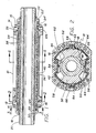
- a generally cylindrical housing or barrel l0 is shown having endcaps l2 and l4 attached thereto by means of screws l6.
- a shaft l8 is supported in the endcaps l2, l4 which carry dynamic seals 22, 24 and 22 ⁇ , 24 ⁇ , respectively, consisting of combination O-rings and low friction rings in contact with shaft 20.
- a pair of static seals 26 and 28 are positoned between endcaps l2 and l4, respectively, and the cylinder barrel l0.
- Shaft 20 actually includes two concentric cylindrical parts including an inner splined output drive member 20 held in axial alignment with member l8 by means of wire retainers 30, 32.
- shaft 20 may be made of a single piece with a spline output.
- shaft seals 34 and 36 Carried in slots in barrel l0 and extending into the endcaps l2 and l4 are a pair of elongated shaft seals 34 and 36. These seals are preferably of a flexible plastic material having low friction such as polytetraflouroethelyne (Teflon or filled Teflon) or polymides (such as Vespel or Torlon).
- Shaft seals 34 and 36 should preferably have an interference fit with or insert in grooves formed in additional ring seals l05 surrounding shaft 20 at each endcap.
- FIG. 2 is a cross sectional view taken along line 2-2 of Figure l.
- barrel l0 is formed with parallel flattened surfaces top and bottom and that a pair of inwardly extending ribs 42, 44 are formed on the inside of the barrel directly opposite the flattened sides.
- Seals 34 and 36 are carried in longitudinal grooves in ribs 42, 44 which have arcuate surfaces 46, 48 respectively adjacent the surface of shaft l8 such that the seals 34, 36 seal against the shaft.
- Carried on shaft l8 and extending radially into the interior of barrel l0 are a pair of vanes 50, 52 which have considerable thickness and which terminate in arcuate surfaces 54, 56, respectively.
- Each of vanes 50, 52 serves to separate the half of the internal part of barrel l0 in which it is located into two chambers, vane 50 separating chambers 58 and 60 and vane 52 separating chambers 62 and 64.
- elongated dynamic seals 66 and 68 which seal against the arcuate surfaces 54 and 56, respectively. These seals are, or may be, essentially the same as shaft seals 34 and 36, and may also include metal spring members to assure contact against the surfaces 54 and 56 irrespective of internal pressures which may tend to distort barrel l0. Also visible in this view are the seal 26, described above and the several threaded holes for receiving screws l6.
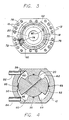
- FIG. 3 is a sectional view taken along line 3-3 of Figure l and gives some detail of the endcap l2 and its internal passages.
- a boss 70 having an internal port 72 which is suitably connected to a conduit, not shown, from a source of operating fluid under pressure.
- Boss 70 communicates with an axially directed passage 74 which is connected to chamber 60 and also with channels 76 and 78 which communicate with a second axially directed passage 80 which communicates with chamber 62.
- the channels 76 and 78 are preferably located between shaft seals 22 and 24 or 22 ⁇ and 24 ⁇ . Passages 74 and 80 must be located away from shaft 20 so that they do no intersect with the seal grooves.
- FIG 4 is a schematic drawing showing an alternative porting arrangement for my rotary vane hydraulic actuator.
- a pair of fluid passages 82 and 84 which communicate with a high pressure source are connected to chamber 58 and 60 respectively.
- a pair of non-intersecting diagonal ports 86 and 88 are drilled through a solid portion of shaft 20 such that high pressure in chamber 58 will be communicated through passage 86 to chamber 64 and at the same time passage 84 will communicate with the low pressure side of the fluid pressure source. This low pressure will also be communicated through port 88 with chamber 62 which would cause the vanes to move counterclockwise.
- Figure 5 is a partial sectional view showing details of the vane seals and showing the manner in which the seal seals against the vane both along its axial length and against its ends.
- the shaft l8 carries vane 50 which makes contact against seal 66.
- Seal 66 is carried in barrel l0 through its length and extends into slots 70 and 72 in endcaps l2 and l4, respectively, making 90 degree corner projections at the ends.
- the seal member 66 may be backed by metal springs or expander members to assure sealing contact against the vane despite some distortion of the barrel l0.
- Sufficient end length interference is provided to account for the differential expansion of the seal material and vane material over the required temperature range.
- This end section will also engage in an interference fit slot on seal rings l05 in the end caps l2 and l4 to provide axial sealing of the shaft, i.e. prevent leaking from one chamber to the adjacent chamber at the shaft ends.
- Figure 6 is a partial sectional view similar to Figure 5, but displaced approximately ninety degrees to show details of the shaft seal 34 and associated structure.
- seal 34 and back up springs or expander members 38 are carried in a slot in the longitudinal rib 34 which is part of barrel l0.
- Seal 34 extends into notches in ring seals l05 in endcaps l2 and l4 or otherwise makes an interference fit against the seals l05 to provide axial sealing as described above.
- the above described actuator would typically be attached to the main shaft of a control surface forming part of a wing, for example, and would turn the output shaft over a range of up to about forty degrees.
- the height of the actuator can be reduced substantially to fit within a thin wing or control surface.
- the longitudinal ribs 42 and 44 provide strength and stiffness to the barrel l0 while also providing means for sealing between operating chambers containing hydraulic fluid.
- the thick vanes 50 and 52 include arcuate surfaces of such length that the seals 66 and 68 maintain contact against the vanes at all travel positions of the vane.
- FIG. 7 is a sectional view of another embodiment of my invention utilizing a single vane.
- This embodiment can be made in a form having even less height for installation in thin section wings or control surfaces.
- a housing 90 includes an internal cavity 92 which contains a rotatable shaft 94 effectively separated into chambers 96 and 98 by a single vane l00 carried on the shaft.
- Carried in housing 90 are a single shaft seal l02 and a single vane seal l04 which are of the same type and which seal in the same manner as do shaft seals 34, 36 and vane seals 66, 68.
- Vane l00 has a long arcuate surface as do vanes 50, 52 so that the sealing engagement is maintained over the entire travel of vane l00.
- a pair of ports l06 and l08 are connected to a control valve directing fluid under high pressure to chamber 96 and returning to the low pressure side of the fluid source from chamber 98 to cause clockwise rotation of the shaft 94, or directing high pressure fluid to chamber 98 and connecting chamber 96 to the low pressure return side of the source to cause counter-clockwise rotation of shaft 94.
- the vane seal l04 extends along the length of vane l00 and on the end faces as described with respect to Figure 5.
- the shaft seal is essentially as described with respect to Figure 6.
- these endcaps also include slots which carry the ninety degree projections of the vane seals l04 which seal against the ends of vane l00.
- This single vane embodiment has a practical travel limitation of about ⁇ eighty degrees rotation; however, it is most useful as a flat pack wherein the rotation is limited to not more than about ⁇ thirty degrees from center. It will have higher friction than the two vane embodiment since it is not balanced around the center but will fit in some locations where the two vane actuator will not fit.
- actuators offer several advantages. Although they have a low height to fit into thin wing sections, they may be made comparatively long so that the high pressure will operate on a substantial area and provide a high actuating force. The use of only one or two vanes simplifies sealing problems and reduces costs. Where space requirements dictate, it is not impractical to make a two vane actuator with one vane longer then the other. By placing the longitudinal internal ribs opposite the flattened barrel portions, the barrel is strengthened in an area where it might otherwise be thin and subject to distortion.
- the vane seals and shaft seals are both dynamic seals which are carried in the stationary barrel and endcaps rather than on movable parts such as the vanes and these seals may be backed by spring members or expanders to force the seals into contact with the opposing movable surfaces despite any distortion in the housing which might be caused by the large operating pressure variations. It will thus be apparent that the above actuator, while having the desired limited height, is simple and rugged in construction, and provides an effective sealing structure to minimize fluid leakage losses despite operating a substantially higher fluid pressures than are currently in general use.
Landscapes
- Engineering & Computer Science (AREA)
- Physics & Mathematics (AREA)
- Fluid Mechanics (AREA)
- Mechanical Engineering (AREA)
- General Engineering & Computer Science (AREA)
- Actuator (AREA)
Applications Claiming Priority (2)
| Application Number | Priority Date | Filing Date | Title |
|---|---|---|---|
| US87194486A | 1986-06-09 | 1986-06-09 | |
| US871944 | 1986-06-09 |
Publications (2)
| Publication Number | Publication Date |
|---|---|
| EP0248986A1 true EP0248986A1 (fr) | 1987-12-16 |
| EP0248986B1 EP0248986B1 (fr) | 1992-03-04 |
Family
ID=25358509
Family Applications (1)
| Application Number | Title | Priority Date | Filing Date |
|---|---|---|---|
| EP19870104197 Expired EP0248986B1 (fr) | 1986-06-09 | 1987-03-21 | Actionneur hydraulique à clapet oscillant |
Country Status (3)
| Country | Link |
|---|---|
| EP (1) | EP0248986B1 (fr) |
| JP (1) | JPS62292902A (fr) |
| DE (1) | DE3776972D1 (fr) |
Cited By (16)
| Publication number | Priority date | Publication date | Assignee | Title |
|---|---|---|---|---|
| DE4435491A1 (de) * | 1993-11-05 | 1995-05-11 | Fichtel & Sachs Ag | Stabilisatoranordnung mit einem Schwenkmotor |
| US5573265A (en) * | 1993-11-05 | 1996-11-12 | Fichtel & Sachs Ag | Stabilizer system for a motor vehicle suspension system with a rotary actuator |
| EP0957270A3 (fr) * | 1998-05-13 | 2001-03-14 | bar-pneumatische Steuerungssysteme GmbH | Entraínement pivotant pour actionner une robinetterie |
| DE102006014018A1 (de) * | 2006-03-27 | 2007-10-04 | Robert Bosch Gmbh | Hydraulischer Schwenkmotor |
| ITBO20090194A1 (it) * | 2009-03-27 | 2010-09-28 | Rovel S R L | Attuatore azionato da un fluido in pressione |
| DE102011118321A1 (de) | 2011-11-11 | 2013-05-16 | Liebherr-Aerospace Lindenberg Gmbh | Hydraulischer Rotationsantrieb |
| WO2015031587A1 (fr) | 2013-08-29 | 2015-03-05 | Llc Vector Horizon Technologies | Actionneur électro-hydraulique |
| WO2015071304A1 (fr) * | 2013-11-13 | 2015-05-21 | C. & E. Fein Gmbh | Machine-outil pouvant être entraînée en oscillation |
| WO2016140959A1 (fr) | 2015-03-02 | 2016-09-09 | Vector Horizon Technologies, Llc | Ensemble soupape et procédé de refroidissement |
| US10072773B2 (en) | 2013-08-29 | 2018-09-11 | Aventics Corporation | Valve assembly and method of cooling |
| CN109996503A (zh) * | 2016-12-28 | 2019-07-09 | 川崎重工业株式会社 | 机器人钳子 |
| US11047506B2 (en) | 2013-08-29 | 2021-06-29 | Aventics Corporation | Valve assembly and method of cooling |
| EP3816456A4 (fr) * | 2018-06-26 | 2022-03-09 | Kawasaki Jukogyo Kabushiki Kaisha | Actionneur rotatif et forceps robotique |
| CN119773959A (zh) * | 2025-03-12 | 2025-04-08 | 北京航辰机载智能系统科技有限公司 | 一种用于薄机翼飞机舵面驱动的电静液马达作动器 |
| CN119821661A (zh) * | 2025-03-14 | 2025-04-15 | 北京航辰机载智能系统科技有限公司 | 一种分区密封的叶片式航空作动器 |
| CN119821662A (zh) * | 2025-03-14 | 2025-04-15 | 北京航辰机载智能系统科技有限公司 | 一种用于驱动飞机舵面旋转的液压摆动马达 |
Families Citing this family (1)
| Publication number | Priority date | Publication date | Assignee | Title |
|---|---|---|---|---|
| JP2560857Y2 (ja) * | 1990-11-19 | 1998-01-26 | 住友精密工業 株式会社 | ロータリアクチュエータ |
Citations (4)
| Publication number | Priority date | Publication date | Assignee | Title |
|---|---|---|---|---|
| US2984221A (en) * | 1958-07-01 | 1961-05-16 | Douglas Aircraft Co Inc | Rotary actuator |
| GB1036829A (en) * | 1963-09-17 | 1966-07-20 | Houdaille Industries Inc | Improvements in or relating to semi-rotary hydraulic actuators |
| FR2492908A1 (fr) * | 1980-10-29 | 1982-04-30 | Renault | Verin rotatif d'asservissement |
| DE3222982A1 (de) * | 1982-06-19 | 1983-12-22 | Südhydraulik Kork-Steinbach GmbH & Co KG, 2400 Lübeck | Drehkolbenzylinder |
-
1987
- 1987-03-21 DE DE8787104197T patent/DE3776972D1/de not_active Expired - Lifetime
- 1987-03-21 EP EP19870104197 patent/EP0248986B1/fr not_active Expired
- 1987-05-29 JP JP13473587A patent/JPS62292902A/ja active Pending
Patent Citations (4)
| Publication number | Priority date | Publication date | Assignee | Title |
|---|---|---|---|---|
| US2984221A (en) * | 1958-07-01 | 1961-05-16 | Douglas Aircraft Co Inc | Rotary actuator |
| GB1036829A (en) * | 1963-09-17 | 1966-07-20 | Houdaille Industries Inc | Improvements in or relating to semi-rotary hydraulic actuators |
| FR2492908A1 (fr) * | 1980-10-29 | 1982-04-30 | Renault | Verin rotatif d'asservissement |
| DE3222982A1 (de) * | 1982-06-19 | 1983-12-22 | Südhydraulik Kork-Steinbach GmbH & Co KG, 2400 Lübeck | Drehkolbenzylinder |
Cited By (25)
| Publication number | Priority date | Publication date | Assignee | Title |
|---|---|---|---|---|
| DE4435491A1 (de) * | 1993-11-05 | 1995-05-11 | Fichtel & Sachs Ag | Stabilisatoranordnung mit einem Schwenkmotor |
| US5573265A (en) * | 1993-11-05 | 1996-11-12 | Fichtel & Sachs Ag | Stabilizer system for a motor vehicle suspension system with a rotary actuator |
| US5580079A (en) * | 1993-11-05 | 1996-12-03 | Fichtel & Sachs Ag | Rotary actuator with stabilizer in a motor vehicle suspension system |
| EP0957270A3 (fr) * | 1998-05-13 | 2001-03-14 | bar-pneumatische Steuerungssysteme GmbH | Entraínement pivotant pour actionner une robinetterie |
| DE102006014018A1 (de) * | 2006-03-27 | 2007-10-04 | Robert Bosch Gmbh | Hydraulischer Schwenkmotor |
| ITBO20090194A1 (it) * | 2009-03-27 | 2010-09-28 | Rovel S R L | Attuatore azionato da un fluido in pressione |
| DE102011118321A1 (de) | 2011-11-11 | 2013-05-16 | Liebherr-Aerospace Lindenberg Gmbh | Hydraulischer Rotationsantrieb |
| DE102011118321B4 (de) | 2011-11-11 | 2023-01-19 | Liebherr-Aerospace Lindenberg Gmbh | Hydraulischer Rotationsantrieb |
| US10072773B2 (en) | 2013-08-29 | 2018-09-11 | Aventics Corporation | Valve assembly and method of cooling |
| US10359061B2 (en) | 2013-08-29 | 2019-07-23 | Aventics Corporation | Electro-hydraulic actuator |
| WO2015031587A1 (fr) | 2013-08-29 | 2015-03-05 | Llc Vector Horizon Technologies | Actionneur électro-hydraulique |
| US9897114B2 (en) | 2013-08-29 | 2018-02-20 | Aventics Corporation | Electro-hydraulic actuator |
| US11047506B2 (en) | 2013-08-29 | 2021-06-29 | Aventics Corporation | Valve assembly and method of cooling |
| US10093011B2 (en) | 2013-11-13 | 2018-10-09 | C. & E. Fein Gmbh | Oscillatingly driven machine tool |
| WO2015071204A1 (fr) * | 2013-11-13 | 2015-05-21 | C. & E. Fein Gmbh | Machine-outil à entraînement oscillant |
| WO2015071304A1 (fr) * | 2013-11-13 | 2015-05-21 | C. & E. Fein Gmbh | Machine-outil pouvant être entraînée en oscillation |
| WO2016140959A1 (fr) | 2015-03-02 | 2016-09-09 | Vector Horizon Technologies, Llc | Ensemble soupape et procédé de refroidissement |
| CN109996503A (zh) * | 2016-12-28 | 2019-07-09 | 川崎重工业株式会社 | 机器人钳子 |
| EP3563781A4 (fr) * | 2016-12-28 | 2020-08-12 | Kawasaki Jukogyo Kabushiki Kaisha | Pince robotisée |
| EP3816456A4 (fr) * | 2018-06-26 | 2022-03-09 | Kawasaki Jukogyo Kabushiki Kaisha | Actionneur rotatif et forceps robotique |
| CN119773959A (zh) * | 2025-03-12 | 2025-04-08 | 北京航辰机载智能系统科技有限公司 | 一种用于薄机翼飞机舵面驱动的电静液马达作动器 |
| CN119821661A (zh) * | 2025-03-14 | 2025-04-15 | 北京航辰机载智能系统科技有限公司 | 一种分区密封的叶片式航空作动器 |
| CN119821662A (zh) * | 2025-03-14 | 2025-04-15 | 北京航辰机载智能系统科技有限公司 | 一种用于驱动飞机舵面旋转的液压摆动马达 |
| CN119821661B (zh) * | 2025-03-14 | 2025-05-30 | 北京航辰机载智能系统科技有限公司 | 一种分区密封的叶片式航空作动器 |
| CN119821662B (zh) * | 2025-03-14 | 2025-06-27 | 北京航辰机载智能系统科技有限公司 | 一种用于驱动飞机舵面旋转的液压摆动马达 |
Also Published As
| Publication number | Publication date |
|---|---|
| DE3776972D1 (de) | 1992-04-09 |
| EP0248986B1 (fr) | 1992-03-04 |
| JPS62292902A (ja) | 1987-12-19 |
Similar Documents
| Publication | Publication Date | Title |
|---|---|---|
| EP0248986B1 (fr) | Actionneur hydraulique à clapet oscillant | |
| US8011909B2 (en) | Balanced variable displacement vane pump with floating face seals and biased vane seals | |
| US4242065A (en) | Sliding vane compressor with end face inserts or rotor | |
| US6050796A (en) | Vane pump | |
| KR900003715B1 (ko) | 베인형 회전압축기 | |
| US3193190A (en) | Lindberg vacuum pump | |
| US9732771B2 (en) | Hydraulic rotary actuator | |
| US3932073A (en) | Screw rotor machine with spring and fluid biased balancing pistons | |
| US3221665A (en) | Hydraulic pump or motor with hydraulic pressure-responsive vane | |
| KR870006314A (ko) | 가변용량식 베인형 압축기 | |
| CA2066131A1 (fr) | Transmission | |
| KR870005181A (ko) | 가변용량식 베인형 압축기 | |
| US3023741A (en) | Sealed rotary actuator | |
| US3574493A (en) | Vane-type pumps | |
| US5242285A (en) | Cryogenic vane pump | |
| US3943826A (en) | Hydraulic motors and pumps | |
| US6481992B2 (en) | Vane pump | |
| GB2259956A (en) | Turbomachine with variably settable stator blades | |
| US4002033A (en) | Rotary displacer for rotary engines or compressors | |
| KR0148493B1 (ko) | 기어식 유압기계 | |
| US4219315A (en) | Sealing member for orbital or rotary motors | |
| KR900004610B1 (ko) | 베인형 압축기 | |
| RU2222702C2 (ru) | Четырехлинейный гидрораспределитель с плоским поворотным золотником | |
| US4449898A (en) | Power transmission | |
| US3196800A (en) | Gear pump |
Legal Events
| Date | Code | Title | Description |
|---|---|---|---|
| PUAI | Public reference made under article 153(3) epc to a published international application that has entered the european phase |
Free format text: ORIGINAL CODE: 0009012 |
|
| AK | Designated contracting states |
Kind code of ref document: A1 Designated state(s): DE FR GB IT |
|
| 17P | Request for examination filed |
Effective date: 19880519 |
|
| 17Q | First examination report despatched |
Effective date: 19890220 |
|
| RAP1 | Party data changed (applicant data changed or rights of an application transferred) |
Owner name: ALLIED-SIGNAL INC. (A DELAWARE CORPORATION) |
|
| GRAA | (expected) grant |
Free format text: ORIGINAL CODE: 0009210 |
|
| ITF | It: translation for a ep patent filed | ||
| AK | Designated contracting states |
Kind code of ref document: B1 Designated state(s): DE FR GB IT |
|
| REF | Corresponds to: |
Ref document number: 3776972 Country of ref document: DE Date of ref document: 19920409 |
|
| ET | Fr: translation filed | ||
| PLBE | No opposition filed within time limit |
Free format text: ORIGINAL CODE: 0009261 |
|
| STAA | Information on the status of an ep patent application or granted ep patent |
Free format text: STATUS: NO OPPOSITION FILED WITHIN TIME LIMIT |
|
| 26N | No opposition filed | ||
| PGFP | Annual fee paid to national office [announced via postgrant information from national office to epo] |
Ref country code: FR Payment date: 19930309 Year of fee payment: 7 |
|
| PGFP | Annual fee paid to national office [announced via postgrant information from national office to epo] |
Ref country code: GB Payment date: 19930310 Year of fee payment: 7 |
|
| PGFP | Annual fee paid to national office [announced via postgrant information from national office to epo] |
Ref country code: DE Payment date: 19930324 Year of fee payment: 7 |
|
| PG25 | Lapsed in a contracting state [announced via postgrant information from national office to epo] |
Ref country code: GB Effective date: 19940321 |
|
| GBPC | Gb: european patent ceased through non-payment of renewal fee |
Effective date: 19940321 |
|
| PG25 | Lapsed in a contracting state [announced via postgrant information from national office to epo] |
Ref country code: FR Effective date: 19941130 |
|
| PG25 | Lapsed in a contracting state [announced via postgrant information from national office to epo] |
Ref country code: DE Effective date: 19941201 |
|
| REG | Reference to a national code |
Ref country code: FR Ref legal event code: ST |
|
| PG25 | Lapsed in a contracting state [announced via postgrant information from national office to epo] |
Ref country code: IT Free format text: LAPSE BECAUSE OF NON-PAYMENT OF DUE FEES;WARNING: LAPSES OF ITALIAN PATENTS WITH EFFECTIVE DATE BEFORE 2007 MAY HAVE OCCURRED AT ANY TIME BEFORE 2007. THE CORRECT EFFECTIVE DATE MAY BE DIFFERENT FROM THE ONE RECORDED. Effective date: 20050321 |