EP0249042A1 - Réservoir distributeur - Google Patents
Réservoir distributeur Download PDFInfo
- Publication number
- EP0249042A1 EP0249042A1 EP87106937A EP87106937A EP0249042A1 EP 0249042 A1 EP0249042 A1 EP 0249042A1 EP 87106937 A EP87106937 A EP 87106937A EP 87106937 A EP87106937 A EP 87106937A EP 0249042 A1 EP0249042 A1 EP 0249042A1
- Authority
- EP
- European Patent Office
- Prior art keywords
- ball
- section
- application
- container
- spring element
- Prior art date
- Legal status (The legal status is an assumption and is not a legal conclusion. Google has not performed a legal analysis and makes no representation as to the accuracy of the status listed.)
- Granted
Links
- 239000007788 liquid Substances 0.000 claims abstract description 45
- 239000000945 filler Substances 0.000 claims description 3
- 210000000056 organ Anatomy 0.000 description 7
- 238000013461 design Methods 0.000 description 5
- 238000001035 drying Methods 0.000 description 4
- 230000015572 biosynthetic process Effects 0.000 description 3
- 239000000463 material Substances 0.000 description 3
- 239000000049 pigment Substances 0.000 description 3
- 238000013459 approach Methods 0.000 description 2
- 238000004519 manufacturing process Methods 0.000 description 2
- 229910052751 metal Inorganic materials 0.000 description 2
- 239000002184 metal Substances 0.000 description 2
- 230000003678 scratch resistant effect Effects 0.000 description 2
- 229910052782 aluminium Inorganic materials 0.000 description 1
- XAGFODPZIPBFFR-UHFFFAOYSA-N aluminium Chemical compound [Al] XAGFODPZIPBFFR-UHFFFAOYSA-N 0.000 description 1
- 239000011248 coating agent Substances 0.000 description 1
- 238000000576 coating method Methods 0.000 description 1
- 238000010276 construction Methods 0.000 description 1
- 238000012937 correction Methods 0.000 description 1
- 239000002989 correction material Substances 0.000 description 1
- 239000002537 cosmetic Substances 0.000 description 1
- 230000007547 defect Effects 0.000 description 1
- 230000007812 deficiency Effects 0.000 description 1
- 230000001419 dependent effect Effects 0.000 description 1
- 238000011161 development Methods 0.000 description 1
- 238000006073 displacement reaction Methods 0.000 description 1
- 230000000694 effects Effects 0.000 description 1
- 230000005284 excitation Effects 0.000 description 1
- 238000001746 injection moulding Methods 0.000 description 1
- 239000004922 lacquer Substances 0.000 description 1
- 238000005259 measurement Methods 0.000 description 1
- 238000010422 painting Methods 0.000 description 1
- 230000001737 promoting effect Effects 0.000 description 1
- 230000000284 resting effect Effects 0.000 description 1
- 239000002904 solvent Substances 0.000 description 1
- 239000000725 suspension Substances 0.000 description 1
Images
Classifications
-
- B—PERFORMING OPERATIONS; TRANSPORTING
- B43—WRITING OR DRAWING IMPLEMENTS; BUREAU ACCESSORIES
- B43K—IMPLEMENTS FOR WRITING OR DRAWING
- B43K7/00—Ball-point pens
- B43K7/10—Arrangements for feeding ink to the ball points
-
- A—HUMAN NECESSITIES
- A45—HAND OR TRAVELLING ARTICLES
- A45D—HAIRDRESSING OR SHAVING EQUIPMENT; EQUIPMENT FOR COSMETICS OR COSMETIC TREATMENTS, e.g. FOR MANICURING OR PEDICURING
- A45D34/00—Containers or accessories specially adapted for handling liquid toiletry or cosmetic substances, e.g. perfumes
- A45D34/04—Appliances specially adapted for applying liquid, e.g. using roller or ball
- A45D34/041—Appliances specially adapted for applying liquid, e.g. using roller or ball using a roller, a disc or a ball
-
- B—PERFORMING OPERATIONS; TRANSPORTING
- B43—WRITING OR DRAWING IMPLEMENTS; BUREAU ACCESSORIES
- B43K—IMPLEMENTS FOR WRITING OR DRAWING
- B43K5/00—Pens with ink reservoirs in holders, e.g. fountain-pens
- B43K5/18—Arrangements for feeding the ink to the nibs
- B43K5/1818—Mechanical feeding means, e.g. valves; Pumps
- B43K5/1827—Valves
- B43K5/1836—Valves automatically closing
- B43K5/1845—Valves automatically closing opened by actuation of the writing point
Definitions
- the invention relates to an application device with a container provided for a liquid application medium, the filling opening of which is provided with an application member, in the outlet opening of which is connected to the interior of the container by a central cavity, a ball partially protruding from the outlet opening is arranged, one in the central cavity of the application element arranged spring element presses the ball to close the outlet opening against the outlet opening.
- Such application devices can be, for example, writing or painting devices, application devices for cosmetic applications, or the like.
- the liquid application medium can have a low or a higher viscosity, depending on the application of the application device.
- the liquid application medium can contain pigments and its viscosity can be adjusted by a solvent.
- the application medium can also be a lacquer.
- the spring element is designed as a helical spring, which bapw with its one end section on the ball arranged in the central cavity of the application member and with its opposite second end section. abuts the filling opening of the container provided for the liquid application medium.
- An application device with such a spring element has the defect that the assembly of the application device is relatively expensive due to the handling of the coil spring.
- a considerable deficiency of such an applicator device is that the central cavity of the applicator element, in which the spring element is arranged in the form of a helical spring, cannot fall below a certain minimum size so that the spring element can be accommodated in it.
- the liquid application medium is only after a pressure against the ball, at which the closure of the outlet opening is released and the outlet opening is opened issued with a time delay. Because the central cavity of the application body is not continuously completely filled with volatile application medium, there is also a risk of the thin liquid layer remaining in the central cavity of the application organs drying out. forms on the inner wall of the central cavity of the application surface after use of the application device. Likewise, after use of the application device, the spring element in the form of a coil spring is covered with a layer of the liquid application medium, which can dry out after a long period of non-use of the application device and impair the suspension properties of the spring element.
- the present invention has for its object to provide an applicator of the type mentioned, which is simple in construction and easy to assemble, and with which the liquid application medium in the container can be dispensed at any time.
- a central body is arranged in the cavity of the application member, which forms a capillary space for the liquid application medium provided in the container between itself and the inner contour of the cavity. Due to the formation of the capillary space, the liquid application medium is continuously and continuously dispensed when the application device is used, that is to say at a pressure against the ball closing the outlet opening.
- the capillary can be easily produced with the central body.
- the liquid application medium does not flow completely back into the interior of the container after use of the application device, but rather the space remains filled with liquid application medium, so that one If the application device is used again, a certain amount of the liquid application medium is immediately available in order to be dispensed onto a support through the outlet opening when the outlet opening is open.
- the flow of the liquid application medium is therefore advantageously not interrupted even if the application device is moved relatively quickly over a support, because liquid application medium is conveyed through the outlet opening at any time due to the capillary action.
- the intermediate space as a capillary space, in which there is liquid application medium at all times, the risk of drying out of the intermediate space and thus the risk of drying out in the vicinity of the outlet opening of the application members is reduced to a minimum.
- the central body can be designed as a spring element and rest with its front end against the ball closing the outlet openings of the application element. With such a design of the applicator, the manufacturing and assembly costs are lower than with an applicator that is formed with a helical spring.
- the spring element can have a rod-shaped section which bulges out laterally when the ball section protruding from the outlet opening is pressed, the rod-shaped section being fastened with its second end section in the central cavity of the application device.
- the spring element can be arranged and fastened in the central cavity of the application member before the application member provided with the spring element is assembled with the container provided for the liquid application medium.
- the spring element having a rod-shaped section can preferably be made of a plastic, the spring properties of the spring element being determined by the cross sections dimension and given by the length of the tabular section.
- a spring element of this type is constructed much more simply than a spring element in the form of a helical spring, which generally consists of an elastically resilient metal.
- the central cavity of the application member preferably has a receiving space for the ball, a section adjoining the ball receiving space with a narrowed cross-section and a main cavity adjoining the container facing the container, the rod-shaped section calibrating through the narrowed section of the central cavity of the application member stretched through.
- the narrowed section of the central cavity is preferably designed such that the rod-shaped section of the spring element can bulge not only in the ball receiving space or in the main cavity when pressed against the ball partially protruding from the outlet opening, but also along the narrowed section.
- the ball receiving space, the narrowed section and the main cavity have dimensions such that they form a capillary space with the spring element.
- the dimensions of the intermediate space forming a capillary space between the resilient element and the central cavity are dependent on the liquid application medium which is filled into the container of the application device according to the invention. In the case of an application device according to the invention which is used for a correction liquid containing color pigments, these dimensions are at most approximately 0.4 mm.
- the last measurement indicated denotes the linear distance between any point on the surface of the spring element and the inner wall of the central cavity of the application member. If this distance between two points is greater than the last specified dimension, then the capillary effect is no longer given in the case of a correction fluid containing color pigments with a defined viscosity.
- the portion of the central cavity with the narrowed cross section has recesses which extend in the longitudinal direction of the application members and which fluidly connect the ball receiving space to the main cavity.
- the narrowed cross section of the central cavity has resilient properties, so that the rod-shaped section of the spring element also presses in the region of the narrowed section when the ball against the Ausleßä Anlagenlivewambater. bulge, i.e. can bend. In this way, the rod-shaped section of the spring element can be bulged along its entire longitudinal extent, which results in good spring properties with an optimal spring constant of the spring element.
- the recesses can be designed as slots which form capillary spaces for the liquid application medium. These slots can be open towards the center of the application member so that they radially extend away from the section of the central cavity with a narrowed cross section.
- the first end section of the resiliently bendable rod-shaped section of the spring element can have an extension for mounting the ball.
- the formation of the rod-shaped section with an extension results in a secure support of the ball on the rod-shaped section and a good one Centering the ball in relation to the rod-shaped cut or in relation to the outlet opening of the application element.
- Another advantage of the extension is that the wear of the rod-shaped section due to a rotation of the ball during use of the applicator is reduced to a minimum, so that the operating time of the applicator is further improved.
- the second end section of the resiliently bendable rod-shaped section of the spring element is preferably designed as a holding body which is provided with transverse ribs, the spring element being fastened to the inner wall of the main cavity of the application member with the transverse ribs.
- the transverse ribs have such dimensions in relation to the inner wall of the main cavity of the central cavity of the application members that there is an interference fit between the transverse ribs and the inner wall of the main cavity.
- Spring element has such an axial longitudinal extension that it does not protrude from the main cavity, ie over the application member. This is particularly advantageous if the filling opening of the container starts with one. known valve element is provided. If the filling opening of the container is not provided with a vantil, then the main body of the spring element can optionally also protrude beyond the application member, ie protrude from the main cavity of the central cavity of the application member in the direction of the container.
- the design of the spring element with transverse ribs results not only in a simple structure of the spring element which can be easily produced, but also in that Advantage that the spring element can be assembled with the application member simply and in a time-saving manner by inserting the spring element into the central cavity.
- a mouthpiece is preferably arranged on the filling opening of the container, from which the application member protrudes with the outlet opening having the ball, and a closure cap can preferably be attached to the mouthpiece.
- the mouthpiece like the applicator or the closure cap, can consist of a scratch-resistant plastic material and is formed with an internal thread with which the mouthpiece is screwed onto a threaded attachment of the container, which defines the filler opening of the container.
- the applicator When the applicator according to the invention is designed, the applicator is firmly connected to the mouthpiece. This connection of the application organ with the mouthpiece can bepw. done by a scraper. Of course, it would also be possible to manufacture the mouthpiece and the applicator in one piece in one injection molding process. In such a applicator, the filling opening of the container for the liquid application medium is not closed with a valve known per se, rather the central cavity of the application morning is fluidly connected to the interior of the container at any time.
- the filling opening of the container for closing the container is provided with a valve element known per se, and the application element for opening the valve element is designed to be axially displaceable in relation to the mouthpiece.
- the valve closing the filling opening of the container is by means of of the applicator member, which is axially displaceable with respect to the mouthpiece, opens when the applicator is put into use.
- the main body of the spring element - as already explained above - does not protrude above the applicator, so that the valve can actually only be opened by means of the axially displaceable exciter.
- Such a design of the applicator with a valve closing the filler opening of the container has the particular advantage that the storage life of the applicator is significantly improved because the liquid application medium only when the applicator is used through the valve in the central cavity of the applicator and from there between the ball and the outlet opening is output on a support. This is particularly advantageous when the liquid excitation medium attacks the material of the application member and / or the material of the spring element.
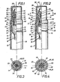
- FIG. 1 shows a section 10 of a container 10 for a liquid application medium.
- the container 10 consists bs pw. Of aluminum sheet and has a threaded neck 12 which defines the feed opening 14 through which the liquid coating medium is filled into the container 10.
- the housing 16 In the filling opening 14 of the container 10, the housing 16 of a valve known per se is inserted.
- the housing 16 has openings 18 through which the interior 20 of the container 10 is fluidly connected to the filling opening 14.
- a mouthpiece 22 Connected to the container 10 is a mouthpiece 22 which, for example, consists of an impact and scratch-resistant plastic.
- the mouthpiece 22 has a section 24 with an internal thread 26 which corresponds to the thread of the screw attachment 12.
- the mouthpiece 22 is screwed with the section 24 onto the screw set 12 in such a way that the housing 16 with its circumferential flange 28 is fixed axially immovably between the screw attachment 12 and the mouthpiece 22.
- the outer contour of the mouthpiece 22 and the inner contour of a closure cap 30 correspond to one another, so that the closure cap 30 can be pushed onto the mouthpiece 22 to complete the applicator.
- the sleeve-shaped mouthpiece 22 has a central hole 32 in which an application member 34 is fastened.
- the application member 34 has a central cavity 36 and an outlet opening 38, which is sealed by a ball 40 is.
- the central cavity 36 of the application member 34 has a ball receiving space 42, an adjoining section 44 with a narrowed cross section and a main cavity 46 adjoining the section 44 and facing the container 10.
- a spring element 48 is arranged, which has a rod-shaped section 50 and a holding body 52.
- the holding body 52 is arranged on the second end section of the rod-shaped section 50 which faces the container 10.
- the first end section of the rod-shaped, resiliently bulging section 50 is formed with an extension 54, with which the rod-shaped section 50 bears against the ball 40.
- the extension 54 reduces the surface pressure with which the ball 40 presses against the rod-shaped section 50 of the spring element 48 during use of the application device. so that the wear of the first end portion of the rod-shaped portion 50 is reduced.
- the expansion 54 of the ball receiving space 42 is reduced, whereby the capillary action in the ball receiving space 42 is improved.
- the section 44 with a narrowed cross-section is formed with recesses 56, which are designed to be radial to the longitudinal center line 58 of the applicator.
- the slot-shaped recesses 56 and the annular space between the rod-shaped section 50 and the section 44 with a narrow cross-section have dimensions such that they form a capillary space for the application medium located in the container 10, such as the ball receiving space 42.
- the ball receiving space 42 is fluidly connected to the main cavity 46 of the central cavity 36 of the application member 34.
- the spring element 48 is connected to the application member 34 by means of transverse ribs 60 which protrude from the main body 52 of the spring element 48 in the radial direction.
- the main body 52 is with the transverse ribs 60 inserted into the main cavity 46, the transverse ribs 60 being clamped on the inner wall 62 of the main cavity 46 with an interference fit.
- the main body 52 has dimensions in relation to the inner wall 62 of the main cavity 46 such that the tubular space between the application member 34 and the main body 52 of the spring element 48 also forms a capillary space.
- the cap 30 is removed from the mouthpiece 22 and the applicator with the ball 40 is pressed against a base, so that the ball 40 is moved a small distance towards the container 10.
- the rod-shaped section 50 of the spring element 48 is bulged out laterally from the position aligned with the central longitudinal axis 58, because the main body 52 of the spring element 48 is arranged so as to be axially immovable with respect to the application member 34.
- the rod-shaped section 50 of the spring element 48 is mechanically relieved, whereby the rod-shaped section 50 returns to the drawn stretched position and presses the ball 40 again against the outlet opening 38, so that the outlet opening 38 passes through the ball 40 is tightly closed again.
- the reference numeral 64 denotes a circumferential approach which is closely shaped to the application member 34 and by means of which the application organ 34 bears against the mouthpiece 22.
- Fig. 2 shows a second embodiment of the application device, the container 10 for the liquid application medium is shown only in sections.
- the reference number 22 in this figure denotes a mouthpiece which has a section 24 with an internal thread and which is screwed with this section 24 onto a threaded extension 12 of the container.
- a closure cap 30 is placed on the mouthpiece 22.
- the filling opening 14 of the container 10 defined by the threaded shoulder 12 of the container 10 is closed by a valve 66 known per se, the housing 16 of which is fixed axially immovably with a circumferential shoulder 28 between the threaded shoulder 12 of the container 10 and the mouthpiece 22.
- the reference numeral 68 in this figure denotes a valve actuating element with the aid of which the valve 66 can be opened in order to establish a fluidic connection between the interior 20 of the container 10 through the openings 18 in the valve housing 16 to the central cavity 36 in the application member 34.
- valve actuating element 68 is actuated only with the applicator 34 without the spring element 48 executing an axial movement relative to the actuating member 34, it is necessary that the end face 72 of the main body 52 does not have the annular base 74 of the Order organ 34 protrudes in the direction of the container 10.
- Reference number 54 again denotes the expansion of the rod-shaped section 50 against which the ball 40 closing the outlet opening 38 bears.
- the reference numeral 56 denotes recesses which extend in the longitudinal direction of section 44 with a narrowed cross section and fluidly connect the ball receiving space 42 to the main ear space 46.
- the liquid application medium is also stored in this capillary space when the application device is brought into the upright position shown after use. This will dry out the capillary space mentioned avoided, so that when the application device is used again, the amount of liquid application medium stored in the capillary space is immediately available for application to a support.
- the ball 40 can be a metal or plastic ball, the surface of which can have a certain defined roughness. A slightly roughened ball surface rotates the ball while the applicator is in use, thereby promoting the delivery of the liquid application medium from the capillary space through the outlet opening 36.
- FIG. 3 shows in cross section the rod-shaped section 50 of the spring element 48 and the section 44 of the application member 34 with a narrowed cross section. From this figure, the recesses 56 are also clearly visible, which are aligned radially with respect to the rod-shaped section 50 of the spring element 48 and are evenly distributed. With the reference number 30 the cap of the applicator is designated.
- Fig. 4 shows a cross section through the holding body 52 of the spring element 48. From the holding body 52 there are in the radial direction transverse ribs 60 with which the holding body 52 is clamped in the main cavity 46 of the central cavity 36 of the application member 34.
- Reference number 22 denotes the mouth bucket, in the central hole 32 of which the application member 34 can be moved in the axial direction, ie into the plane of the drawing or out of the plane of the drawing.
- the reference number 30 also designates the closure cap in this figure.
- the pin-shaped section 50 ends in front of the ball 40 without touching the ball 40.
- the pin-shaped section 50 naturally does not need to have an extension 54 either.
- the pin-shaped section 50 is surrounded there by a helical spring which resiliently abuts the ball 40 with its one end section.
- the second end portion of the coil spring abuts the main body 52 of the central body 48.
- the central body 48 is not a spring element, but rather a body with the aid of which the capillary space 36 is precisely delimited on the one hand.
- the capillary space 36 is limited by the inner contour of the central cavity of the application member 34.
- the central cavity can also have a ball receiving space 42, a section 44 with a narrow cross section and a main cavity 46.
- the last-mentioned design of the application device results in an even more uniform delivery of the liquid application medium through the capillary space 36 and through the outlet opening 38 than in the case of a spring element 48 bulging on one side with a rod-shaped section 50 resting against the ball 40. Since the spring element in Shape of a coil spring is attached to the rod-shaped section 50 of the central body 48 before the central body 48 is fastened in the central cavity 36 of the application member 34, the assembly of the application device of the latter type according to the invention is also easier than with a known application device of the generic type Art.
Landscapes
- Engineering & Computer Science (AREA)
- Mechanical Engineering (AREA)
- Pens And Brushes (AREA)
- Coating Apparatus (AREA)
- Closures For Containers (AREA)
Priority Applications (1)
| Application Number | Priority Date | Filing Date | Title |
|---|---|---|---|
| AT87106937T ATE65463T1 (de) | 1986-05-13 | 1987-05-13 | Auftragsgeraet. |
Applications Claiming Priority (2)
| Application Number | Priority Date | Filing Date | Title |
|---|---|---|---|
| DE19863616116 DE3616116A1 (de) | 1986-05-13 | 1986-05-13 | Auftragsgeraet |
| DE3616116 | 1986-05-13 |
Publications (2)
| Publication Number | Publication Date |
|---|---|
| EP0249042A1 true EP0249042A1 (fr) | 1987-12-16 |
| EP0249042B1 EP0249042B1 (fr) | 1991-07-24 |
Family
ID=6300744
Family Applications (1)
| Application Number | Title | Priority Date | Filing Date |
|---|---|---|---|
| EP87106937A Expired - Lifetime EP0249042B1 (fr) | 1986-05-13 | 1987-05-13 | Réservoir distributeur |
Country Status (5)
| Country | Link |
|---|---|
| US (1) | US4993860A (fr) |
| EP (1) | EP0249042B1 (fr) |
| JP (1) | JPS6328471A (fr) |
| AT (1) | ATE65463T1 (fr) |
| DE (1) | DE3616116A1 (fr) |
Cited By (2)
| Publication number | Priority date | Publication date | Assignee | Title |
|---|---|---|---|---|
| EP0548600A1 (fr) * | 1991-12-11 | 1993-06-30 | Sailor Pen Co., Ltd. | Applicateur |
| KR20010100147A (ko) * | 2001-10-15 | 2001-11-14 | 한재만 | 액상물 도포용기 |
Families Citing this family (18)
| Publication number | Priority date | Publication date | Assignee | Title |
|---|---|---|---|---|
| US5151302A (en) * | 1991-06-18 | 1992-09-29 | Carole L. Kent | Method for maintaining the integrity of hosiery |
| KR930021412A (ko) * | 1992-04-02 | 1993-11-22 | 이시카와 히데아키 | 수정기 |
| IT228562Y1 (it) * | 1992-06-26 | 1998-04-27 | Mira Lanza S P A Ora S R L | Dosatore-erogatore per detersivo liquido per macchine lavatrici. |
| US5526960A (en) * | 1994-12-14 | 1996-06-18 | Fragrance Systems International, Inc. | Perfume dispenser with replaceable cartridges |
| US5586694A (en) * | 1994-12-14 | 1996-12-24 | Fragrance Systems International, Inc. | Perfume applicator with replaceable cartridges |
| US5988922A (en) * | 1995-06-01 | 1999-11-23 | The Gillette Company | Valve for correction fluid dispenser |
| KR100347163B1 (ko) * | 1995-12-06 | 2003-03-31 | 티에무시가켄 가부시키가이샤 | 펜형약제도포구 |
| DE19648630C2 (de) | 1996-11-12 | 1999-01-07 | Rotring Int Gmbh | Auftraggerät |
| DE19730454C2 (de) * | 1997-07-16 | 2002-01-03 | Lothar Sommer | Schreib-, Mal-, Zeichen-, Markier- oder Auftragsgerät |
| USD438469S1 (en) | 1998-11-09 | 2001-03-06 | Fragrance Systems International, Inc. | Dual fragrance bottle |
| USD425412S (en) * | 1998-11-09 | 2000-05-23 | Fragrance Systems International, Inc. | Domed dual fragrance bottle |
| US6276853B1 (en) | 1999-04-14 | 2001-08-21 | Fragrance Systems International Inc. | Axially aligned, commonly joined dual dispensers |
| US7377707B2 (en) | 2000-02-29 | 2008-05-27 | Breidenbach Diane C | Lip product applicator |
| US20040234321A1 (en) | 2001-04-25 | 2004-11-25 | Breidenbach Diane C. | Dual cosmetic container |
| USD558927S1 (en) | 2000-02-29 | 2008-01-01 | Diane Breidenbach | Clear lip applicator |
| US6488427B1 (en) | 2000-02-29 | 2002-12-03 | Diane C. Breidenbach | Cosmetic applicator |
| USD558926S1 (en) | 2000-02-29 | 2008-01-01 | Diane Breidenbach | Lip applicator |
| US9352350B2 (en) | 2012-07-03 | 2016-05-31 | Arminak & Associates, Llc | Roll-on applicator |
Citations (5)
| Publication number | Priority date | Publication date | Assignee | Title |
|---|---|---|---|---|
| GB922529A (en) * | 1959-01-23 | 1963-04-03 | Roland Graf Von Faber Castell | Ball-point pens |
| FR1337124A (fr) * | 1962-10-25 | 1963-09-06 | David Kahn | Réservoir pour un instrument à écrire |
| DE2115043A1 (de) * | 1971-03-27 | 1972-10-05 | Gebr. Schmidt, Fabrik für Feinmechanik, 7742 St. Georgen | Tintenkugelschreiber |
| DE2723032A1 (de) * | 1976-07-02 | 1978-01-12 | Andrea Dazzi | Kugelschreiberspitze, insbesondere fuer tinten niedriger viskositaet |
| EP0164644A2 (fr) * | 1984-06-15 | 1985-12-18 | Schwan-STABILO Schwanhäusser GmbH & Co. | Appareil pour appliquer des fluides cosmétiques |
Family Cites Families (22)
| Publication number | Priority date | Publication date | Assignee | Title |
|---|---|---|---|---|
| US1194347A (en) * | 1916-08-15 | axileh | ||
| US1714030A (en) * | 1928-07-13 | 1929-05-21 | Boeuf Frank Le | Dispensing device |
| US2122580A (en) * | 1936-09-16 | 1938-07-05 | John T Morris | Perfume applicator |
| US2228540A (en) * | 1940-10-26 | 1941-01-14 | Fred A Sturm | Marking implement |
| US2613382A (en) * | 1946-09-09 | 1952-10-14 | Louis L Patterson | Liquid dispensing device having a globular combined applicator and outlet valve |
| DE816965C (de) * | 1949-10-21 | 1951-10-15 | Montblanc Simplo Gmbh | Schreibkugel-Fuellhalter |
| FR1136563A (fr) * | 1955-11-23 | 1957-05-15 | Prod Chim Solor Soc D | Obturateur verseur pour l'épandage des substances fluides et semi-fluides |
| DE1209912B (de) * | 1958-03-28 | 1966-01-27 | Faber Castell A W | Kugelschreiber mit gegen eine Rueckstellkraft nach innen verschiebbarer Kugel |
| DE1270447B (de) * | 1961-10-28 | 1968-06-12 | Julius Lindenmeyer Dr Ing | Kugelschreiber |
| JPS4917860B1 (fr) * | 1964-10-08 | 1974-05-04 | ||
| AT248282B (de) * | 1965-02-19 | 1966-07-25 | Schrauben Schmiedewaaren Und B | Kugelschreiber für leichtflüssige Tinten |
| US3379490A (en) * | 1965-11-01 | 1968-04-23 | Schwartzman Gilbert | Narrow line applicator |
| US3537801A (en) * | 1967-12-19 | 1970-11-03 | Francisco Barcelloni Corte | Ball point for writing instruments |
| FR1559482A (fr) * | 1968-03-30 | 1969-03-07 | ||
| JPS5025628U (fr) * | 1973-06-29 | 1975-03-24 | ||
| US3902815A (en) * | 1974-04-01 | 1975-09-02 | Liquid Paper Corp | Positive displacement dispenser |
| JPS5113912U (fr) * | 1974-07-16 | 1976-01-31 | ||
| JPS5412410Y2 (fr) * | 1975-12-10 | 1979-05-31 | ||
| DE2743888A1 (de) * | 1977-09-29 | 1979-04-05 | Pilot Ink Co Ltd | Kugelschreiber |
| US4281779A (en) * | 1978-09-05 | 1981-08-04 | Shepard John S | Dispensing valve |
| GB2073676B (en) * | 1980-03-28 | 1983-10-05 | Pentel Kk | Socket for a ball point |
| US4572691A (en) * | 1984-07-02 | 1986-02-25 | Minnesota Mining And Manufacturing Company | Pen-like instrument for applying correction fluid |
-
1986
- 1986-05-13 DE DE19863616116 patent/DE3616116A1/de active Granted
-
1987
- 1987-05-12 US US07/049,777 patent/US4993860A/en not_active Expired - Fee Related
- 1987-05-13 JP JP62114897A patent/JPS6328471A/ja active Pending
- 1987-05-13 EP EP87106937A patent/EP0249042B1/fr not_active Expired - Lifetime
- 1987-05-13 AT AT87106937T patent/ATE65463T1/de not_active IP Right Cessation
Patent Citations (5)
| Publication number | Priority date | Publication date | Assignee | Title |
|---|---|---|---|---|
| GB922529A (en) * | 1959-01-23 | 1963-04-03 | Roland Graf Von Faber Castell | Ball-point pens |
| FR1337124A (fr) * | 1962-10-25 | 1963-09-06 | David Kahn | Réservoir pour un instrument à écrire |
| DE2115043A1 (de) * | 1971-03-27 | 1972-10-05 | Gebr. Schmidt, Fabrik für Feinmechanik, 7742 St. Georgen | Tintenkugelschreiber |
| DE2723032A1 (de) * | 1976-07-02 | 1978-01-12 | Andrea Dazzi | Kugelschreiberspitze, insbesondere fuer tinten niedriger viskositaet |
| EP0164644A2 (fr) * | 1984-06-15 | 1985-12-18 | Schwan-STABILO Schwanhäusser GmbH & Co. | Appareil pour appliquer des fluides cosmétiques |
Cited By (2)
| Publication number | Priority date | Publication date | Assignee | Title |
|---|---|---|---|---|
| EP0548600A1 (fr) * | 1991-12-11 | 1993-06-30 | Sailor Pen Co., Ltd. | Applicateur |
| KR20010100147A (ko) * | 2001-10-15 | 2001-11-14 | 한재만 | 액상물 도포용기 |
Also Published As
| Publication number | Publication date |
|---|---|
| ATE65463T1 (de) | 1991-08-15 |
| DE3616116A1 (de) | 1987-11-19 |
| US4993860A (en) | 1991-02-19 |
| JPS6328471A (ja) | 1988-02-06 |
| EP0249042B1 (fr) | 1991-07-24 |
| DE3616116C2 (fr) | 1988-12-08 |
Similar Documents
| Publication | Publication Date | Title |
|---|---|---|
| EP0249042A1 (fr) | Réservoir distributeur | |
| EP0516636B1 (fr) | Distributeur pour milieux | |
| EP0727191A2 (fr) | Récipient pour distribuer des masses dentaires | |
| EP0368062A1 (fr) | Distributeur de produits pâteux | |
| DE9400524U1 (de) | Vorrichtung zum Entleeren eines Schlauchbeutels | |
| DE2641171B2 (de) | Schreibgerät | |
| EP1986789A2 (fr) | Dispositif de dosage dote d'un dispositif de pompage actionne a la main | |
| EP0111089B1 (fr) | Récipient sous pression pour gaz, liquides, produits pâteux ou similaires | |
| DE2417376A1 (de) | Mischventil | |
| DE602004013033T2 (de) | Ventil und abgabeeinrichtung mit einem solchen ventil | |
| DE19730454C2 (de) | Schreib-, Mal-, Zeichen-, Markier- oder Auftragsgerät | |
| EP0743830A1 (fr) | Systeme d'application | |
| DE1291257B (de) | Schreibgeraet | |
| DE3916670C2 (fr) | ||
| DE10201318B4 (de) | Fülleinrichtung mit lateralen Füllfenstern für ein Schreibgerät | |
| DE3605506A1 (de) | Schreibgeraet | |
| EP0255060A2 (fr) | Pistolet pour la projection de mousses plastiques, en particulier de mousse de polyuréthane à un seul composant | |
| DE3529712C1 (de) | Spender für einen Reinigungsstoff mit einer Quetschflasche | |
| EP0240692A1 (fr) | Applicateur | |
| DE3319197C2 (de) | Vorrichtung nach Art eines Markierungsstiftes, insbesondere zum Auftragen eines zähflüssigen Klebers | |
| DE3019924C2 (de) | Absperreinrichtung für Flüssigkeiten | |
| DE9412712U1 (de) | Dosierverschluß | |
| DE387740C (de) | Fluessigkeitsverteiler | |
| DE1400715C (de) | Befestigung eines Tauchrohres am Ventilgehäuse eines Sprühbehälters | |
| DE2104510C3 (de) | Dosierventil |
Legal Events
| Date | Code | Title | Description |
|---|---|---|---|
| PUAI | Public reference made under article 153(3) epc to a published international application that has entered the european phase |
Free format text: ORIGINAL CODE: 0009012 |
|
| AK | Designated contracting states |
Kind code of ref document: A1 Designated state(s): AT BE CH DE ES FR GB GR IT LI LU NL SE |
|
| RBV | Designated contracting states (corrected) |
Designated state(s): AT BE CH ES FR GB GR IT LI LU NL SE |
|
| 17P | Request for examination filed |
Effective date: 19880419 |
|
| 17Q | First examination report despatched |
Effective date: 19890609 |
|
| GRAA | (expected) grant |
Free format text: ORIGINAL CODE: 0009210 |
|
| AK | Designated contracting states |
Kind code of ref document: B1 Designated state(s): AT BE CH ES FR GB GR IT LI LU NL SE |
|
| PG25 | Lapsed in a contracting state [announced via postgrant information from national office to epo] |
Ref country code: IT Free format text: LAPSE BECAUSE OF FAILURE TO SUBMIT A TRANSLATION OF THE DESCRIPTION OR TO PAY THE FEE WITHIN THE PRESCRIBED TIME-LIMIT;WARNING: LAPSES OF ITALIAN PATENTS WITH EFFECTIVE DATE BEFORE 2007 MAY HAVE OCCURRED AT ANY TIME BEFORE 2007. THE CORRECT EFFECTIVE DATE MAY BE DIFFERENT FROM THE ONE RECORDED. Effective date: 19910724 Ref country code: SE Effective date: 19910724 Ref country code: NL Effective date: 19910724 Ref country code: GR Free format text: LAPSE BECAUSE OF FAILURE TO SUBMIT A TRANSLATION OF THE DESCRIPTION OR TO PAY THE FEE WITHIN THE PRESCRIBED TIME-LIMIT Effective date: 19910724 |
|
| REF | Corresponds to: |
Ref document number: 65463 Country of ref document: AT Date of ref document: 19910815 Kind code of ref document: T |
|
| GBT | Gb: translation of ep patent filed (gb section 77(6)(a)/1977) | ||
| ET | Fr: translation filed | ||
| PG25 | Lapsed in a contracting state [announced via postgrant information from national office to epo] |
Ref country code: ES Free format text: LAPSE BECAUSE OF FAILURE TO SUBMIT A TRANSLATION OF THE DESCRIPTION OR TO PAY THE FEE WITHIN THE PRESCRIBED TIME-LIMIT Effective date: 19911104 |
|
| NLV1 | Nl: lapsed or annulled due to failure to fulfill the requirements of art. 29p and 29m of the patents act | ||
| PLBE | No opposition filed within time limit |
Free format text: ORIGINAL CODE: 0009261 |
|
| STAA | Information on the status of an ep patent application or granted ep patent |
Free format text: STATUS: NO OPPOSITION FILED WITHIN TIME LIMIT |
|
| 26N | No opposition filed | ||
| EPTA | Lu: last paid annual fee | ||
| PGFP | Annual fee paid to national office [announced via postgrant information from national office to epo] |
Ref country code: CH Payment date: 19950131 Year of fee payment: 9 |
|
| PGFP | Annual fee paid to national office [announced via postgrant information from national office to epo] |
Ref country code: BE Payment date: 19950222 Year of fee payment: 9 |
|
| PGFP | Annual fee paid to national office [announced via postgrant information from national office to epo] |
Ref country code: FR Payment date: 19950224 Year of fee payment: 9 |
|
| PGFP | Annual fee paid to national office [announced via postgrant information from national office to epo] |
Ref country code: LU Payment date: 19950301 Year of fee payment: 9 |
|
| PGFP | Annual fee paid to national office [announced via postgrant information from national office to epo] |
Ref country code: AT Payment date: 19950310 Year of fee payment: 9 |
|
| PGFP | Annual fee paid to national office [announced via postgrant information from national office to epo] |
Ref country code: GB Payment date: 19950502 Year of fee payment: 9 |
|
| PG25 | Lapsed in a contracting state [announced via postgrant information from national office to epo] |
Ref country code: AT Effective date: 19960513 Ref country code: GB Effective date: 19960513 Ref country code: LU Free format text: LAPSE BECAUSE OF NON-PAYMENT OF DUE FEES Effective date: 19960513 |
|
| PG25 | Lapsed in a contracting state [announced via postgrant information from national office to epo] |
Ref country code: LI Effective date: 19960531 Ref country code: CH Effective date: 19960531 Ref country code: BE Effective date: 19960531 |
|
| BERE | Be: lapsed |
Owner name: EDDING A.G. Effective date: 19960531 |
|
| GBPC | Gb: european patent ceased through non-payment of renewal fee |
Effective date: 19960513 |
|
| REG | Reference to a national code |
Ref country code: CH Ref legal event code: PL |
|
| PG25 | Lapsed in a contracting state [announced via postgrant information from national office to epo] |
Ref country code: FR Effective date: 19970131 |
|
| REG | Reference to a national code |
Ref country code: FR Ref legal event code: ST |