EP0249068B1 - Verfahren und Vorrichtung zur Reinigung von schadstoffhaltigen Gasen - Google Patents
Verfahren und Vorrichtung zur Reinigung von schadstoffhaltigen Gasen Download PDFInfo
- Publication number
- EP0249068B1 EP0249068B1 EP87107355A EP87107355A EP0249068B1 EP 0249068 B1 EP0249068 B1 EP 0249068B1 EP 87107355 A EP87107355 A EP 87107355A EP 87107355 A EP87107355 A EP 87107355A EP 0249068 B1 EP0249068 B1 EP 0249068B1
- Authority
- EP
- European Patent Office
- Prior art keywords
- spiral
- spiral surface
- absorption liquid
- rotating axle
- gas
- Prior art date
- Legal status (The legal status is an assumption and is not a legal conclusion. Google has not performed a legal analysis and makes no representation as to the accuracy of the status listed.)
- Expired - Lifetime
Links
- 239000007789 gas Substances 0.000 title claims abstract description 34
- 238000010521 absorption reaction Methods 0.000 claims abstract description 37
- 239000007788 liquid Substances 0.000 claims abstract description 36
- 239000003344 environmental pollutant Substances 0.000 claims abstract description 10
- 231100000719 pollutant Toxicity 0.000 claims abstract description 10
- MWUXSHHQAYIFBG-UHFFFAOYSA-N Nitric oxide Chemical compound O=[N] MWUXSHHQAYIFBG-UHFFFAOYSA-N 0.000 claims abstract description 9
- QGZKDVFQNNGYKY-UHFFFAOYSA-N Ammonia Chemical compound N QGZKDVFQNNGYKY-UHFFFAOYSA-N 0.000 claims abstract description 6
- JUJWROOIHBZHMG-UHFFFAOYSA-N Pyridine Chemical compound C1=CC=NC=C1 JUJWROOIHBZHMG-UHFFFAOYSA-N 0.000 claims abstract description 6
- RAHZWNYVWXNFOC-UHFFFAOYSA-N Sulphur dioxide Chemical compound O=S=O RAHZWNYVWXNFOC-UHFFFAOYSA-N 0.000 claims abstract description 6
- 238000000746 purification Methods 0.000 claims abstract description 4
- ZAMOUSCENKQFHK-UHFFFAOYSA-N Chlorine atom Chemical compound [Cl] ZAMOUSCENKQFHK-UHFFFAOYSA-N 0.000 claims abstract description 3
- RWSOTUBLDIXVET-UHFFFAOYSA-N Dihydrogen sulfide Chemical compound S RWSOTUBLDIXVET-UHFFFAOYSA-N 0.000 claims abstract description 3
- PXGOKWXKJXAPGV-UHFFFAOYSA-N Fluorine Chemical compound FF PXGOKWXKJXAPGV-UHFFFAOYSA-N 0.000 claims abstract description 3
- 150000001412 amines Chemical class 0.000 claims abstract description 3
- 229910021529 ammonia Inorganic materials 0.000 claims abstract description 3
- 239000000460 chlorine Substances 0.000 claims abstract description 3
- 229910052801 chlorine Inorganic materials 0.000 claims abstract description 3
- 239000011737 fluorine Substances 0.000 claims abstract description 3
- 229910052731 fluorine Inorganic materials 0.000 claims abstract description 3
- UMJSCPRVCHMLSP-UHFFFAOYSA-N pyridine Natural products COC1=CC=CN=C1 UMJSCPRVCHMLSP-UHFFFAOYSA-N 0.000 claims abstract description 3
- 239000002904 solvent Substances 0.000 claims abstract description 3
- VEXZGXHMUGYJMC-UHFFFAOYSA-M Chloride anion Chemical compound [Cl-] VEXZGXHMUGYJMC-UHFFFAOYSA-M 0.000 claims abstract 2
- 235000010269 sulphur dioxide Nutrition 0.000 claims abstract 2
- 239000004291 sulphur dioxide Substances 0.000 claims abstract 2
- 239000002184 metal Substances 0.000 claims description 6
- 238000004804 winding Methods 0.000 claims description 3
- 125000006850 spacer group Chemical group 0.000 claims description 2
- YXFVVABEGXRONW-UHFFFAOYSA-N Toluene Chemical compound CC1=CC=CC=C1 YXFVVABEGXRONW-UHFFFAOYSA-N 0.000 claims 3
- 208000032912 Local swelling Diseases 0.000 claims 1
- 239000000203 mixture Substances 0.000 claims 1
- 229920002545 silicone oil Polymers 0.000 claims 1
- XLYOFNOQVPJJNP-UHFFFAOYSA-N water Substances O XLYOFNOQVPJJNP-UHFFFAOYSA-N 0.000 claims 1
- 238000004140 cleaning Methods 0.000 description 8
- 239000010408 film Substances 0.000 description 2
- 239000007921 spray Substances 0.000 description 2
- 150000001805 chlorine compounds Chemical class 0.000 description 1
- 238000011109 contamination Methods 0.000 description 1
- 238000011161 development Methods 0.000 description 1
- 230000018109 developmental process Effects 0.000 description 1
- 229910000037 hydrogen sulfide Inorganic materials 0.000 description 1
- 230000002093 peripheral effect Effects 0.000 description 1
- 238000003756 stirring Methods 0.000 description 1
- 239000010409 thin film Substances 0.000 description 1
Images
Classifications
-
- B—PERFORMING OPERATIONS; TRANSPORTING
- B01—PHYSICAL OR CHEMICAL PROCESSES OR APPARATUS IN GENERAL
- B01D—SEPARATION
- B01D47/00—Separating dispersed particles from gases, air or vapours by liquid as separating agent
- B01D47/16—Apparatus having rotary means, other than rotatable nozzles, for atomising the cleaning liquid
-
- B—PERFORMING OPERATIONS; TRANSPORTING
- B01—PHYSICAL OR CHEMICAL PROCESSES OR APPARATUS IN GENERAL
- B01D—SEPARATION
- B01D53/00—Separation of gases or vapours; Recovering vapours of volatile solvents from gases; Chemical or biological purification of waste gases, e.g. engine exhaust gases, smoke, fumes, flue gases, aerosols
- B01D53/14—Separation of gases or vapours; Recovering vapours of volatile solvents from gases; Chemical or biological purification of waste gases, e.g. engine exhaust gases, smoke, fumes, flue gases, aerosols by absorption
- B01D53/18—Absorbing units; Liquid distributors therefor
-
- B—PERFORMING OPERATIONS; TRANSPORTING
- B01—PHYSICAL OR CHEMICAL PROCESSES OR APPARATUS IN GENERAL
- B01D—SEPARATION
- B01D53/00—Separation of gases or vapours; Recovering vapours of volatile solvents from gases; Chemical or biological purification of waste gases, e.g. engine exhaust gases, smoke, fumes, flue gases, aerosols
- B01D53/34—Chemical or biological purification of waste gases
Definitions
- the invention relates to a device for cleaning pollutant-containing gases, in particular sulfur dioxide, fluorine, chlorine, chlorides, hydrogen sulfide, ammonia, amines, pyridine, nitrogen oxides and / or gases containing solvent vapors, in particular air, with a rotating arrangement in the flow of the gas to be cleaned Spiral surface, the absorption liquid can be supplied in the region of the axis of rotation.
- pollutant-containing gases in particular sulfur dioxide, fluorine, chlorine, chlorides, hydrogen sulfide, ammonia, amines, pyridine, nitrogen oxides and / or gases containing solvent vapors, in particular air
- Such a device is known from DE-B 1 099 500.
- the introduction of the gas to be cleaned and the discharge of the cleaned gas take place tangentially to the rotationally driven spiral surface, which is defined by a plurality of sheets which extend between an inner and outer ring surface and are distributed uniformly over the circumference and are each spirally curved.
- the rotationally driven spiral surface which is defined by a plurality of sheets which extend between an inner and outer ring surface and are distributed uniformly over the circumference and are each spirally curved.
- d. H Within the inner ring surface, radially directed spray heads are arranged, through which absorption liquid can be fed to the spirally bent metal sheets. Due to the described type of spiral surface structure and the described type of gas inlet and outlet, the known device is built relatively space-intensive.
- the situation of the device according to DE-B 1 017 597 is very similar.
- the device described there differs from the device according to DE-B 1 099 500 essentially only in that instead of central distributor nozzles, a transport screw for the supply of absorption liquid is provided.
- the present invention has for its object to provide a device of the type mentioned, which is characterized by a compact design with a comparatively large absorption area, while at the same time it should be ensured that the pressure drop of the gas passed through the device is minimal.
- the axially parallel flow through the spiral surface Due to the axially parallel flow through the spiral surface, it can be placed within a tubular housing, with the result of a correspondingly compact and arbitrarily expandable design, without the effective spiral surface being lost.
- the axially parallel flow through the spiral surface also has the advantage of a high concentration gradient between gas and absorption liquid in the area of the gas inlet.
- the pressure drop of the gas passed through the device according to the invention is minimal, since the gas to be cleaned can flow through the device practically without being deflected.
- the absorption liquid can be distributed very specifically on the spiral surface, i. H. practically lossless.
- the absorption surface supplied is distributed approximately uniformly progressively from radially inside to radially outside.
- the supply of the absorption liquid according to the invention allows a minimal consumption per unit of time. with the same high absorbency or gas purification level.
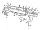
- the embodiment shown comprises a continuous spiral surface 10, which is fastened within a cylindrical channel or housing 12 to a rotationally driven axis of rotation 14.
- the axis of rotation 14 is driven by a drive motor, preferably an electric motor, the speed of rotation being preferably variable.
- the axis of rotation 14 is provided in the fastening area of the spiral surface 10 with radial openings for the exit of an absorption liquid.
- the absorption liquid is thus fed centrally to the spiral surface 10 in the area of the axis of rotation 14. Due to the rotational movement (arrow 40) of the spiral surface 10, the absorption liquid is distributed approximately uniformly and progressively from the inside to the spiral surface 10 (arrows 18), so that a thin film of absorption liquid is formed on the spiral surface 10.
- a collecting trough 20 is arranged below the spiral surface 10, which is defined by a sheet metal strip which is bent continuously in a spiral. In the embodiment shown, this forms part of the cylindrical housing or channel 12.
- the collecting trough 20 forms a collecting basin for pollutant-enriched absorption liquid, which drips off the rotatingly driven spiral surface 10.
- the pollutant-containing absorption liquid is pumped from the collecting trough 20 to a cleaning device 22, specifically by means of a pump 24.
- a line 26 leads from the cleaning device to a collecting vessel for the separated pollutants.
- the absorption liquid cleaned in the cleaning device 22 is finally returned via a line 28 to the hollow axis of rotation 14. In the area of the spiral surface 10, the cleaned absorption liquid can then exit radially again and progressively wet the spiral surface 10 from the inside to the outside.
- the gas to be cleaned flows through the channel or the cylindrical housing 12 in the direction of the axis of rotation 14, namely in contact the drawing from right to left.
- the gas is cleaned of pollutants, the type of absorption liquid used depending on the pollutants to be absorbed.
- the degree of cleaning can be optimally adapted to the degree of contamination by varying the circulation of the absorption liquid (speed of the absorption liquid circuit), the gradient of the spiral surface 10 and its rotational speed.
- An “absorption liquid curtain” can also be provided on the gas inlet side 30.
- an absorption spray device is provided there.
- spacers can be arranged between them, preferably distributed uniformly over the circumference and the length of the spiral surface 10 or in the form of helical springs or helices extending in the spiral direction.
- Another or additional possibility of keeping the distance between the individual spiral turns is to provide the spiral sheet with deformations that increase stability, such as curvatures or the like.
- the rotary drive of the spiral surface 10 takes place via the rotationally driven axis of rotation 14, on which the motor 16 acts.
- the spiral surface 10 it is also conceivable to provide the spiral surface 10 with guide vanes or to couple it with a type of propeller such that the rotation of the spiral surface 10 is brought about by the flow of the gas to be cleaned.
- the spiral surface can be provided with perforations, slits or the like, through which absorption liquid drips transversely to the gas flow. This creates additional contact area or absorption area. Furthermore, a faster distribution of the absorption liquid from the inside to the outside is achieved. Finally, liquid drops hitting an underlying liquid film stir the latter, thereby achieving better convection.
- the pressure drop of the gas passed through the device described is minimal, since the gas to be cleaned can be passed through the device practically without being deflected.
- the radial openings of the hollow axis of rotation 14 in the region of the spiral surface 10 are arranged in such a way that the emerging absorption liquid reaches the radially inner side of the spiral surface 10 and spreads along it radially outwards, forming a thin absorption liquid film. This moves on the inside of the spiral surface 10 from the inside to the outside. The absorption liquid is thrown off at the peripheral opening 34 of the spiral surface 10 and collected in the collecting trough 20. From there, the absorption liquid, which now contains pollutants, reaches the cleaning device 22 in the manner described above.
- the spiral surface can also be arranged upright.
Landscapes
- Chemical & Material Sciences (AREA)
- Engineering & Computer Science (AREA)
- Chemical Kinetics & Catalysis (AREA)
- Analytical Chemistry (AREA)
- General Chemical & Material Sciences (AREA)
- Oil, Petroleum & Natural Gas (AREA)
- Health & Medical Sciences (AREA)
- Biomedical Technology (AREA)
- Environmental & Geological Engineering (AREA)
- Treating Waste Gases (AREA)
- Gas Separation By Absorption (AREA)
Description
- Die Erfindung betrifft eine Vorrichtung zur Reinigung von schadstoffhaltigen Gasen, insbesondere Schwefeldioxid, Fluor, Chlor, Chloride, Schwefelwasserstoff, Ammoniak, Amine, Pyridin, Stickoxide und/oder Lösungsmitteldämpfe enthaltenden Gasen, insbesondere Luft, mit einer in der Strömung des zu reinigenden Gases rotierend angeordneten Spiralfläche, der im Bereich der Drehachse Absorptionsflüssigkeit zuführbar ist.
- Eine derartige Vorrichtung ist aus der DE-B 1 099 500 bekannt.
- Bei der bekannten Vorrichtung erfolgt die Einleitung des zu reinigenden und Ableitung des gereinigten Gases jeweils tangential zur drehangetriebenen Spiralfläche, die durch eine Vielzahl von sich zwischen einer inneren und äußeren Ringfläche erstreckenden, gleichmäßig über den Umfang verteilt angeordneten, jeweils spiralartig gebogenen Blechen definiert ist. Im Bereich der Drehachse, d. h. innerhalb der inneren Ringfläche, sind radial gerichtete Verteilerbrausen angeordnet, durch die den spiralartig gebogenen Blechen Absorptionsflüssigkeit zuführbar ist. Durch die beschriebene Art des Spiralflächen-Aufbaus und durch die beschriebene Art der Gasein- und -ableitung ist die bekannte Vorrichtung relativ raumintensiv gebaut. Des weiteren ist durch die tangentiale Einleitung des zu reinigenden Gases derart, daß dieses auf die spiralartig gebogenen Bleche radial außen auftrifft, eine optimale Gasreinigung nicht gewährleistet, da im radial äußeren Bereich der spiralartig gebogenen Bleche die Absorptionsflüssigkeit zumindest teilweise schon verbraucht ist. Schließlich ist bei der bekannten Vorrichtung auch der Druckabfall des durch die Vorrichtung hindurchgeführten Gases relativ hoch aufgrund der notwendigen Gasumlenkungen.
- Ganz ähnlich verhält es sich bei der Vorrichtung nach der DE-B 1 017 597. Die dort beschriebene Vorrichtung unterscheidet sich von der Vorrichtung nach der DE-B 1 099 500 im wesentlichen nur dadurch, daß statt zentraler Verteilerdüsen eine Transportschnecke für die Zufuhr von Absorptionsflüssigkeit vorgesehen ist.
- Der vorliegenden Erfindung liegt die Aufgabe zugrunde, eine Vorrichtung der eingangs genannten Art zu schaffen, die sich durch eine kompakte Bauweise bei vergleichsweise großer Absorptionsfläche auszeichnet, wobei gleichzeitig darauf geachtet werden soll, daß der Druckabfall des durch die Vorrichtung hindurchgeführten Gases minimal ist.
- Diese Aufgabe wird durch die kennzeichnenden Merkmale des Patentanspruches 1 gelöst.
- Durch die achsparallele Durchströmung der Spiralfläche läßt sich diese innerhalb eines rohrförmigen Gehäuses plazieren mit der Folge einer entsprechend kompakten und beliebig vergrößerbaren Bauweise, ohne daß wirksame Spiralfläche verlorengeht. Die achsparallele Durchströmung der Spiralfläche hat des weiteren den Vorteil eines hohen Konzentrationsgefälles zwischen Gas und Absorptionsflüssigkeit im Bereich des Gaseintritts. Schließlich ist der Druckabfall des durch die erfindungsgemäße Vorrichtung hindurchgeführten Gases minimal, da das zu reinigende Gas praktisch ohne Umlenkung durch die Vorrichtung strömen kann.
- Durch die weitere Maßnahme, wonach die Drehachse durch einen Rohrabschnitt mit Öffnungen zum radialen Austritt der Absorptionsflüssigkeit gebildet ist, läßt sich die Absorptionsflüssigkeit sehr gezielt auf der Spiralfläche verteilen, d. h. praktisch verlustfrei. Durch die Drehbewegung der Spiralfläche wird die zugeführte Absorptionsfläche etwa gleichmäßig fortschreitend von radial innen nach radial außen verteilt. Die erfindungsgemäße Zufuhr der Absorptionsflüssigkeit erlaubt einen minimalen Verbrauch pro Zeiteinheit. bei unverändert hohem Absorptionsvermögen bzw. Gasreinigungsgrad.
- Vorteilhafte konstruktive Weiterbildungen der erfindungsgemäßen Vorrichtung sind in den Unteransprüchen beschrieben, wobei Anspruch 10 auf eine besonders vorteilhafte Verwendung der erfindungsgemäßen Vorrichtung hinweist.
- Nachstehend wird eine Ausführungsform der Erfindung anhand der beigefügten Zeichnung näher erläutert.
- Die dargestellte Ausführungsform umfaßt eine durchgehende Spiralfläche 10, die innerhalb eines zylindrischen Kanals bzw. Gehäuses 12 an einer rotierend angetriebenen Drehachse 14 befestigt ist. Die Drehachse 14 wird durch einen Antriebsmotor, vorzugsweise Elektromotor, angetrieben, wobei die Drehzahl vorzugsweise veränderbar ist.
- Die Drehachse 14 ist im Befestigungsbereich der Spiralfläche 10 mit radialen Öffnungen zum Austritt einer Absorptionsflüssigkeit versehen. Die Absorptionsflüssigkeit wird also zentral im Bereich der Drehachse 14 der Spiralfläche 10 zugeführt. Aufgrund der Rotationsbewegung (Pfeil 40) der Spiralfläche 10 wird die Absorptionsflüssigkeit etwa gleichmäßig und von innen nach außen fortschreitend auf der Spiralfläche 10 verteilt (Pfeile 18), so daß sich auf der Spiralfläche 10 ein dünner Absorptionsflüssigkeitsfilm ausbildet. Unterhalb der Spiralfläche 10, die durch ein durchgehend spiralförmig gebogenes Blechband definiert ist, ist eine Auffangwanne 20 angeordnet. Diese bildet bei der dargestellten Ausführungsform einen Teil des zylindrischen Gehäuses bzw. Kanals 12. Die Auffangwanne 20 bildet ein Sammelbecken für schadstoffangereicherte Absorptionsflüssigkeit, die von der rotierend angetriebenen Spiralfläche 10 abtropft.
- Von der Auffangwanne 20 wird die schadstoffhaltige Absorptionsflüssigkeit zu einer Reinigungsvorrichtung 22 gepumpt, und zwar mittels einer Pumpe 24. Von der Reinigungsvorrichtung führt eine Leitung 26 zu einem Sammelgefäß für die abgesonderten Schadstoffe. Die in der Reinigungsvorrichtung 22 gereinigte Absorptionsflüssigkeit wird schließlich über eine Leitung 28 wieder zur hohl ausgebildeten Drehachse 14 zurückgeführt. Im Bereich der Spiralfläche 10 kann dann die gereinigte Absorptionsflüssigkeit wieder radial austreten und die Spiralfläche 10 fortschreitend von innen nach außen benetzen.
- Das zu reinigende Gas strömt durch den Kanal bzw. das zylindrische Gehäuse 12 in Richtung der Drehachse 14 hindurch, und zwar in der anliegenden Zeichnung von rechts nach links. Im Bereich der mit Absorptionsflüssigkeit benetzten Spiralfläche 10 wird das Gas von Schadstoffen gereinigt, wobei die Art der verwendeten Absorptionsflüssigkeit von den zu absorbierenden Schadstoffen abhängt.
- Durch Variation der Umwälzung der Absorptionsflüssigkeit (Geschwindigkeit des Absorptionsflüssigkeits-Kreislaufes), der Steigung der Spiralfläche 10 sowie deren Rotationsgeschwindigkeit kann der Reinigungsgrad optimal an den Grad der Verunreinigung angepaßt werden.
- An der Gas-Eintrittsseite 30 kann noch ein "Absorptionsflüssigkeits-Vorhang" vorgesehen sein. Zu diesem Zweck ist dort eine Absorptions-Sprühvorrichtung vorgesehen.
- Dadurch wird eine zusätzliche Gasreinigung erzielt.
- Das gleiche könnte man an der Gasaustrittsseite 32 der beschriebenen Vorrichtung vorsehen. Es können auch mehrere ineinander angeordnete Spiralflächen 10 vorgesehen sein, denen jeweils radiale Austrittsöffnungen der zentralen Drehachse 14 zugeordnet sind.
- Um den Abstand der Spiralwindungen voneinander zu gewährleisten, können zwischen diesen Abstandshalter angeordnet sein, vorzugsweise gleichmäßig über den Umfang und die Länge der Spiralfläche 10 verteilt oder in Form von sich in Spiralrichtung erstreckenden Schraubenfedern bzw. -wendeln.
- Eine andere oder auch zusätzliche Möglichkeit, den Abstand der einzelnen Spiralwindungen voneinander zu halten, besteht darin, daß man das Spiralblech mit stabilitätserhöhenden Verformungen, wie Wölbungen oder dgl., versieht.
- Der Drehantrieb der Spiralfläche 10 erfolgt über die drehangetriebene Rotationsachse 14, auf die der Motor 16 einwirkt. Es ist jedoch auch denkbar, die Spiralfläche 10 mit Leitschaufeln zu versehen bzw. mit einer Art Propeller zu koppeln derart, daß die Rotation der Spiralfläche 10 durch die Strömung des zu reinigenden Gases bewirkt wird.
- Wie bereits eingangs dargelegt, kann die Spiralfläche mit Perforationen, Schlitzen oder dgl. versehen sein, durch die hindurch Absorptionsflüssigkeit quer zur Gasströmung abtropft. Dadurch wird zusätzliche Kontaktfläche bzw. Absorptionsfläche geschaffen. Des weiteren wird eine schnellere Verteilung der Absorptionsflüssigkeit von innen nach außen erreicht. Schließlich wird durch auf einen darunter liegenden Flüssigkeitsfilm auftreffende Flüssigkeitstropfen dieser aufgerührt, wodurch eine bessere Konvektion erreicht wird.
- Der Druckabfall des durch die beschriebene Vorrichtung hindurchgeführten Gases ist minimal, da das zu reinigende Gas praktisch ohne Umlenkung durch die Vorrichtung hindurchgeführt werden kann.
- Die radialen Öffnungen der hohlen Drehachse 14 im Bereich der Spiralfläche 10 sind so angeordnet, daß die austretende Absorptionsflüssigkeit an die radial innen gelegene Seite der Spiralfläche 10 gelangt und sich längs dieser radial nach außen ausbreitet unter Ausbildung eines dünnen Absorptionsflüssigkeitsiilms. Dieser wandert an der Innenseite der Spiralfläche 10 von innen nach außen. An der peripheren Öffnung 34 der Spiralfläche 10 wird die Absorptionsflüssigkeit abgeschleudert und in der Auffangwanne 20 gesammelt. Von dort gelangt die nunmehr schadstoffhaltige Absorptionsflüssigkeit in der oben beschriebenen Weise zu der Reinigungseinrichtung 22.
- ürundsätzlich ist es auch denkbar, statt der beschriebenen Spiralfläche 10 mehrere, sich radial erstreckende Blechstreifen vorzusehen derart, daß ihnen jeweils Austrittsöffnungen der Drehachse 14 zugeordnet sind. Die sternartig angeordneten Blechstreifen können eben oder in oder gegen die Rotationsrichtung gewölbt ausgebildet sein. Es hat sich jedoch gezeigt, daß der beste Wirkungsgrad mit einer oder mehreren Spiralflächen 10 der oben beschriebenen Art erzielbar ist.
- Die Spiralfläche kann auch stehend angeordnet sein.
Claims (10)
Priority Applications (1)
| Application Number | Priority Date | Filing Date | Title |
|---|---|---|---|
| AT87107355T ATE55276T1 (de) | 1986-06-02 | 1987-05-20 | Verfahren und vorrichtung zur reinigung von schadstoffhaltigen gasen. |
Applications Claiming Priority (2)
| Application Number | Priority Date | Filing Date | Title |
|---|---|---|---|
| DE19863618511 DE3618511A1 (de) | 1986-06-02 | 1986-06-02 | Verfahren und vorrichtung zur reinigung von schadstoffhaltigen gasen |
| DE3618511 | 1986-06-02 |
Publications (2)
| Publication Number | Publication Date |
|---|---|
| EP0249068A1 EP0249068A1 (de) | 1987-12-16 |
| EP0249068B1 true EP0249068B1 (de) | 1990-08-08 |
Family
ID=6302120
Family Applications (1)
| Application Number | Title | Priority Date | Filing Date |
|---|---|---|---|
| EP87107355A Expired - Lifetime EP0249068B1 (de) | 1986-06-02 | 1987-05-20 | Verfahren und Vorrichtung zur Reinigung von schadstoffhaltigen Gasen |
Country Status (3)
| Country | Link |
|---|---|
| EP (1) | EP0249068B1 (de) |
| AT (1) | ATE55276T1 (de) |
| DE (2) | DE3618511A1 (de) |
Cited By (1)
| Publication number | Priority date | Publication date | Assignee | Title |
|---|---|---|---|---|
| CN104775874A (zh) * | 2014-01-10 | 2015-07-15 | 陈荣志 | 发动机尾气净化装置 |
Families Citing this family (6)
| Publication number | Priority date | Publication date | Assignee | Title |
|---|---|---|---|---|
| DE9107979U1 (de) * | 1991-06-28 | 1992-01-02 | Hackl, Harald, 8121 Habach | Vorrichtung zur Rauchgasreinigung |
| GB9521027D0 (en) * | 1995-10-13 | 1995-12-13 | Wedgwood Sydney | Apparatus for and a method of removing gaseous pollutants |
| RU2162728C2 (ru) * | 1996-06-14 | 2001-02-10 | Фахриев Ахматфаиль Магсумович | Способ очистки газа от сероводорода и меркаптанов |
| FR2771020B1 (fr) * | 1997-11-19 | 1999-12-31 | Inst Francais Du Petrole | Dispositif et methode de traitement d'un fluide par compression diphasique et fractionnement |
| AT522780B1 (de) * | 2019-10-09 | 2021-02-15 | Buchegger Andreas | Vorrichtung zur reinigung von gas |
| CN110585875B (zh) * | 2019-10-11 | 2021-12-17 | 安徽天顺环保设备股份有限公司 | 一种高效锅炉除尘脱硫脱硝装置 |
Family Cites Families (5)
| Publication number | Priority date | Publication date | Assignee | Title |
|---|---|---|---|---|
| DE1017597B (de) * | 1954-02-08 | 1957-10-17 | Aloys Schirp | Vorrichtung zum Nassabscheiden fester Schwebeteilchen aus Gasen |
| DE1099500B (de) * | 1957-05-23 | 1961-02-16 | Koppers Gmbh Heinrich | Wasch- und Absorptionsvorrichtung fuer Gase |
| US3714764A (en) * | 1970-08-14 | 1973-02-06 | Aqua Chem Inc | Boiler flue gas scrubber |
| US4304230A (en) * | 1979-11-09 | 1981-12-08 | Universite De Sherbrooke | Liquid barrier filter and method of operation |
| DE3344875C1 (de) * | 1983-12-12 | 1985-07-11 | Gesellschaft für Korrosionsforschung mbH, 2000 Hamburg | Verfahren und Vorrichtung zum Reinigen von Gasen |
-
1986
- 1986-06-02 DE DE19863618511 patent/DE3618511A1/de not_active Ceased
-
1987
- 1987-05-20 DE DE8787107355T patent/DE3764197D1/de not_active Expired - Fee Related
- 1987-05-20 EP EP87107355A patent/EP0249068B1/de not_active Expired - Lifetime
- 1987-05-20 AT AT87107355T patent/ATE55276T1/de active
Cited By (1)
| Publication number | Priority date | Publication date | Assignee | Title |
|---|---|---|---|---|
| CN104775874A (zh) * | 2014-01-10 | 2015-07-15 | 陈荣志 | 发动机尾气净化装置 |
Also Published As
| Publication number | Publication date |
|---|---|
| DE3764197D1 (de) | 1990-09-13 |
| EP0249068A1 (de) | 1987-12-16 |
| ATE55276T1 (de) | 1990-08-15 |
| DE3618511A1 (de) | 1987-12-23 |
Similar Documents
| Publication | Publication Date | Title |
|---|---|---|
| CH682721A5 (de) | Verfahren für den Stoffaustausch zwischen flüssigen und gasförmigen Medien. | |
| EP0249068B1 (de) | Verfahren und Vorrichtung zur Reinigung von schadstoffhaltigen Gasen | |
| DE2257268A1 (de) | Verfahren zur entfernung von fremdstoffen aus gasen | |
| DE2642683A1 (de) | Fluessigkeitsverteiler fuer rohrbuendeltauscher | |
| DE2249603B2 (de) | Filterelement | |
| DE2301469C3 (de) | Gaswäscher | |
| DE3601984C2 (de) | ||
| DE3100004C2 (de) | Waschkolonne | |
| DE69617808T2 (de) | Wäscher für Gas- und Dampfströme aus Industrieprozessen | |
| DE1784892B2 (de) | Vorrichtung zur Abwasserreinigung | |
| DE3807701A1 (de) | Vorrichtung und verfahren zur aerosolabscheidung aus abgasen | |
| DE2160246A1 (de) | Feinwaescher fuer fremdstoffhaltige gase | |
| DE2139719B2 (de) | Naß-Wascher zum Abscheiden fester, flüchtiger und gasförmiger Bestandteile aus Abgasen oder Abluft | |
| DE3049752T1 (de) | Apparatus for gas scrubbing | |
| DE1946633C3 (de) | Feinwäscher mit einer in einem Gehäuse drehbar gelagerten, besprühten Trommel | |
| DE2437743C3 (de) | Vorrichtung zur Naßentstaubung von Gasen, insbesondere von feinstaubhaltigen Grubenwettern | |
| DE2905289C2 (de) | Vorrichtung zur Reinigung eines Gases | |
| DE1214203B (de) | Aufhaengung fuer Ruehrwerk | |
| DE2843132C2 (de) | Drehkolben-Dünnschichtapparat | |
| DE1039997B (de) | Vorrichtung zur Abscheidung von festen und/oder gasfoermigen Bestandteilen aus Rauch und anderen Industrieabgasen mittels einer Zentrifuge | |
| DE59843C (de) | Luftbefeuchter | |
| DE1167279B (de) | Belueftungseinrichtung fuer die Abwasserreinigung | |
| DE1940642B2 (de) | Vorrichrung zum reinigen von gasen | |
| AT363038B (de) | Zentrifugalreiniger fuer fluessigkeiten | |
| DE2844230A1 (de) | Antriebsgeraet, insbesondere propeller |
Legal Events
| Date | Code | Title | Description |
|---|---|---|---|
| PUAI | Public reference made under article 153(3) epc to a published international application that has entered the european phase |
Free format text: ORIGINAL CODE: 0009012 |
|
| AK | Designated contracting states |
Kind code of ref document: A1 Designated state(s): AT BE CH DE ES FR GB GR IT LI NL SE |
|
| 17P | Request for examination filed |
Effective date: 19880419 |
|
| 17Q | First examination report despatched |
Effective date: 19890711 |
|
| GRAA | (expected) grant |
Free format text: ORIGINAL CODE: 0009210 |
|
| AK | Designated contracting states |
Kind code of ref document: B1 Designated state(s): AT BE CH DE ES FR GB GR IT LI NL SE |
|
| PG25 | Lapsed in a contracting state [announced via postgrant information from national office to epo] |
Ref country code: NL Effective date: 19900808 Ref country code: GR Free format text: LAPSE BECAUSE OF FAILURE TO SUBMIT A TRANSLATION OF THE DESCRIPTION OR TO PAY THE FEE WITHIN THE PRESCRIBED TIME-LIMIT Effective date: 19900808 Ref country code: BE Effective date: 19900808 Ref country code: FR Effective date: 19900808 Ref country code: IT Free format text: LAPSE BECAUSE OF FAILURE TO SUBMIT A TRANSLATION OF THE DESCRIPTION OR TO PAY THE FEE WITHIN THE PRE;WARNING: LAPSES OF ITALIAN PATENTS WITH EFFECTIVE DATE BEFORE 2007 MAY HAVE OCCURRED AT ANY TIME BEFORE 2007. THE CORRECT EFFECTIVE DATE MAY BE DIFFERENT FROM THE ONE RECORDED.SCRIBED TIME-LIMIT Effective date: 19900808 |
|
| REF | Corresponds to: |
Ref document number: 55276 Country of ref document: AT Date of ref document: 19900815 Kind code of ref document: T |
|
| REF | Corresponds to: |
Ref document number: 3764197 Country of ref document: DE Date of ref document: 19900913 |
|
| GBT | Gb: translation of ep patent filed (gb section 77(6)(a)/1977) | ||
| PG25 | Lapsed in a contracting state [announced via postgrant information from national office to epo] |
Ref country code: ES Free format text: LAPSE BECAUSE OF FAILURE TO SUBMIT A TRANSLATION OF THE DESCRIPTION OR TO PAY THE FEE WITHIN THE PRESCRIBED TIME-LIMIT Effective date: 19901119 |
|
| EN | Fr: translation not filed | ||
| NLV1 | Nl: lapsed or annulled due to failure to fulfill the requirements of art. 29p and 29m of the patents act | ||
| PG25 | Lapsed in a contracting state [announced via postgrant information from national office to epo] |
Ref country code: AT Effective date: 19910520 Ref country code: GB Effective date: 19910520 |
|
| PG25 | Lapsed in a contracting state [announced via postgrant information from national office to epo] |
Ref country code: CH Effective date: 19910531 Ref country code: LI Effective date: 19910531 |
|
| PLBE | No opposition filed within time limit |
Free format text: ORIGINAL CODE: 0009261 |
|
| STAA | Information on the status of an ep patent application or granted ep patent |
Free format text: STATUS: NO OPPOSITION FILED WITHIN TIME LIMIT |
|
| 26N | No opposition filed | ||
| GBPC | Gb: european patent ceased through non-payment of renewal fee | ||
| REG | Reference to a national code |
Ref country code: CH Ref legal event code: PL |
|
| PGFP | Annual fee paid to national office [announced via postgrant information from national office to epo] |
Ref country code: DE Payment date: 19930629 Year of fee payment: 7 |
|
| PGFP | Annual fee paid to national office [announced via postgrant information from national office to epo] |
Ref country code: SE Payment date: 19930715 Year of fee payment: 7 |
|
| PG25 | Lapsed in a contracting state [announced via postgrant information from national office to epo] |
Ref country code: SE Effective date: 19940521 |
|
| EUG | Se: european patent has lapsed |
Ref document number: 87107355.7 Effective date: 19941210 |
|
| PG25 | Lapsed in a contracting state [announced via postgrant information from national office to epo] |
Ref country code: DE Effective date: 19950201 |
|
| EUG | Se: european patent has lapsed |
Ref document number: 87107355.7 |