EP0249155A1 - Procédé et dispositif d'établissement de contact avec des câbles rubans plats - Google Patents
Procédé et dispositif d'établissement de contact avec des câbles rubans plats Download PDFInfo
- Publication number
- EP0249155A1 EP0249155A1 EP87108123A EP87108123A EP0249155A1 EP 0249155 A1 EP0249155 A1 EP 0249155A1 EP 87108123 A EP87108123 A EP 87108123A EP 87108123 A EP87108123 A EP 87108123A EP 0249155 A1 EP0249155 A1 EP 0249155A1
- Authority
- EP
- European Patent Office
- Prior art keywords
- ribbon cable
- shield
- connector
- parts
- contacting
- Prior art date
- Legal status (The legal status is an assumption and is not a legal conclusion. Google has not performed a legal analysis and makes no representation as to the accuracy of the status listed.)
- Withdrawn
Links
- 238000000034 method Methods 0.000 title claims abstract 7
- 238000006073 displacement reaction Methods 0.000 claims abstract 2
- 238000009413 insulation Methods 0.000 claims abstract 2
- 238000005259 measurement Methods 0.000 abstract 1
Images

Classifications
-
- H—ELECTRICITY
- H01—ELECTRIC ELEMENTS
- H01R—ELECTRICALLY-CONDUCTIVE CONNECTIONS; STRUCTURAL ASSOCIATIONS OF A PLURALITY OF MUTUALLY-INSULATED ELECTRICAL CONNECTING ELEMENTS; COUPLING DEVICES; CURRENT COLLECTORS
- H01R12/00—Structural associations of a plurality of mutually-insulated electrical connecting elements, specially adapted for printed circuits, e.g. printed circuit boards [PCB], flat or ribbon cables, or like generally planar structures, e.g. terminal strips, terminal blocks; Coupling devices specially adapted for printed circuits, flat or ribbon cables, or like generally planar structures; Terminals specially adapted for contact with, or insertion into, printed circuits, flat or ribbon cables, or like generally planar structures
- H01R12/50—Fixed connections
- H01R12/59—Fixed connections for flexible printed circuits, flat or ribbon cables or like structures
- H01R12/65—Fixed connections for flexible printed circuits, flat or ribbon cables or like structures characterised by the terminal
- H01R12/67—Fixed connections for flexible printed circuits, flat or ribbon cables or like structures characterised by the terminal insulation penetrating terminals
- H01R12/675—Fixed connections for flexible printed circuits, flat or ribbon cables or like structures characterised by the terminal insulation penetrating terminals with contacts having at least a slotted plate for penetration of cable insulation, e.g. insulation displacement contacts for round conductor flat cables
-
- H—ELECTRICITY
- H01—ELECTRIC ELEMENTS
- H01R—ELECTRICALLY-CONDUCTIVE CONNECTIONS; STRUCTURAL ASSOCIATIONS OF A PLURALITY OF MUTUALLY-INSULATED ELECTRICAL CONNECTING ELEMENTS; COUPLING DEVICES; CURRENT COLLECTORS
- H01R12/00—Structural associations of a plurality of mutually-insulated electrical connecting elements, specially adapted for printed circuits, e.g. printed circuit boards [PCB], flat or ribbon cables, or like generally planar structures, e.g. terminal strips, terminal blocks; Coupling devices specially adapted for printed circuits, flat or ribbon cables, or like generally planar structures; Terminals specially adapted for contact with, or insertion into, printed circuits, flat or ribbon cables, or like generally planar structures
- H01R12/70—Coupling devices
- H01R12/77—Coupling devices for flexible printed circuits, flat or ribbon cables or like structures
- H01R12/771—Details
- H01R12/775—Ground or shield arrangements
-
- Y—GENERAL TAGGING OF NEW TECHNOLOGICAL DEVELOPMENTS; GENERAL TAGGING OF CROSS-SECTIONAL TECHNOLOGIES SPANNING OVER SEVERAL SECTIONS OF THE IPC; TECHNICAL SUBJECTS COVERED BY FORMER USPC CROSS-REFERENCE ART COLLECTIONS [XRACs] AND DIGESTS
- Y10—TECHNICAL SUBJECTS COVERED BY FORMER USPC
- Y10T—TECHNICAL SUBJECTS COVERED BY FORMER US CLASSIFICATION
- Y10T29/00—Metal working
- Y10T29/49—Method of mechanical manufacture
- Y10T29/49002—Electrical device making
- Y10T29/49117—Conductor or circuit manufacturing
- Y10T29/49174—Assembling terminal to elongated conductor
- Y10T29/49181—Assembling terminal to elongated conductor by deforming
Definitions
- the invention relates to a method according to the preamble of claim 1.
- shielding In the case of shielded ribbon cables (Thomas & Betts "shielded round conductor ribbon cable", page 12), it was previously common for the shielding to have to be interrupted at a contact point in the course of the cable in order to attach a connector, for example using insulation displacement technology .
- the connector should be easy to install and, if possible, without damaging the shield and the cable. For this, separate connections had to be made for the shielding on the connector.
- the invention has for its object to provide a method and an arrangement for contacting a shielded ribbon cable, in which the attachment of connectors can be done without expensive interruption and reconnection of the shield.
- the uninterrupted contacting according to the invention advantageously makes it possible, for example, for transmitters to be connected to a ribbon cable via stub lines Bus line can be connected without its interruption.
- the method according to the invention can advantageously be carried out with the ribbon cable arrangements specified in subclaims 2 and 3.
- This embodiment also simplifies the establishment of a contact point at the beginning or end of a shielded ribbon cable.
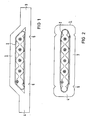
- a four- or five-wire ribbon cable 1 shown in FIGS. 1 and 2 is shielded all around by a copper grid 2 and protected from the risk of conductor damage by a strong plastic jacket as an insulating jacket 3.
- a ribbon cable can alternatively be used which, for example, alternately offers conductors twisted in pairs over approx. 1000 mm and routed in parallel over 50 mm.
- the parallel sections that can be contacted would have to be identified on the outside of the plastic jacket 3.
- the embodiments of the ribbon cable 1 according to FIG. 1 and FIG. 2 differ only in the shape of the plastic sheath 3. They have the same configuration rich of lateral webs 4 approaches 5 for guiding a cutting tool, not shown, which allows a partial separation of the plastic jacket 3 and the copper grid 2 as a screen.
- a contacting point 6 shown in FIGS. 3 and 4 can be prepared in a simple manner with standard tools (front cutters and scissors).
- the laterally separated shield 2 remains on the underside 2b; on the upper side 2a it can be contacted, for example, by a spring plate shown in FIG. 5.
- the ribbon cables exposed in this way enable contacting with a plug connector 7 (eg subminiature D plug) via the insulation displacement contacts shown in FIGS. 5 and 6.
- the plug connector 7 is attached to the contact point 6 in the known insulation displacement technique, the upper part 7a being provided with the connections which are led out and with the insulation displacement contacts.
- the lower part 7b is inserted laterally between the shield part 2b and the insulated conductors of the ribbon cable 1.
- the two parts of the connector 7 are pressed together using a suitable tool.
- a connection of the shield part 2a on the top can be made by a spring plate as an elastic connector 8 on the connector 7.
- the contact point together with plug connector 7 can furthermore be protected mechanically and in a dustproof and splashproof manner by a housing with sealing elements.
Landscapes
- Details Of Connecting Devices For Male And Female Coupling (AREA)
- Coupling Device And Connection With Printed Circuit (AREA)
- Multi-Conductor Connections (AREA)
Applications Claiming Priority (2)
| Application Number | Priority Date | Filing Date | Title |
|---|---|---|---|
| DE3619370 | 1986-06-09 | ||
| DE19863619370 DE3619370A1 (de) | 1986-06-09 | 1986-06-09 | Verfahren und anordnung zur kontaktierung von geschirmten flachbandkabeln |
Publications (1)
| Publication Number | Publication Date |
|---|---|
| EP0249155A1 true EP0249155A1 (fr) | 1987-12-16 |
Family
ID=6302617
Family Applications (1)
| Application Number | Title | Priority Date | Filing Date |
|---|---|---|---|
| EP87108123A Withdrawn EP0249155A1 (fr) | 1986-06-09 | 1987-06-04 | Procédé et dispositif d'établissement de contact avec des câbles rubans plats |
Country Status (3)
| Country | Link |
|---|---|
| US (1) | US4768287A (fr) |
| EP (1) | EP0249155A1 (fr) |
| DE (1) | DE3619370A1 (fr) |
Cited By (2)
| Publication number | Priority date | Publication date | Assignee | Title |
|---|---|---|---|---|
| EP0550855A3 (fr) * | 1992-01-06 | 1994-01-12 | Molex Inc | |
| EP0726623A3 (fr) * | 1995-02-07 | 1997-09-10 | Lumberg Karl Gmbh & Co | Dispositif de connexion pour le libre rétablissement d'une connexion électrique réutilisable, par exemple pour le branchement sur des lignes électriques à soins multiples |
Families Citing this family (5)
| Publication number | Priority date | Publication date | Assignee | Title |
|---|---|---|---|---|
| DE3840014C2 (de) * | 1988-11-26 | 1997-02-06 | Kabelmetal Electro Gmbh | Verfahren zur Herstellung einer elektrisch leitenden Verbindung mit einem Flachleiter |
| US5669775A (en) * | 1995-09-05 | 1997-09-23 | International Business Machines Corporation | Assembly for mounting components to flexible cables |
| EP3264426B1 (fr) * | 2016-06-30 | 2019-01-09 | MD Elektronik GmbH | Cable electrique blinde et sa methode de fabrication |
| JP7042404B2 (ja) * | 2019-03-05 | 2022-03-28 | 株式会社オートネットワーク技術研究所 | ワイヤハーネスモジュールおよびワイヤハーネス配索装置 |
| JP7042405B2 (ja) * | 2019-03-05 | 2022-03-28 | 株式会社オートネットワーク技術研究所 | ワイヤハーネスユニットおよびワイヤハーネスの取付構造 |
Citations (4)
| Publication number | Priority date | Publication date | Assignee | Title |
|---|---|---|---|---|
| FR2208213A1 (fr) * | 1972-11-25 | 1974-06-21 | Bbc Brown Boveri & Cie | |
| US4319075A (en) * | 1981-01-26 | 1982-03-09 | Amp Inc. | Sealed routing of undercarpet cable |
| EP0090494A1 (fr) * | 1982-03-04 | 1983-10-05 | AMP INCORPORATED (a New Jersey corporation) | Assemblage de connecteur pour câble sous tapis |
| US4488125A (en) * | 1982-07-06 | 1984-12-11 | Brand-Rex Company | Coaxial cable structures and methods for manufacturing the same |
Family Cites Families (8)
| Publication number | Priority date | Publication date | Assignee | Title |
|---|---|---|---|---|
| US3757029A (en) * | 1972-08-14 | 1973-09-04 | Thomas & Betts Corp | Shielded flat cable |
| GB1452058A (en) * | 1973-02-13 | 1976-10-06 | Henkel & Cie Gmbh | Cyclic amino phosphonic acids |
| US4287385A (en) * | 1979-09-12 | 1981-09-01 | Carlisle Corporation | Shielded flat cable |
| US4367585A (en) * | 1979-12-26 | 1983-01-11 | Western Electric Company, Inc. | Methods for the termination and connectorization of multi-conductor flat cable |
| US4345811A (en) * | 1980-03-27 | 1982-08-24 | Burroughs Corporation | Flat ribbon cable shield |
| JPS5957866U (ja) * | 1982-10-08 | 1984-04-16 | 松下電工株式会社 | フラツトケ−ブルの接続部の構造 |
| US4487995A (en) * | 1983-01-19 | 1984-12-11 | Magnum Shielding Corp. | Anchoring braided metal sheath on ignition wire |
| US4615114A (en) * | 1984-03-12 | 1986-10-07 | Asea Electric, Incorporated | Method of manufacturing molded buswork for power distribution systems |
-
1986
- 1986-06-09 DE DE19863619370 patent/DE3619370A1/de not_active Withdrawn
-
1987
- 1987-06-04 EP EP87108123A patent/EP0249155A1/fr not_active Withdrawn
- 1987-06-09 US US07/059,795 patent/US4768287A/en not_active Expired - Fee Related
Patent Citations (4)
| Publication number | Priority date | Publication date | Assignee | Title |
|---|---|---|---|---|
| FR2208213A1 (fr) * | 1972-11-25 | 1974-06-21 | Bbc Brown Boveri & Cie | |
| US4319075A (en) * | 1981-01-26 | 1982-03-09 | Amp Inc. | Sealed routing of undercarpet cable |
| EP0090494A1 (fr) * | 1982-03-04 | 1983-10-05 | AMP INCORPORATED (a New Jersey corporation) | Assemblage de connecteur pour câble sous tapis |
| US4488125A (en) * | 1982-07-06 | 1984-12-11 | Brand-Rex Company | Coaxial cable structures and methods for manufacturing the same |
Cited By (2)
| Publication number | Priority date | Publication date | Assignee | Title |
|---|---|---|---|---|
| EP0550855A3 (fr) * | 1992-01-06 | 1994-01-12 | Molex Inc | |
| EP0726623A3 (fr) * | 1995-02-07 | 1997-09-10 | Lumberg Karl Gmbh & Co | Dispositif de connexion pour le libre rétablissement d'une connexion électrique réutilisable, par exemple pour le branchement sur des lignes électriques à soins multiples |
Also Published As
| Publication number | Publication date |
|---|---|
| DE3619370A1 (de) | 1987-12-10 |
| US4768287A (en) | 1988-09-06 |
Similar Documents
| Publication | Publication Date | Title |
|---|---|---|
| DE4015238C2 (fr) | ||
| DE3883643T2 (de) | Flachkabelverbinder. | |
| DE4217205C2 (de) | Steckverbinder | |
| DE10328598A1 (de) | Kabelverbinder | |
| DE19906725C1 (de) | Leiteranschlußelement | |
| DE69014083T2 (de) | Elektrischer Verbinder. | |
| DE102007026094A1 (de) | Kontaktelement für einen Steckverbinder für Leiterplatten | |
| EP0643454A1 (fr) | Module de connexion | |
| DE102007026097A1 (de) | Steckverbinder für Leiterplatten | |
| EP0249155A1 (fr) | Procédé et dispositif d'établissement de contact avec des câbles rubans plats | |
| DE3203651A1 (de) | Steckverbinder und verbinder leiterplatte-kabel mit schneid-klemmkontaktanschluessen zum anschliessen von kabeln mit mehreren, mechanisch voneinander unabhaenigen, einzelleitern | |
| DE102010034790B4 (de) | Kontaktträger für wenigstens eine Vorrichtung zur Kontaktierung eines elektrischen Leiters mit einer Leiterbahn | |
| DE19618998C1 (de) | Kontaktierungsvorrichtung | |
| DE2620267C3 (de) | Dreireihiger Leitungsstecker zum Anschließen von Flachbandkabeln an Schaltungsplatten | |
| DE1465659B1 (de) | Leitungsverbinder zum Anschluss an Vielfachader-Bandkabel | |
| DE202010011546U1 (de) | Vorrichtung zur Kontaktierung eines elektrischen Leiters mit einer Leiterbahn und Kontaktträger für eine solche Vorrichtung | |
| DE4412783A1 (de) | Verteiler für Busleitungen | |
| EP0918369A2 (fr) | Dispositif de raccordement de conducteurs électriques | |
| DE3543200A1 (de) | Flachkabelverbinder | |
| EP0667650A2 (fr) | Système de connexion modulaire | |
| DE3743841A1 (de) | Elektrooptische anzeigevorrichtung | |
| DE19506713C2 (de) | Mehrpoliger Steckverbinder | |
| DE102022119534A1 (de) | Verteiler eines insbesondere 4-poligen Stecksystemes | |
| EP1187256B1 (fr) | Elément de connexion électrique | |
| DE10055148A1 (de) | Kabelanschluß- oder -verbindungseinrichtung |
Legal Events
| Date | Code | Title | Description |
|---|---|---|---|
| PUAI | Public reference made under article 153(3) epc to a published international application that has entered the european phase |
Free format text: ORIGINAL CODE: 0009012 |
|
| AK | Designated contracting states |
Kind code of ref document: A1 Designated state(s): AT CH DE FR GB IT LI |
|
| 17P | Request for examination filed |
Effective date: 19880608 |
|
| 17Q | First examination report despatched |
Effective date: 19910304 |
|
| STAA | Information on the status of an ep patent application or granted ep patent |
Free format text: STATUS: THE APPLICATION IS DEEMED TO BE WITHDRAWN |
|
| 18D | Application deemed to be withdrawn |
Effective date: 19910716 |
|
| RIN1 | Information on inventor provided before grant (corrected) |
Inventor name: THIES, WERNER, DIPL.-ING. |