EP0249175A2 - Pompe - Google Patents
Pompe Download PDFInfo
- Publication number
- EP0249175A2 EP0249175A2 EP87108222A EP87108222A EP0249175A2 EP 0249175 A2 EP0249175 A2 EP 0249175A2 EP 87108222 A EP87108222 A EP 87108222A EP 87108222 A EP87108222 A EP 87108222A EP 0249175 A2 EP0249175 A2 EP 0249175A2
- Authority
- EP
- European Patent Office
- Prior art keywords
- pump
- piston
- drum
- fluid
- pump means
- Prior art date
- Legal status (The legal status is an assumption and is not a legal conclusion. Google has not performed a legal analysis and makes no representation as to the accuracy of the status listed.)
- Withdrawn
Links
Images

Classifications
-
- F—MECHANICAL ENGINEERING; LIGHTING; HEATING; WEAPONS; BLASTING
- F04—POSITIVE - DISPLACEMENT MACHINES FOR LIQUIDS; PUMPS FOR LIQUIDS OR ELASTIC FLUIDS
- F04B—POSITIVE-DISPLACEMENT MACHINES FOR LIQUIDS; PUMPS
- F04B9/00—Piston machines or pumps characterised by the driving or driven means to or from their working members
- F04B9/08—Piston machines or pumps characterised by the driving or driven means to or from their working members the means being fluid
- F04B9/10—Piston machines or pumps characterised by the driving or driven means to or from their working members the means being fluid the fluid being liquid
- F04B9/109—Piston machines or pumps characterised by the driving or driven means to or from their working members the means being fluid the fluid being liquid having plural pumping chambers
- F04B9/117—Piston machines or pumps characterised by the driving or driven means to or from their working members the means being fluid the fluid being liquid having plural pumping chambers the pumping members not being mechanically connected to each other
- F04B9/1176—Piston machines or pumps characterised by the driving or driven means to or from their working members the means being fluid the fluid being liquid having plural pumping chambers the pumping members not being mechanically connected to each other the movement of each piston in one direction being obtained by a single-acting piston liquid motor
- F04B9/1178—Piston machines or pumps characterised by the driving or driven means to or from their working members the means being fluid the fluid being liquid having plural pumping chambers the pumping members not being mechanically connected to each other the movement of each piston in one direction being obtained by a single-acting piston liquid motor the movement in the other direction being obtained by a hydraulic connection between the liquid motor cylinders
-
- F—MECHANICAL ENGINEERING; LIGHTING; HEATING; WEAPONS; BLASTING
- F04—POSITIVE - DISPLACEMENT MACHINES FOR LIQUIDS; PUMPS FOR LIQUIDS OR ELASTIC FLUIDS
- F04B—POSITIVE-DISPLACEMENT MACHINES FOR LIQUIDS; PUMPS
- F04B1/00—Multi-cylinder machines or pumps characterised by number or arrangement of cylinders
- F04B1/12—Multi-cylinder machines or pumps characterised by number or arrangement of cylinders having cylinder axes coaxial with, or parallel or inclined to, main shaft axis
- F04B1/20—Multi-cylinder machines or pumps characterised by number or arrangement of cylinders having cylinder axes coaxial with, or parallel or inclined to, main shaft axis having rotary cylinder block
Definitions
- the invention relates to a pump means according to the precharacterising part of Claim 1.
- the pump means is fluid-driven with a pressurized driving fluid which exerts pressure on drive pistons connected to pump pistons in cylinder spaces in a rotating drum.
- a hydraulically driven pump means in which several axial cylinder spaces in a rotor are arranged concentrically to each other and comprise drive pistons which are each connected to a pump piston. At one end of the pump means, a driving fluid is supplied and discharged, and at the other end of the pump means a pump flow is supplied and discharged.
- Other technical solutions involving several conically arranged cylinder spaces in a rotor in which, in each cylinder space, a drive piston is connected to a pump piston are known from US-A-4 500 261. When the motor is driven, the hydraulic pressure acts on the drive piston, connected to the pump piston, for pumping the flow medium.
- the invention suggests a pump means according to the introductory part of Claim 1, which is characterized by the features of the characterizing part of Claim 1.
- the pump means mainly consists of a closed rotating drum, which is journalled in and surrounded in a sealed manner by a pump housing.
- the end walls of the housing are provided with gate openings for the supply and discharge of a driving fluid and a medium to be pumped.
- the drum accommodates a number of cylinders with drive pistons which are each connected to a corresponding pump piston.
- the pump means may, for example, be conceived to be used as an underwater pump for pumping a well flow from a drill hole on the bottom of the sea.
- the underwater pump is then placed on the sea bottom in immediate proximity to the drill hole, and the well flow can be pumped directly to shore for further treatment.
- the pump With the sealed surrounding pump housing, the pump will be relatively insensitive to an external corrosive environment.
- the enclosed movable parts are few in number and move at a relatively low speed and are surrounded by a liquid. All this contributes to ensure a minimum internal wear.
- the design and function of the pump means deviate to a considerable extent from prior art pump designs. It is robust, insensitive and flexible, which allows for a wide range of applications.
- the pump means is relatively insensitive to uncertainties or changes in well data, for example, pressure, flow, free gas volume (gas/oil ratio), the presence of sand (abrasion), that is to say, the pump can be utilized during the entire lifetime of an oil reservoir without the efficiency and function being deteriorated. Furthermore, the pump is insensitive to a multi-phase flow and different flow states because of a robust design and the low velocities of movable parts. This eliminates the need of separators and/or mixers on the suction side of the pump.
- a great flexibility may also prevail regarding the choice of the driving flow to the pistons.
- water from, for example, a pressurized aqueous sphere or an untreated well stream with sufficient driving pressure may be used.
- slugs since the structural parts included are robust and work at a low speed, resulting in low dynamic strain.
- the pump may have a very large working range both with regard to pressure and to flow.
- a centrifugal pump on the other hand, is very sensitive when deviating from its most favourable operating point.
- the flow can be regulated in a simple manner by varying the speed and the length of the stroke, which is made by varying the pressure of the driving flow.
- the efficiency lies at about 90%, which is considerably higher than with a hydraulically turbine driven centrifugal pump.
- the pump means may be completely hydraulically driven, eliminating the need of electric power supply. All potential error sources from an electric power supply items, such as cables, electric underwater couplings, transformers, electric motors, instrumentation and monitoring devices, are eliminated. The need of instrumentation for measuring, monitoring and controlling is reduced in comparison with centrifuge pumps.
- the pump means according to the invention is a type of displacement pump, whereby, in principle, the flow is known when the speed and stroke of the pump are known.
- a slow rotation and low relative speeds between the structural parts included reduce the risk of wear. Revolution rates lower than 100 r.p.m. are here to be compared with centrifugal pumps with speeds amounting to 3,000-8,000 r.p.m..
- the rotary motion can be brought about by a slowly rotating hydraulic motor with direct drive.
- the design principle of a hydraulic motor makes it suited for operation in water at large ocean depths.
- the pump means may be provided with piston rings and wear rings, which may be replaced in pre-determined intervals and which are prepared for a simple replacement.
- Great freedom is provided as regards the choice of materials, which is not dependent on the constructive aspects of pump technique.
- "exotic” materials for example ceramic materials, are therefore a fully feasible alternative.
- the movements of the pump pistons contribute to "self-cleansing" of the pump cylinders in view of, for example, wax deposits.
- the design allows "pigs” of a simple design to be transported through the pump.
- the pump is housed within a totally enclosed cylindrical pump housing, which is capable of withstanding the external overpressure prevailing at great ocean depths and which may have a small number of couplings for the hydraulic connections.
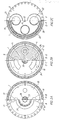
- the pump means illustrated in the Figures consists of a closed and sealed pump housing 1 with end walls 2,3.
- the end walls 2,3 ar provided with connection openings for a driving fluid and a pump flow.
- a drive motor is connected to one end wall 2.
- the pump housing 1 encloses a rotatable drum 4.
- the drum 4 contains several axial cylinder spaces 5,6, which are arranged axially in pairs with a common centre line for each pair and parallel to the periphery of the drum 4.
- the centre lines of all pairs of cylinder spaces are arranged concentrically to the axis of the drum.
- the drum 4 exhibits one driving side and one pump side.
- a drive piston 7 In each cylinder space 5 on the driving side there is arranged a drive piston 7.
- a pump piston 8 In each cylinder space 6 on the pump side there is arranged a pump piston 8.
- the cylinder spaces 5 on the driving side are separated from the cylinder spaces 6 on the pump side by a partition wall 12.
- each drive piston 7 on the driving side is connected to a pump piston 8 on the pump side by means of a piston rod 9 which passes in a sealed manner through the partition wall 12.
- a space 10 behind each drive piston 7 is connected to a first connecting channel 11 through the partition wall 12.
- a space 13 behind each pump piston 8 is connected to a second connecting channel 14 through the partition wall 12. In this way all the spaces 13 behind the pump pistons 8 are connected to each other.
- the first end wall 2 there are a connection opening 15 for the supplied driving fluid and a connection opening 16 for the spent/discharged driving fluid.
- an upper opening 17 is arranged in communication with the connection opening 15 for conveying driving fluid to a corresponding opening in the rotatable drum 4.
- a lower opening 18 is arranged in communication with the connection opening 16 for conveying driving fluid from a corresponding opening in the rotatable drum 4.
- an upper opening 19 is arranged for conveying discharged pump flow from a corresponding opening in the rotatable drum 4 to an outer connection opening 21 in the end wall 3.
- a lower opening 20 is arranged for conveying supplied pump flow to a corresponding opening in the rotatable drum 4 from an external connection opening 22 in the end wall 3.
- the rotatable drum 4 is journalled at its ends by means of hydrostatic sliding bearings 23 and is otherwise surrounded by a cavity 24, for example filled with a fluid.
- the pump housing 1 supports the sliding bearings 23 and is separated from the rotatable drum 4 by means of the cavity 24.
- a driving fluid/lubricant is supplied to the upper part of the first end wall 2 through a connection opening 25 to the hydrostatic sliding bearings 23 on the driving side and via a connecting pipe 26 to the sliding bearings 23 on the pump side.
- a fluid-driven torque motor 27 is connected to the input shaft 28 of the rotating drum 4, said input shaft 28 being journalled by a thrust bearing 29 in the first end wall 2.
- pressurized driving fluid is sup- plied through the connection opening 30 to a first inner connecting channel 31 connected to the first connecting channels 11.
- a second inner connecting channel 33 transmits the supply of fluid from a connection opening 32 to the second connecting channels 14.
- Wear surfaces 34 are provided in the end walls 2,3, acting against wear surfaces 35 in the end surfaces of the rotating drum.
- the wear surfaces 34,35 are formed with the openings 17,18,19,20 necessary for the passage of driving fluid and pump flow.
- An external sealed space 36,37 is arranged around the drive and pump cylinders 5,6 and inside the envelope surface of the drum 4.
- An internal sealed space 38,39 is arranged inside the drive and pump cylinders 5,6.
- the cavity 24 between the pump housing 1 and the drum -4 may be filled with a pressurized fluid to counteract the effect of an external aggressive environment under overpressure.
- pressurized driving fluid is supplied to the fluid-operated motor 27 for rotation of the drum 4 and to the connection openings 15 in the first end wall 2, and further to the upper opening 17.
- the drum 4 rotates, the cylinder spaces 5,6 pass the openings in sequence.
- the driving fluid is supplied to the cylinder space 5 and presses the drive piston 7 inwards, whereby at the same time the assembled pump piston 8 is moved outwards thereby pressing the received pump flow out through the opening 19 to the connection opening 21.
- the driving fluid behind the piston which is supplied through the connection opening 30,31, will be transmitted via the first connecting channel 11 under pressure to the space 10 behind the drive piston 7 on the opposite side of the drum 4, which is thereby moved back while at the same time the assembled pump piston 8 is moved inwards. From the connec- tion opening 22 and the opening 20, the pump flow can then be received by the cylinder space 6 on the pump side. Also in this case the spaces 13 behind the pump pistons 8 are interconnected. Through the connection 32,33, fluid is supplied to the second connecting channel 14. During the return movement of the drive piston 7, the spent driving fluid will be restored through the opening 18 to the connection opening 16 in the end wall 2. Then, during the rotation of the drum 4, pump flow supplied in the lower position will be discharged in the upper position whereas driving fluid is supplied in the upper position and is discharged in the lower position.
Landscapes
- Engineering & Computer Science (AREA)
- Mechanical Engineering (AREA)
- General Engineering & Computer Science (AREA)
- Reciprocating Pumps (AREA)
- Electromagnetic Pumps, Or The Like (AREA)
- Eye Examination Apparatus (AREA)
- Details Of Reciprocating Pumps (AREA)
Applications Claiming Priority (2)
| Application Number | Priority Date | Filing Date | Title |
|---|---|---|---|
| SE8602651A SE8602651L (sv) | 1986-06-13 | 1986-06-13 | Pumpanordning |
| SE8602651 | 1986-06-13 |
Publications (2)
| Publication Number | Publication Date |
|---|---|
| EP0249175A2 true EP0249175A2 (fr) | 1987-12-16 |
| EP0249175A3 EP0249175A3 (fr) | 1989-07-19 |
Family
ID=20364811
Family Applications (1)
| Application Number | Title | Priority Date | Filing Date |
|---|---|---|---|
| EP87108222A Withdrawn EP0249175A3 (fr) | 1986-06-13 | 1987-06-06 | Pompe |
Country Status (7)
| Country | Link |
|---|---|
| US (1) | US4752192A (fr) |
| EP (1) | EP0249175A3 (fr) |
| JP (1) | JPS62298669A (fr) |
| BR (1) | BR8703001A (fr) |
| NL (1) | NL8702528A (fr) |
| NO (1) | NO872460L (fr) |
| SE (1) | SE8602651L (fr) |
Cited By (4)
| Publication number | Priority date | Publication date | Assignee | Title |
|---|---|---|---|---|
| EP0422745A1 (fr) * | 1989-10-13 | 1991-04-17 | Pieter Faber | Dispositif de pompage de béton |
| WO1991019094A1 (fr) * | 1990-06-05 | 1991-12-12 | Abb Mineral Slurry Transportation Pty. Ltd. | Ensemble d'orifices de soupape pour une pompe hydraulique refoulante a corps rotatif |
| AU646051B2 (en) * | 1990-06-05 | 1994-02-03 | Abb Mineral Slurry Transportation Pty Ltd | Valve porting for rotating barrel ram pump |
| CN101922428A (zh) * | 2009-06-15 | 2010-12-22 | 刘延兵 | 一种沼气池手动双缸出渣泵 |
Families Citing this family (4)
| Publication number | Priority date | Publication date | Assignee | Title |
|---|---|---|---|---|
| DE19983502T1 (de) | 1998-09-02 | 2001-06-28 | Caterpillar Inc | Pumpenvorrichtung für hydraulisch angetriebene Brennstoffeinspritzsysteme |
| US20030085036A1 (en) * | 2001-10-11 | 2003-05-08 | Curtis Glen A | Combination well kick off and gas lift booster unit |
| US6672263B2 (en) * | 2002-03-06 | 2004-01-06 | Tony Vallejos | Reciprocating and rotary internal combustion engine, compressor and pump |
| US6821096B2 (en) * | 2002-08-30 | 2004-11-23 | Illinois Tool Works Inc. | Multiple component metering and dispensing system |
Family Cites Families (11)
| Publication number | Priority date | Publication date | Assignee | Title |
|---|---|---|---|---|
| FR910526A (fr) * | 1945-04-27 | 1946-06-11 | Pompe à béton | |
| BE464613A (fr) * | 1946-04-16 | |||
| BE488198A (fr) * | 1948-04-02 | |||
| DE903900C (de) * | 1951-10-02 | 1954-02-11 | Kurt Bernard Schoenenberger | Hydraulischer Druckwandler |
| FR1129043A (fr) * | 1955-05-27 | 1957-01-15 | Transformateur hydraulique | |
| US2847984A (en) * | 1955-11-07 | 1958-08-19 | Gen Motors Corp | Hydraulic engine-starting device |
| US3405641A (en) * | 1967-05-25 | 1968-10-15 | Kobe Inc | Rotary, fluid operated, axial plunger pump |
| US3516761A (en) * | 1968-10-10 | 1970-06-23 | Drilling Well Control Inc | Fluid actuated hydraulic pump |
| DE2147984C3 (de) * | 1971-09-25 | 1975-05-07 | Hellmuth Walter Gmbh, 2300 Kiel | Steuervorrichtung für einen Druckflüssigkeits-Schubkolbenmotor |
| GB1414997A (en) * | 1971-11-29 | 1975-11-26 | Boyle B A | Rotating cylinder block pump |
| SE449391B (sv) * | 1982-04-07 | 1987-04-27 | Asea Atom Ab | Kolvpumpanordning for pumpning av en blandning av grovkornigt material och vetska |
-
1986
- 1986-06-13 SE SE8602651A patent/SE8602651L/ not_active Application Discontinuation
-
1987
- 1987-06-06 EP EP87108222A patent/EP0249175A3/fr not_active Withdrawn
- 1987-06-11 JP JP62144226A patent/JPS62298669A/ja active Pending
- 1987-06-12 NO NO872460A patent/NO872460L/no unknown
- 1987-06-12 US US07/060,819 patent/US4752192A/en not_active Expired - Fee Related
- 1987-06-12 BR BR8703001A patent/BR8703001A/pt unknown
- 1987-10-22 NL NL8702528A patent/NL8702528A/nl not_active Application Discontinuation
Cited By (6)
| Publication number | Priority date | Publication date | Assignee | Title |
|---|---|---|---|---|
| EP0422745A1 (fr) * | 1989-10-13 | 1991-04-17 | Pieter Faber | Dispositif de pompage de béton |
| US5114319A (en) * | 1989-10-13 | 1992-05-19 | Pieter Faber | Concrete-pumping device |
| WO1991019094A1 (fr) * | 1990-06-05 | 1991-12-12 | Abb Mineral Slurry Transportation Pty. Ltd. | Ensemble d'orifices de soupape pour une pompe hydraulique refoulante a corps rotatif |
| AU646051B2 (en) * | 1990-06-05 | 1994-02-03 | Abb Mineral Slurry Transportation Pty Ltd | Valve porting for rotating barrel ram pump |
| US5316451A (en) * | 1990-06-05 | 1994-05-31 | Abb Mineral Slurry Transportation Pty. Ltd. | Valve porting for rotating barrel ram pump |
| CN101922428A (zh) * | 2009-06-15 | 2010-12-22 | 刘延兵 | 一种沼气池手动双缸出渣泵 |
Also Published As
| Publication number | Publication date |
|---|---|
| NO872460D0 (no) | 1987-06-12 |
| SE8602651D0 (sv) | 1986-06-13 |
| EP0249175A3 (fr) | 1989-07-19 |
| BR8703001A (pt) | 1988-03-08 |
| NO872460L (no) | 1987-12-14 |
| NL8702528A (nl) | 1989-05-16 |
| US4752192A (en) | 1988-06-21 |
| JPS62298669A (ja) | 1987-12-25 |
| SE8602651L (sv) | 1987-12-14 |
Similar Documents
| Publication | Publication Date | Title |
|---|---|---|
| US8388327B2 (en) | Progressing cavity pump with several pump sections | |
| EP1007853A1 (fr) | Appareil a rotor en forme de vis, fonctionnant sans huile | |
| EP0249175A2 (fr) | Pompe | |
| EP0627557A1 (fr) | Machine fluidique à vis | |
| US4520712A (en) | Axial piston machine having a sealed bearing box | |
| EP1007796B1 (fr) | Ameliorations concernant un appareil d'excavation sous-marine | |
| US3999895A (en) | Rotating barrel pump | |
| US4433947A (en) | Slurry feed pump for coal liquefaction reactors | |
| RU2012823C1 (ru) | Объемная роторная гидромашина | |
| EP0120058A1 (fr) | Pompe a ailettes doubles | |
| SE437067B (sv) | Kompressoraggregat | |
| US4876946A (en) | Flexible hose pump | |
| CN2353937Y (zh) | 柱塞式滚柱泵 | |
| WO1995012758A1 (fr) | Pompe ou moteur volumetrique | |
| EP0223335A2 (fr) | Machines rotatives fluidiques à déplacement positif | |
| EP3737836B1 (fr) | Machine rotative à palettes coulissantes dotée de paliers coulissants hydrostatiques pour les palettes | |
| WO1992008871A1 (fr) | Convertisseur de pression | |
| US4772184A (en) | Piston pump for abrasive conveyances | |
| EP1053400B1 (fr) | Moteur hydraulique avec conduite de lubrification | |
| RU2756825C1 (ru) | Роторно-пластинчатое устройство для преобразования возвратно-поступательного движения во вращательное, без кривошипно-шатунного механизма | |
| RU2118711C1 (ru) | Коловратный гидронасос переменной производительности | |
| WO1997020145A1 (fr) | Dispositif d'etancheite axial | |
| AU737332B2 (en) | Improvements in or relating to underwater excavation apparatus | |
| CN121866401A (zh) | 具有集成轴向活塞能量回收设备的轴向柱塞泵 | |
| US4134426A (en) | Seawater hydraulic motor distributing valve based on a hydrosphere bearing |
Legal Events
| Date | Code | Title | Description |
|---|---|---|---|
| PUAI | Public reference made under article 153(3) epc to a published international application that has entered the european phase |
Free format text: ORIGINAL CODE: 0009012 |
|
| AK | Designated contracting states |
Kind code of ref document: A2 Designated state(s): DE FR GB |
|
| PUAL | Search report despatched |
Free format text: ORIGINAL CODE: 0009013 |
|
| AK | Designated contracting states |
Kind code of ref document: A3 Designated state(s): DE FR GB |
|
| 17P | Request for examination filed |
Effective date: 19891127 |
|
| 17Q | First examination report despatched |
Effective date: 19910708 |
|
| STAA | Information on the status of an ep patent application or granted ep patent |
Free format text: STATUS: THE APPLICATION HAS BEEN WITHDRAWN |
|
| 18W | Application withdrawn |
Withdrawal date: 19900901 |
|
| RIN1 | Information on inventor provided before grant (corrected) |
Inventor name: BENGT, ODE |