EP0249181A2 - Connecteur pour la connexion électrique de remorques - Google Patents
Connecteur pour la connexion électrique de remorques Download PDFInfo
- Publication number
- EP0249181A2 EP0249181A2 EP87108259A EP87108259A EP0249181A2 EP 0249181 A2 EP0249181 A2 EP 0249181A2 EP 87108259 A EP87108259 A EP 87108259A EP 87108259 A EP87108259 A EP 87108259A EP 0249181 A2 EP0249181 A2 EP 0249181A2
- Authority
- EP
- European Patent Office
- Prior art keywords
- bayonet
- bayonet ring
- inner sleeve
- locking
- plug
- Prior art date
- Legal status (The legal status is an assumption and is not a legal conclusion. Google has not performed a legal analysis and makes no representation as to the accuracy of the status listed.)
- Granted
Links
Images


Classifications
-
- H—ELECTRICITY
- H01—ELECTRIC ELEMENTS
- H01R—ELECTRICALLY-CONDUCTIVE CONNECTIONS; STRUCTURAL ASSOCIATIONS OF A PLURALITY OF MUTUALLY-INSULATED ELECTRICAL CONNECTING ELEMENTS; COUPLING DEVICES; CURRENT COLLECTORS
- H01R13/00—Details of coupling devices of the kinds covered by groups H01R12/70 or H01R24/00 - H01R33/00
- H01R13/62—Means for facilitating engagement or disengagement of coupling parts or for holding them in engagement
- H01R13/625—Casing or ring with bayonet engagement
-
- H—ELECTRICITY
- H01—ELECTRIC ELEMENTS
- H01R—ELECTRICALLY-CONDUCTIVE CONNECTIONS; STRUCTURAL ASSOCIATIONS OF A PLURALITY OF MUTUALLY-INSULATED ELECTRICAL CONNECTING ELEMENTS; COUPLING DEVICES; CURRENT COLLECTORS
- H01R13/00—Details of coupling devices of the kinds covered by groups H01R12/70 or H01R24/00 - H01R33/00
- H01R13/44—Means for preventing access to live contacts
- H01R13/447—Shutter or cover plate
Definitions
- the invention relates to a plug for a plug connection for the electrical connection of motor vehicle trailers, with a housing inserting a contact insert with contact pins, consisting at least of a cap and a bayonet connection part for connection to a socket, and with a cover support platform for supporting the socket cover in the open position.
- the object of the present invention is to improve a plug of this type in such a way that it is easy to handle, easy to manufacture, safe to use and durable in function.
- the bayonet connection part consists of an inner sleeve on which a bayonet ring is rotatably mounted and with which the cap can be screwed while axially fixing the contact insert.
- the lid support platform is preferably attached to the bayonet ring and rotatable with it, namely that the lid support platform is attached to the bayonet ring in such an angular position that in the locking position of the bayonet ring in the socket it has the correct position relative to the socket and its cover, so that the opened one can Cover the socket with the plug inserted on the lid support platform, so that its inner seal is protected.
- the stability is the lid support platform is particularly good.
- the division level can, in particular, essentially coincide with the level of the end of the bayonet ring on the cable connection side, which, in addition to simplifying production, also improves the manageability when assembling and using the plug.
- the plate section can also serve as an interchangeable emblem carrier, it preferably carries elevations and / or depressions in the form of letters, numbers, marks or the like on its upper side. These can also be provided in a special interchangeable insert of the plate section.
- a particularly advantageous embodiment of the invention consists in that the inner sleeve projects beyond the bayonet ring on the socket end with an annular bead attachment, the outer diameter of which is larger than the inner diameter of the bayonet ring, and in that the inner sleeve with an outer shoulder facing the socket end rests on an inner shoulder of the bayonet ring in the axial direction. This ensures that the bayonet ring can be easily rotated on the inner sleeve with axial immovability between the annular bead attachment and the outer shoulder of the inner sleeve.
- the assembly of the inner sleeve and the bayonet ring can be done by fitting one into the other, so that the bayonet ring is axially fixed relative to the inner sleeve between the annular bead attachment and the outer shoulder of the inner sleeve, but the rotatability of the two parts relative to one another is ensured.
- the bayonet ring with the inner sleeve is in the bayonet unlocked rotational position, i.e. releasably locked in the position in which the bayonet ring is rotated out of engagement with the socket in its initial rotational position.
- the plug is overall easy to insert and, combined with the correct rotational arrangement of the contact insert in the inner sleeve, is also easy to find.
- the initial insertion of the plug into the socket thus takes place in the releasably fixed starting rotational position of the bayonet ring, so that the plug connection can always be made easily and quickly.
- the bayonet ring returns by rotating it from the locked rotational position with the socket into this releasably fixed starting rotational position, so that it is always in the correct rotational orientation for a new insertion process.
- the bayonet ring preferably has a partially annular groove on its inside, in which a radial projection of the inner sleeve is guided; In one end region of the groove, a locking projection is provided, which can be run over by the projection of the inner sleeve during rotation into the locking position.
- the latching projection preferably has a run-up slope for the projection of the inner sleeve which is effective when the bayonet ring is rotated in the bayonet unlocking position and a relatively steep latching edge on the side opposite in the direction of rotation. This ensures that the bayonet ring can be easily brought into the releasably fixed starting rotational position, but can only be released from it again with greater effort, so that an unwanted accidental release from the latching position is largely avoided.
- a special feature of the invention can also be seen in the fact that, in the case of a plug with a form-fitting, preferably inevitably unlockable when the bayonet connector part is inserted into the associated socket, the bayonet ring with the inner sleeve in the bayonet unlocking position can be inserted into a bayonet unlocking position from an opening in the front section into the socket the bayonet ring is provided with a radially protruding unlocking pin which is supported on a locking spring which, in the bayonet unlocking position, blocks rotation of the bayonet ring relative to the inner sleeve and releases it when the unlocking pin is depressed.
- the bayonet ring When the bayonet ring is initially inserted axially into the socket, the unlocking pin is pressed down at the edge of the can opening. Due to such a forced unlocking or locking, the bayonet ring can be rotated against the inner sleeve with simple technical means if the bayonet connector is plugged into the associated socket, while it is otherwise locked against the inner sleeve. As a result, the bayonet ring and inner sleeve can be rotated as a unit and inserted into the correct insertion position before the plug is inserted into the socket. The lock is only released when the plug is inserted into the Can solved. This measure makes the handling of the plug according to the invention even easier and easier.
- the unlocking pin is inevitably and slightly depressed when the plug is plugged into the socket, it can preferably have a socket slope facing the socket.
- the unlocking pin can be supported on the locking spring via a platform.
- the unlocking pin is preferably located off-center on the platform, so that the pin is always inserted into the opening of the bayonet ring in the correct orientation with respect to the run-up slope, taking into account an inner recess of the bayonet ring provided for the platform. This always ensures correct installation.
- the platform itself is received and guided in the inner recess of the bayonet ring.
- a particularly space-saving design in the axial direction with large support of the unlocking pin and reliable function is obtained when the locking spring is designed as a leaf spring.
- a special feature of the invention is that the leaf spring is held, for example, clamped in an outer recess of the inner sleeve, and that preferably a resilient locking section protrudes from the leaf spring main body, which in the bayonet unlocking position with an inner locking edge of the bayonet ring interacts and on which the unlocking pin acts when depressed in the sense of lifting off the locking edge.
- the same spring fulfills both the reset function for the unlocking pin and the locking function, while maintaining an extremely space-saving design.
- the locking edge is formed by a side boundary of the recess of the bayonet ring receiving the platform of the unlocking pin and the platform is somewhat thinner than the depth of the recess. A special locking edge is then no longer required.
- a simple assembly and secure mounting of the leaf spring can be ensured in that the recess of the inner sleeve provided for the leaf spring has undercuts for receiving the ends of the leaf spring.
- the leaf spring preferably bears elevations or features which prevent the leaf spring from jumping out of its recess when the inner sleeve is mounted in the bayonet ring and entering the gap between the bayonet ring and the inner sleeve.
- the smoothness of the rotation of the inner sleeve relative to the bayonet ring is ensured in a development of the invention in that the inner sleeve carries guide ribs at an angular distance from one another at least on the outer surface of its front cylindrical section guided in the bayonet ring. It is only with these that the inner sleeve rests on the inner surface of the bayonet ring.
- the guide ribs can be rounded on their guide surface.
- the guide ribs can run essentially axially. However, they are preferably, for example. at an angle of 45 ° to the longitudinal axis of the connector, inclined to improve the running properties of the bayonet ring on the inner sleeve even further.
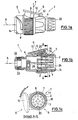
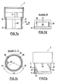
- the plug 1 for a plug connection for the electrical connection of motor vehicle trailers has a contact insert 2 with contact pins 3, which is received in a housing.
- the housing consists of a cap 4 and a bayonet connection part 5.
- a union nut 22 is screwed to fix a seal 23 against the ingress of moisture at the cable entry.
- the bayonet connection part 5 is used to connect to a socket which has corresponding projections for engaging in the bayonet grooves.
- a cover support platform 6 is also provided, on which the socket cover can lie flat in the open position so that its inner seal is protected.
- the bayonet connection part 5 consists of an inner sleeve 7 and a bayonet ring 8.
- the bayonet ring 8 is rotatably mounted on the inner sleeve 7.
- the cap 4 is screwed to the rear end of the inner sleeve 7.
- the contact insert 2 is pressed against an inner shoulder 24 of the inner sleeve 7.
- an O-ring 25 can be provided between cap 4 and inner sleeve 7, an O-ring 25. The housing is thus completely sealed when the plug is plugged into a socket.
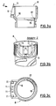
- the lid support platform 6 is attached to the bayonet ring 8 and rotatable with it.
- the lid support platform 6 is formed in two parts, namely it consists of a base section 9, which is integrally connected to the bayonet ring 8, and a plate section 10, which can be attached to the base section 9 as a separate component, e.g. can be plugged in and fastened to this, for example by means of screw 26.
- base section 9 and plate section 10 have matching guide ribs 11 and guide grooves 12, which ensure that the two sections 9, 10 are easy to assemble and hold to one another.
- the plate section 10 is arranged outside the longitudinal axis A of the socket, starting from the socket side in the direction of the cable connection side and sloping in relation to the longitudinal axis A, so that when the plug 1 is inserted into a socket, its cover is reliably level the lid support platform 6 can hang up.
- the plate section 10 is supported on the base section with a support section 13 in a division plane T, which is essentially perpendicular to the longitudinal axis A of the plug.
- the division plane T essentially coincides with the plane of the cable connection end of the bayonet ring 8 together.
- the plate section 10 preferably bears an emblem for identification.
- the inner sleeve 7 projects beyond the bayonet ring 8 on the socket side, as can be seen particularly in FIGS. 1a and 1b, with an annular bead attachment 14.
- the outer diameter of the annular bead attachment 14 is larger than the inner diameter of the bayonet ring 8 there.
- the inner sleeve 7 lies with an outer shoulder facing the socket 15 (which is formed simultaneously with the inner shoulder 24) on an inner shoulder 16 of the bayonet ring 8 axially.
- the bayonet ring 8 can be rotated slightly relative to the inner sleeve 7, but is axially immovable.
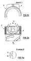
- the bayonet ring 8 is releasably locked to the inner sleeve 7 in the bayonet unlocking position.
- the bayonet ring 8 has a partially annular groove 17 (FIGS. 3a, 3c, 3d) in which a radial projection 18 of the inner sleeve 7 (FIGS. 4a, 4b and 4d) is guided.
- a latching projection 19 (FIG. 3d) is provided, which the projection 18 of the inner sleeve 7 drives over when the bayonet ring 8 is turned into the bayonet unlocking position.
- the projection 18 is then in the space between the locking projection 19 and the (in Fig.
- the locking projection 19 has an effective run-on slope for the projection 18 of the inner sleeve 7 and on the side opposite in the direction of rotation when the bayonet ring 8 is rotated into the bayonet unlocking position (in which the bayonet parts of the bayonet ring are out of engagement with the bayonet parts of the socket) relatively steep locking edge.
- the run-up slope is in Fig. 3d above, the locking edge below.
- both the contact insert 2 of the plug 1 and the contact insert of the associated socket have corresponding recesses into which the inner ribs 20, 21 fit, so that the two associated contact inserts always have the correct orientation to one another when the plug is inserted into the socket.
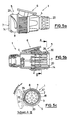
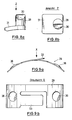
- the embodiment of the connector according to the invention according to FIGS. 5a to 9b essentially corresponds to the connector according to the invention according to FIGS. 1a to 4d, but it is equipped with a forced locking of a rotation of the inner sleeve 7 relative to the bayonet ring 8 in the bayonet unlocking position.
- the following description is therefore essentially limited to this positive locking, which prevents an unwanted rotation of the inner sleeve 7 with respect to the bayonet ring 8 before the plug 1 is inserted into a socket.
- the bayonet ring 8 and the inner sleeve 7 with the contact insert 2 always have the correct starting position.
- an unlocking pin 28 projects radially from an opening 27 in the foremost section of the bayonet ring 8 to be inserted into the socket.
- the unlocking pin 28 is supported on a locking spring 29 which, in the bayonet unlocking position when the unlocking pin 28 is not pressed in, blocks rotation of the bayonet ring 8 with respect to the inner sleeve 7 and releases it when the unlocking pin is depressed.
- the unlocking pin 28 has its on the opening 27 of the bayonet ring 8 in the bayonet release position projecting portion a run-up slope 30 which faces the edge of the socket when the plug 1 is inserted into a socket and cooperates with it.
- the unlocking pin 28 When the plug 1 is inserted into the socket, the unlocking pin 28 is inevitably pressed inward through the edge of the socket.
- the unlocking pin 28 is supported on the locking spring 29 via a platform 31. 8a and 8b, the unlocking pin 28 is located off-center on the platform 31. Accordingly, the opening 27 of the bayonet ring 8 for the passage of the unlocking pin 28 with respect to an inner recess 35 of the bayonet ring 8 is also arranged off-center, which serves to receive and guide the platform 31, as can be seen in particular from FIGS. 5c, 6a and 6b.
- the locking spring 29 is designed according to FIGS. 9a and 9b as a leaf spring. It has a slight curvature approximately corresponding to the circumferential curvature of an outer depression 32 of the inner sleeve 7, in which it is clamped. According to FIG. 9 a, a resilient locking section 33 protrudes from the leaf spring main body, which in the bayonet unlocking position interacts with an inner locking edge 34 of the bayonet ring 8 and on which the unlocking pin 28 acts when depressed in the sense of being lifted off the locking edge 34.
- the leaf spring 29 carries, for example, dome-shaped elevations or features 36, which prevent the leaf spring 29 from being able to get out of the recess 32 into the annular gap between the inner sleeve 7 and the bayonet ring 8 when the inner sleeve 7 is mounted in the bayonet ring 8.
- the inner sleeve 7 carries on the outer surface of its front cylindrical section guided in the bayonet ring 8 at an angular distance of, for example, 120 ° (cf. 7d) externally rounded guide ribs 37, which run obliquely to the longitudinal axis A of the plug and which bear against the inner wall surface of the bayonet ring 8.
Landscapes
- Details Of Connecting Devices For Male And Female Coupling (AREA)
- Motor Or Generator Frames (AREA)
- Connector Housings Or Holding Contact Members (AREA)
- Coupling Device And Connection With Printed Circuit (AREA)
- Tents Or Canopies (AREA)
Priority Applications (2)
| Application Number | Priority Date | Filing Date | Title |
|---|---|---|---|
| AT87108259T ATE103422T1 (de) | 1986-06-10 | 1987-06-05 | Stecker fuer eine steckverbindung fuer den elektrischen anschluss von kraftfahrzeuganhaengern. |
| EP93108402A EP0562645B2 (fr) | 1986-06-10 | 1987-06-05 | Connecteur à fiches pour la connexion électrique de remorques |
Applications Claiming Priority (2)
| Application Number | Priority Date | Filing Date | Title |
|---|---|---|---|
| DE8615641U DE8615641U1 (de) | 1986-06-10 | 1986-06-10 | Stecker für eine Steckverbindung für den elektrischen Anschluß von Kraftfahrzeuganhängern |
| DE8615641U | 1986-06-10 |
Related Child Applications (2)
| Application Number | Title | Priority Date | Filing Date |
|---|---|---|---|
| EP93108402A Division EP0562645B2 (fr) | 1986-06-10 | 1987-06-05 | Connecteur à fiches pour la connexion électrique de remorques |
| EP93108402.4 Division-Into | 1993-05-25 |
Publications (3)
| Publication Number | Publication Date |
|---|---|
| EP0249181A2 true EP0249181A2 (fr) | 1987-12-16 |
| EP0249181A3 EP0249181A3 (en) | 1990-01-17 |
| EP0249181B1 EP0249181B1 (fr) | 1994-03-23 |
Family
ID=6795431
Family Applications (2)
| Application Number | Title | Priority Date | Filing Date |
|---|---|---|---|
| EP87108259A Revoked EP0249181B1 (fr) | 1986-06-10 | 1987-06-05 | Connecteur pour la connexion électrique de remorques |
| EP93108402A Expired - Lifetime EP0562645B2 (fr) | 1986-06-10 | 1987-06-05 | Connecteur à fiches pour la connexion électrique de remorques |
Family Applications After (1)
| Application Number | Title | Priority Date | Filing Date |
|---|---|---|---|
| EP93108402A Expired - Lifetime EP0562645B2 (fr) | 1986-06-10 | 1987-06-05 | Connecteur à fiches pour la connexion électrique de remorques |
Country Status (4)
| Country | Link |
|---|---|
| EP (2) | EP0249181B1 (fr) |
| AT (2) | ATE172062T1 (fr) |
| DE (3) | DE8615641U1 (fr) |
| ES (2) | ES2053467T3 (fr) |
Cited By (9)
| Publication number | Priority date | Publication date | Assignee | Title |
|---|---|---|---|---|
| DE3838665C1 (fr) * | 1988-11-15 | 1989-10-26 | Dietrich 7502 Malsch De Gebhard | |
| DE3838663C1 (fr) * | 1988-11-15 | 1989-10-26 | Dietrich 7502 Malsch De Gebhard | |
| DE3838666A1 (de) * | 1988-11-15 | 1990-05-17 | Dietrich Gebhard | Stecker fuer eine steckverbindung fuer den elektrischen anschluss von kraftfahrzeuganhaengern |
| EP0383154A1 (fr) * | 1989-02-15 | 1990-08-22 | Dietrich Gebhard | Connecteur pour la connexion électrique de remorques |
| EP0358101A3 (fr) * | 1988-09-03 | 1991-07-24 | MAEHLER & KAEGE AG | Fiche pour connexion |
| DE4224375C1 (en) * | 1992-07-24 | 1993-04-01 | Gebhard, Dietrich, 7502 Malsch, De | Plug connecting to socket for motor vehicle trailer - has spring biassing pivoted lever into locking position |
| DE4412000C1 (de) * | 1994-04-07 | 1995-06-01 | Monika Ruettgerodt | Stecker, insbesondere für eine Steckverbindung für den elektrischen Anschluß von Anhängern |
| DE19547390C1 (de) * | 1995-12-19 | 1997-05-28 | Werner Ruettgerodt | Adapter für die elektrische Verbindung zwischen Zugfahrzeug und Anhänger |
| EP1746690A3 (fr) * | 2005-07-21 | 2010-03-31 | ERICH JAEGER GmbH & Co. KG | Connecteur pour une connexion électrique |
Families Citing this family (4)
| Publication number | Priority date | Publication date | Assignee | Title |
|---|---|---|---|---|
| DE4214351A1 (de) * | 1992-05-05 | 1994-02-24 | Feder Emil | Zugentlastung und Drehhülse für Stecker zum Übertragen von elektrischen Strömen, vorzugsweise bei Kraftfahrzeugen |
| DE9410857U1 (de) * | 1994-06-28 | 1994-09-22 | Becker, Manfred, 85221 Dachau | Stecker für eine Steckdose eines Kraftfahrzeuges |
| US6634897B2 (en) * | 2001-06-26 | 2003-10-21 | Delphi Technologies, Inc. | Twist-lock connector |
| DE202005001567U1 (de) | 2005-01-31 | 2005-03-31 | Jaeger Erich Gmbh & Co Kg | Steckdose |
Family Cites Families (18)
| Publication number | Priority date | Publication date | Assignee | Title |
|---|---|---|---|---|
| DE8101510U1 (de) * | 1981-10-01 | Amp Inc., Harrisburg, Pa. | Elektrische Verbinderanordnung | |
| DE823610C (de) * | 1950-03-29 | 1951-12-06 | Ulrich Tuchel | Elektrische Kupplung |
| GB832869A (en) * | 1957-02-06 | 1960-04-13 | Bendix Aviat Corp | Electrical connector |
| DE1850475U (de) * | 1961-12-22 | 1962-04-26 | Felten & Guilleaume Carlswerk | Isolierstoff-steckvorrichtung nach din 49 450/51. |
| FR1403561A (fr) † | 1963-08-12 | 1965-06-18 | Bendix Corp | Connecteur électrique |
| GB1260119A (en) * | 1968-02-20 | 1972-01-12 | Electronic Components Ltd | Electric connectors |
| DE2053049A1 (de) * | 1970-10-29 | 1972-05-04 | The Bunker Ramo Corp., Oak Brook, 111. (V.St.A.) | Geschlechtslose Rohrverbindung insbesondere für druckwasserdichte Armaturen elektrischer Steckverbindungen |
| US3986765A (en) † | 1975-02-07 | 1976-10-19 | Amp Incorporated | Power cord connector |
| US4066315A (en) † | 1976-07-26 | 1978-01-03 | Automation Industries, Inc. | Electrical connector with arcuate detent means |
| US4109990A (en) † | 1977-05-26 | 1978-08-29 | The Bendix Corporation | Electrical connector assembly having anti-decoupling mechanism |
| US4165910A (en) * | 1977-10-25 | 1979-08-28 | Bunker Ramo Corporation | Electrical connector |
| CA1108713A (fr) † | 1978-10-19 | 1981-09-08 | Bendix Corporation (The) | Raccord d'electricite avec moyen pour indiquer un raccord complet |
| DE8219220U1 (de) * | 1982-07-05 | 1982-10-07 | Erich Jaeger GmbH + Co KG, 6380 Bad Homburg | Steckdose für mehrpolige Steckvorrichtung |
| FR2549303B2 (fr) † | 1983-02-18 | 1986-03-21 | Drogo Pierre | Connecteur electrique |
| DE3412347C2 (de) * | 1984-04-03 | 1995-11-30 | Asea Brown Boveri | Schutzkontaktstecker in druckwasserdichter Ausführung |
| DE3428922C2 (de) * | 1984-08-06 | 1986-07-31 | Feder, Emil, 3501 Niestetal | Mehrpolige, lösbare Steckverbindung zum Übertragen von elektrischen Strömen, vorzugsweise zur Verwendung an Kraftfahrzeugen |
| DE8424654U1 (de) * | 1984-08-20 | 1985-12-19 | Allied Corp., Morristown, N.J. | Steckverbinder, insbesondere Rundsteckverbinder |
| DE8502107U1 (de) † | 1985-01-26 | 1985-05-02 | Kabelwerke Reinshagen Gmbh, 5600 Wuppertal | Elektrische Verbindungsvorrichtung |
-
1986
- 1986-06-10 DE DE8615641U patent/DE8615641U1/de not_active Expired
-
1987
- 1987-06-05 EP EP87108259A patent/EP0249181B1/fr not_active Revoked
- 1987-06-05 DE DE3752225T patent/DE3752225D1/de not_active Expired - Lifetime
- 1987-06-05 AT AT93108402T patent/ATE172062T1/de not_active IP Right Cessation
- 1987-06-05 DE DE87108259T patent/DE3789402D1/de not_active Revoked
- 1987-06-05 EP EP93108402A patent/EP0562645B2/fr not_active Expired - Lifetime
- 1987-06-05 AT AT87108259T patent/ATE103422T1/de not_active IP Right Cessation
- 1987-06-05 ES ES87108259T patent/ES2053467T3/es not_active Expired - Lifetime
- 1987-06-05 ES ES93108402T patent/ES2123587T5/es not_active Expired - Lifetime
Cited By (13)
| Publication number | Priority date | Publication date | Assignee | Title |
|---|---|---|---|---|
| EP0358101A3 (fr) * | 1988-09-03 | 1991-07-24 | MAEHLER & KAEGE AG | Fiche pour connexion |
| DE3838663C1 (fr) * | 1988-11-15 | 1989-10-26 | Dietrich 7502 Malsch De Gebhard | |
| DE3838666A1 (de) * | 1988-11-15 | 1990-05-17 | Dietrich Gebhard | Stecker fuer eine steckverbindung fuer den elektrischen anschluss von kraftfahrzeuganhaengern |
| DE3838665C1 (fr) * | 1988-11-15 | 1989-10-26 | Dietrich 7502 Malsch De Gebhard | |
| EP0369252A3 (fr) * | 1988-11-15 | 1991-04-03 | Dietrich Gebhard | Fiche pour la connexion électrique de remorques |
| EP0369253A3 (fr) * | 1988-11-15 | 1991-04-03 | Dietrich Gebhard | Fiche pour la connexion électrique de remorques |
| EP0383154A1 (fr) * | 1989-02-15 | 1990-08-22 | Dietrich Gebhard | Connecteur pour la connexion électrique de remorques |
| DE4224375C1 (en) * | 1992-07-24 | 1993-04-01 | Gebhard, Dietrich, 7502 Malsch, De | Plug connecting to socket for motor vehicle trailer - has spring biassing pivoted lever into locking position |
| DE4224375C2 (de) * | 1992-07-24 | 1999-09-09 | Gebhard | Stecker für eine für den elektrischen Anschluß von Kfz-Anhängern vorgesehene Steckverbindung |
| DE4412000C1 (de) * | 1994-04-07 | 1995-06-01 | Monika Ruettgerodt | Stecker, insbesondere für eine Steckverbindung für den elektrischen Anschluß von Anhängern |
| EP0676831A3 (fr) * | 1994-04-07 | 1997-05-07 | Monika Ruettgerodt | Connecteur, notamment pour la connexion électrique des remorques. |
| DE19547390C1 (de) * | 1995-12-19 | 1997-05-28 | Werner Ruettgerodt | Adapter für die elektrische Verbindung zwischen Zugfahrzeug und Anhänger |
| EP1746690A3 (fr) * | 2005-07-21 | 2010-03-31 | ERICH JAEGER GmbH & Co. KG | Connecteur pour une connexion électrique |
Also Published As
| Publication number | Publication date |
|---|---|
| ATE172062T1 (de) | 1998-10-15 |
| EP0562645B1 (fr) | 1998-10-07 |
| EP0562645B2 (fr) | 2004-11-24 |
| ES2053467T3 (es) | 1994-08-01 |
| EP0249181B1 (fr) | 1994-03-23 |
| EP0562645A3 (en) | 1996-01-24 |
| ES2123587T5 (es) | 2005-04-01 |
| EP0249181A3 (en) | 1990-01-17 |
| DE3752225D1 (de) | 1998-11-12 |
| EP0562645A2 (fr) | 1993-09-29 |
| ATE103422T1 (de) | 1994-04-15 |
| DE8615641U1 (de) | 1986-11-13 |
| ES2123587T3 (es) | 1999-01-16 |
| DE3789402D1 (de) | 1994-04-28 |
Similar Documents
| Publication | Publication Date | Title |
|---|---|---|
| EP0249181B1 (fr) | Connecteur pour la connexion électrique de remorques | |
| DE2734394C2 (de) | Verschlußdeckel mit über Schlüsselsicherung frei drehender Außenkappe | |
| DE202011004293U1 (de) | Teleskoprohr | |
| DE3127151A1 (de) | Tuerbeschlag | |
| DE3402890C2 (de) | Hebelanordnung für Kraftfahrzeugtüren od. dgl. | |
| DE2262345A1 (de) | Lampenfassungseinrichtung | |
| DE8629478U1 (de) | Kabelschloß | |
| DE60007941T2 (de) | Elektrische Steckdose mit Dichtungsbalg | |
| DE10121675A1 (de) | Elektrischer Steckverbinder | |
| DE8707999U1 (de) | Stecker für eine Steckverbindung für den elektrischen Anschluß von Kraftfahrzeuganhängern | |
| EP0372188A2 (fr) | Prise à connexion à fiches pour raccordement électrique de remorque de véhicule | |
| DE60103479T2 (de) | Elektrischer Verbinder zum Montieren in einem Durchbruch einer Platte | |
| DE3841006C2 (de) | Steckdose für eine Steckverbindung für den elektrischen Anschluß von Kraftfahrzeuganhängern | |
| DE9114246U1 (de) | Leuchte für Kraftfahrzeuge | |
| EP0520154A1 (fr) | Dispositif de fixation d'un câble sur un cadre de bicyclette | |
| DE3730033C2 (fr) | ||
| DE8232630U1 (de) | Mehrpolige Kragensteckdose | |
| DE2618311A1 (de) | Leuchte, insbesondere strahlerleuchte | |
| DE3519368A1 (de) | Drehschalter | |
| DE8913061U1 (de) | Steckdose für elektrische Steckvorrichtung, insbesondere für Straßenfahrzeuge wie Motorräder | |
| DE4207846A1 (de) | Stecker fuer eine steckverbindung | |
| DE2437052C3 (de) | Türpuffer | |
| DE8116930U1 (de) | "Kupplungsdose mit feuchtigkeitsdichter Abdeckung" | |
| EP1126560B1 (fr) | Dispositif électrique enfichable | |
| EP0383154A1 (fr) | Connecteur pour la connexion électrique de remorques |
Legal Events
| Date | Code | Title | Description |
|---|---|---|---|
| PUAI | Public reference made under article 153(3) epc to a published international application that has entered the european phase |
Free format text: ORIGINAL CODE: 0009012 |
|
| AK | Designated contracting states |
Kind code of ref document: A2 Designated state(s): AT BE CH DE ES FR GB IT LI NL SE |
|
| PUAL | Search report despatched |
Free format text: ORIGINAL CODE: 0009013 |
|
| AK | Designated contracting states |
Kind code of ref document: A3 Designated state(s): AT BE CH DE ES FR GB IT LI NL SE |
|
| 17P | Request for examination filed |
Effective date: 19900203 |
|
| 17Q | First examination report despatched |
Effective date: 19920610 |
|
| GRAA | (expected) grant |
Free format text: ORIGINAL CODE: 0009210 |
|
| AK | Designated contracting states |
Kind code of ref document: B1 Designated state(s): AT BE CH DE ES FR GB IT LI NL SE |
|
| REF | Corresponds to: |
Ref document number: 103422 Country of ref document: AT Date of ref document: 19940415 Kind code of ref document: T |
|
| REF | Corresponds to: |
Ref document number: 3789402 Country of ref document: DE Date of ref document: 19940428 |
|
| GBT | Gb: translation of ep patent filed (gb section 77(6)(a)/1977) |
Effective date: 19940516 |
|
| ITF | It: translation for a ep patent filed | ||
| PLBI | Opposition filed |
Free format text: ORIGINAL CODE: 0009260 |
|
| ET | Fr: translation filed | ||
| REG | Reference to a national code |
Ref country code: ES Ref legal event code: FG2A Ref document number: 2053467 Country of ref document: ES Kind code of ref document: T3 |
|
| 26 | Opposition filed |
Opponent name: FAHRZEUGELEKTRIK PIRNA GMBH Effective date: 19940628 |
|
| NLR1 | Nl: opposition has been filed with the epo |
Opponent name: FAHRZEUGELEKTRIK PIRNA GMBH. |
|
| PLBI | Opposition filed |
Free format text: ORIGINAL CODE: 0009260 |
|
| EAL | Se: european patent in force in sweden |
Ref document number: 87108259.0 |
|
| 26 | Opposition filed |
Opponent name: PROCON FAHRZEUGTEILE GMBH Effective date: 19941220 Opponent name: FAHRZEUGELEKTRIK PIRNA GMBH Effective date: 19940628 |
|
| NLR1 | Nl: opposition has been filed with the epo |
Opponent name: PROCON FAHRZEUGTEILE GMBH |
|
| PLBQ | Unpublished change to opponent data |
Free format text: ORIGINAL CODE: EPIDOS OPPO |
|
| PLAB | Opposition data, opponent's data or that of the opponent's representative modified |
Free format text: ORIGINAL CODE: 0009299OPPO |
|
| R26 | Opposition filed (corrected) |
Opponent name: FAHRZEUGELEKTRIK PIRNA GMBH * 941220 PROCON FAHRZE Effective date: 19940628 |
|
| NLR1 | Nl: opposition has been filed with the epo |
Opponent name: PROCON FAHRZEUGTEILE GMBH Opponent name: FAHRZEUGELEKTRIK PIRNA GMBH |
|
| PLBO | Opposition rejected |
Free format text: ORIGINAL CODE: EPIDOS REJO |
|
| APAC | Appeal dossier modified |
Free format text: ORIGINAL CODE: EPIDOS NOAPO |
|
| APAE | Appeal reference modified |
Free format text: ORIGINAL CODE: EPIDOS REFNO |
|
| PGFP | Annual fee paid to national office [announced via postgrant information from national office to epo] |
Ref country code: GB Payment date: 19980518 Year of fee payment: 12 |
|
| PGFP | Annual fee paid to national office [announced via postgrant information from national office to epo] |
Ref country code: FR Payment date: 19980617 Year of fee payment: 12 |
|
| PGFP | Annual fee paid to national office [announced via postgrant information from national office to epo] |
Ref country code: SE Payment date: 19980623 Year of fee payment: 12 Ref country code: BE Payment date: 19980623 Year of fee payment: 12 Ref country code: AT Payment date: 19980623 Year of fee payment: 12 |
|
| PGFP | Annual fee paid to national office [announced via postgrant information from national office to epo] |
Ref country code: ES Payment date: 19980624 Year of fee payment: 12 |
|
| PGFP | Annual fee paid to national office [announced via postgrant information from national office to epo] |
Ref country code: NL Payment date: 19980625 Year of fee payment: 12 |
|
| PGFP | Annual fee paid to national office [announced via postgrant information from national office to epo] |
Ref country code: CH Payment date: 19980701 Year of fee payment: 12 |
|
| PGFP | Annual fee paid to national office [announced via postgrant information from national office to epo] |
Ref country code: DE Payment date: 19980821 Year of fee payment: 12 |
|
| APAC | Appeal dossier modified |
Free format text: ORIGINAL CODE: EPIDOS NOAPO |
|
| RDAH | Patent revoked |
Free format text: ORIGINAL CODE: EPIDOS REVO |
|
| RDAG | Patent revoked |
Free format text: ORIGINAL CODE: 0009271 |
|
| STAA | Information on the status of an ep patent application or granted ep patent |
Free format text: STATUS: PATENT REVOKED |
|
| REG | Reference to a national code |
Ref country code: CH Ref legal event code: PL |
|
| 27W | Patent revoked |
Effective date: 19990210 |
|
| GBPR | Gb: patent revoked under art. 102 of the ep convention designating the uk as contracting state |
Free format text: 990210 |
|
| NLR2 | Nl: decision of opposition | ||
| APAH | Appeal reference modified |
Free format text: ORIGINAL CODE: EPIDOSCREFNO |