EP0249268A1 - Dachbelüftungsfenster - Google Patents
Dachbelüftungsfenster Download PDFInfo
- Publication number
- EP0249268A1 EP0249268A1 EP87200968A EP87200968A EP0249268A1 EP 0249268 A1 EP0249268 A1 EP 0249268A1 EP 87200968 A EP87200968 A EP 87200968A EP 87200968 A EP87200968 A EP 87200968A EP 0249268 A1 EP0249268 A1 EP 0249268A1
- Authority
- EP
- European Patent Office
- Prior art keywords
- panel
- intermediate frame
- frame
- ventilating hatch
- ventilating
- Prior art date
- Legal status (The legal status is an assumption and is not a legal conclusion. Google has not performed a legal analysis and makes no representation as to the accuracy of the status listed.)
- Granted
Links
- 230000007246 mechanism Effects 0.000 claims description 11
- 230000000712 assembly Effects 0.000 claims description 3
- 238000000429 assembly Methods 0.000 claims description 3
- 238000007789 sealing Methods 0.000 description 4
- 238000006243 chemical reaction Methods 0.000 description 3
- 230000002349 favourable effect Effects 0.000 description 2
- 230000006978 adaptation Effects 0.000 description 1
- 230000005540 biological transmission Effects 0.000 description 1
- XLYOFNOQVPJJNP-UHFFFAOYSA-N water Substances O XLYOFNOQVPJJNP-UHFFFAOYSA-N 0.000 description 1
Images


Classifications
-
- B—PERFORMING OPERATIONS; TRANSPORTING
- B60—VEHICLES IN GENERAL
- B60J—WINDOWS, WINDSCREENS, NON-FIXED ROOFS, DOORS, OR SIMILAR DEVICES FOR VEHICLES; REMOVABLE EXTERNAL PROTECTIVE COVERINGS SPECIALLY ADAPTED FOR VEHICLES
- B60J7/00—Non-fixed roofs; Roofs with movable panels, e.g. rotary sunroofs
- B60J7/08—Non-fixed roofs; Roofs with movable panels, e.g. rotary sunroofs of non-sliding type, i.e. movable or removable roofs or panels, e.g. let-down tops or roofs capable of being easily detached or of assuming a collapsed or inoperative position
- B60J7/16—Non-fixed roofs; Roofs with movable panels, e.g. rotary sunroofs of non-sliding type, i.e. movable or removable roofs or panels, e.g. let-down tops or roofs capable of being easily detached or of assuming a collapsed or inoperative position non-foldable and rigid, e.g. a one-piece hard-top or a single rigid roof panel
- B60J7/1628—Non-fixed roofs; Roofs with movable panels, e.g. rotary sunroofs of non-sliding type, i.e. movable or removable roofs or panels, e.g. let-down tops or roofs capable of being easily detached or of assuming a collapsed or inoperative position non-foldable and rigid, e.g. a one-piece hard-top or a single rigid roof panel for covering the passenger compartment
- B60J7/1635—Non-fixed roofs; Roofs with movable panels, e.g. rotary sunroofs of non-sliding type, i.e. movable or removable roofs or panels, e.g. let-down tops or roofs capable of being easily detached or of assuming a collapsed or inoperative position non-foldable and rigid, e.g. a one-piece hard-top or a single rigid roof panel for covering the passenger compartment of non-convertible vehicles
- B60J7/1642—Roof panels, e.g. sunroofs or hatches, movable relative to the main roof structure, e.g. by lifting or pivoting
Definitions
- the invention relates to a ventilating hatch for a vehicle, such as a truck, having a roof opening, comprising a stationary frame adapted to be mounted in the roof opening and provided with a passage being closable by a displaceable panel, which is able to be moved from its closed position upwardly at the front and/or rear side thereof, and vice versa.
- the ventilating hatch according to the invention is characterized in that an intermediate frame is provided, which is pivotally connected to the stationary frame, and the panel being pivotally mounted onto the intermediate frame.
- this intermediate frame permits a very robust structure, and the movements of the panel are obtained by a pivoting movement of the intermediate frame with respect to the stationary frame and/or by a pivoting movement of the panel with respect to the intermediate frame.
- the intermediate frame is pivotally connected to the stationary frame at a transverse side of the ventilating hatch, and the panel being pivotally connected to the intermediate frame at the opposite transverse side of the ventilating hatch.
- a very favourable embodiment of the ventilating hatch according to the invention is characterized in that the intermediate frame is removable, and the panel being adapted to be pivotally mounted to the stationary frame when the intermediate frame is removed.
- This embodiment offers a substantial advantage in that both a singular adjustable ventilating hatch and, in combination with the intermediate frame, a multiple adjustable ventilating hatch can be obtained with the same stationary frame and panel.
- the ventilating hatch according to the invention may also be constructed as a removable emergency hatch, wherein it is favourable, when the stationary frame is adapted to be pivotally mounted to the vehicle roof at one side and to be fastened to the vehicle roof by means of a disconnectable connection at the opposite side.
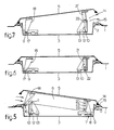
- the drawings show an embodiment of a ventilating hatch for a vehicle, such as a truck, of which the fixed roof 1 is provided with an opening 2.
- the ventilating hatch has a stationary frame 3, which is mounted in the roof opening 2 of the vehicle.
- the stationary frame 3 comprises a passage 4.
- the ventilating hatch is further provided with a panel 5, which closes the passage 4 in the stationary frame 3 in its closed position. From this closed position (fig. 2) the panel 5 may selectively be set in a rearwardly and upwardly inclined position (fig. 3), in a forwardly and upwardly inclined position (fig. 5) or in a position (fig. 4), in which the panel is substantially parallel to the stationary frame 3 and is spaced above the passage 4.
- the front side of the vehicle and consequently the front side of the ventilating hatch is at the left side of the drawings.
- the ventilating hatch is principally constructed of three main parts, that is the stationary frame 3, the panel 5 and an intermediate frame 6 provided between both former parts.
- This intermediate frame 6 is pivotally connected to the stationary frame 3 at the rear side of the ventilating hatch, which is indicated by reference numeral 7, and the panel 5 is pivotally connected to the intermediate frame 6 at the front side of the ventilating hatch at 16.
- the intermediate frame 6 has two of such plates, one at each longitudinal side of the ventilating hatch, the plates being rigidly connected to each other by transverse connections.
- the elements of the plate and the elements of panel 5 and the stationary frame 3 cooperating therewith, which will be described in detail hereinafter are normally provided at both longitudinal sides of the ventilating hatch.
- the pivot joint 7 between the intermediate frame 6 and the stationary frame 3 consists of a pivot pin 8 provided near the rear side of the intermediate frame 6 and engaging in a slot 9 formed in the stationary frame 3 and inclining forwardly and upwardly from the rear side of the ventilating hatch.
- a pin slot assembly 10 At the front side of the ventilating hatch the stationary frame 3 and the intermediate frame 6 are guided with respect to each other by means of a pin slot assembly 10.
- a guide pin 11 of this assembly 10 is provided near the front side of the intermediate frame 6, and a guide slot 12 is formed in a support 13 of the stationary frame 3.
- the guide slot 12 has a configuration of a segment of a circle.
- the circular guide slot 12 in the support 13 of the stationary frame 3 does not extend concentrically about the pivot joint 7 between the intermediate frame 6 and the stationary frame 3, so that the pivot pin 8 moves forwardly and upwardly (see fig. 5) from its rear position in the slot 9 (see e.g. fig. 2) when the intermediate frame is tilted from its lower position.
- the inclination of the slot 9 and the path of the guide slot 12 are chosen such, that when the above mentioned tilting movement is effected the imaginary pivot axis of the panel 5 substantially coincide with a seal 14 at the rear side of the panel.
- the pivot joint 16 between the panel 5 and the intermediate frame 6 is formed in a similar way by a pivot pin 17 carried by a support 18 at the lower side of the panel 5 and engaging in a slot 19 formed near the front side of the intermediate frame 6.
- This slot 19 extends rearwardly and upwardly inclined from the front side of the ventilating hatch.
- the intermediate frame 6 and the panel 5 are guided with respect to each other by means of a pin-slot assembly 20.
- a support 21 mounted at the lower side of the panel carries a guide pin 22 of the pin-slot assembly 20, and a guide slot 23 thereof is formed in the intermediate frame 6.
- the tilting movement of the panel 5 with respect to the intermediate frame 6 takes place in a similar way as the tilting movement of the intermediate frame 6 with respect to the stationary frame 3.
- the seal 14 at the front side of the panel 5 will be in engagement with the cooperating sealing face 15 in each rearwardly and upwardly inclined position, so that it is prevented that air or water will enter the interior of the vehicle at the front side of the panel 5 when the vehicle is driving.
- Fig. 1 further shows in a schematic way an adjusting mechanism 24 for adjusting the intermediate frame 6 with respect to the stationary frame 3, and an adjusting mechanism 25 with which the panel 5 is adjustable with respect to the intermediate frame 6.
- the adjusting mechanism 24 is manually operated and permits only a locking operation in both extreme positions.
- a lever arrangement 28 is rotated by means of a handle 26 through a gear transmission 27, thereby causing the intermediate frame 6 to tilt about a pivot pin.
- the lever arrangement engages the intermediate frame 6 at a point 29.
- the adjusting mechanism 25 comprises a corresponding lever arrangement 30, which is, however, rotated by an electric motor 31 provided on the intermediate frame 6.
- the lever arrangement 30 is connected to the panel 5 at a point 32.
- the ventilating hatch according to the invention is constructed such, that it is possible to convert the multiple adjustable ventilating hatch, shown in the fig. 1-5, into a singular adjustable ventilating hatch as shown in fig. 6 and 7. In this fashion the panel 5 can only be tilted between the closed position (fig. 6) and a rearwardly and upwardly inclined position (fig. 7).
- the intermediate frame 6 is removably mounted in the ventilating hatch.
- the conversion has to be effected it is only necessary to remove the intermediate frame 6, to turn the stationary frame 3 180° about a vertical axis and to mount the panel 5 to the stationary frame 3.
- the pivot joints 7 and 16 between the stationary frame 3 and the intermediate frame 6, and between the panel 5 and the intermediate frame 6, respectively are constructed in a similar way. Consequently the pivot pin 17 of the panel 5 is permitted to be fitted in the slot 9 of the stationary frame 3.
- pin-slot assemblies 10 and 20 are also constructed in a similar way, so that the guide pin 22 of the panel is able to cooperate with the guide slot 12 in the support 13 of the stationary frame 3.
- both pivot joints 7 and 16 and both pin-slot assemblies 10 and 20 are arranged symmetrically with respect to a vertical transverse plane.
- the adjustment of the panel 5 takes place by means of the adjusting mechanism 24, of which the lever arrangement 28 engages the panel 5 at the pivot point 32.
- the ventilating hatch shown in fig. 1-5 is also constructed as a removable emergency hatch for providing an emergency exit in cases of emergency.
- a sectional strip 33 is provided along the front transverse side of the stationary frame 3, the sectional strip 33 being able to cooperate with a sectional strip 34 mounted on the fixed roof 1.
- These sectional strips 33 and 34 together form a fastening means between the stationary frame and the fixed roof 1 at the respective transverse side of the ventilating hatch 1, and in case of emergency these sectional strips 33 and 34 together form a pivot joint, so that, after loosening a removable joint 35 between the stationary frame 3 and fixed roof 1 at the opposite transverse side, the complete ventilating hatch is permitted to be tilted outwardly. In this way the opening 2 in the fixed roof 1 provides an emergency exit which is as large as possible.
Landscapes
- Engineering & Computer Science (AREA)
- Mechanical Engineering (AREA)
- Air-Conditioning For Vehicles (AREA)
Applications Claiming Priority (2)
| Application Number | Priority Date | Filing Date | Title |
|---|---|---|---|
| NL8601530 | 1986-06-13 | ||
| NL8601530A NL8601530A (nl) | 1986-06-13 | 1986-06-13 | Ventilatieluik. |
Publications (2)
| Publication Number | Publication Date |
|---|---|
| EP0249268A1 true EP0249268A1 (de) | 1987-12-16 |
| EP0249268B1 EP0249268B1 (de) | 1990-03-21 |
Family
ID=19848164
Family Applications (1)
| Application Number | Title | Priority Date | Filing Date |
|---|---|---|---|
| EP19870200968 Expired EP0249268B1 (de) | 1986-06-13 | 1987-05-21 | Dachbelüftungsfenster |
Country Status (3)
| Country | Link |
|---|---|
| EP (1) | EP0249268B1 (de) |
| DE (1) | DE3761961D1 (de) |
| NL (1) | NL8601530A (de) |
Cited By (8)
| Publication number | Priority date | Publication date | Assignee | Title |
|---|---|---|---|---|
| EP0347958A1 (de) * | 1988-06-20 | 1989-12-27 | Vermeulen-Hollandia Octrooien II B.V. | Lüftungs- und Notausstiegsluke |
| DE3835018A1 (de) * | 1988-10-14 | 1990-04-19 | Webasto Ag Fahrzeugtechnik | Fahrzeugdach |
| GB2232643A (en) * | 1989-03-14 | 1990-12-19 | Rockwell Golde Gmbh | Mounting unit for motor vehicle sliding roof |
| WO1997039906A1 (en) * | 1996-04-23 | 1997-10-30 | Boomsma Produktie B.V. | Lever mechanism for controlling a roof hatch |
| EP0826538A1 (de) * | 1996-08-30 | 1998-03-04 | WEBASTO THERMOSYSTEME GmbH | Fahrzeugdach |
| EP0841233A3 (de) * | 1996-11-07 | 1999-12-08 | ABB Daimler-Benz Transportation (Technology) GmbH | Schienenfahrzeug |
| EP0976595A1 (de) * | 1998-07-31 | 2000-02-02 | MAN Nutzfahrzeuge Aktiengesellschaft | Bedienhebel für einen Dachlukendeckel eines Lastkraftwagens |
| EP1378386A1 (de) * | 2002-07-06 | 2004-01-07 | DaimlerChrysler AG | Fahrerhaus mit Dachluke |
Citations (5)
| Publication number | Priority date | Publication date | Assignee | Title |
|---|---|---|---|---|
| GB927923A (en) * | 1959-12-29 | 1963-06-06 | Gerrit Frederik Boomsma | Improvements in and relating to pivoted ventilators |
| DE1952126A1 (de) * | 1968-10-18 | 1970-04-30 | Robertshaw Michael Firth | Dach-Lueftgeraet |
| DE2260913A1 (de) * | 1972-12-13 | 1974-06-20 | Grescha Ges Grefe & Scharf | Vorrichtung zum be- und entlueften von gebaeuderaeumen |
| EP0002919A1 (de) * | 1977-12-20 | 1979-07-11 | Williaam Cox Limited | Dachluke für Wohnwagen |
| US4522115A (en) * | 1983-07-29 | 1985-06-11 | Ventilator Associates | Ventilator for vehicle |
-
1986
- 1986-06-13 NL NL8601530A patent/NL8601530A/nl not_active Application Discontinuation
-
1987
- 1987-05-21 DE DE8787200968T patent/DE3761961D1/de not_active Expired - Fee Related
- 1987-05-21 EP EP19870200968 patent/EP0249268B1/de not_active Expired
Patent Citations (5)
| Publication number | Priority date | Publication date | Assignee | Title |
|---|---|---|---|---|
| GB927923A (en) * | 1959-12-29 | 1963-06-06 | Gerrit Frederik Boomsma | Improvements in and relating to pivoted ventilators |
| DE1952126A1 (de) * | 1968-10-18 | 1970-04-30 | Robertshaw Michael Firth | Dach-Lueftgeraet |
| DE2260913A1 (de) * | 1972-12-13 | 1974-06-20 | Grescha Ges Grefe & Scharf | Vorrichtung zum be- und entlueften von gebaeuderaeumen |
| EP0002919A1 (de) * | 1977-12-20 | 1979-07-11 | Williaam Cox Limited | Dachluke für Wohnwagen |
| US4522115A (en) * | 1983-07-29 | 1985-06-11 | Ventilator Associates | Ventilator for vehicle |
Cited By (10)
| Publication number | Priority date | Publication date | Assignee | Title |
|---|---|---|---|---|
| EP0347958A1 (de) * | 1988-06-20 | 1989-12-27 | Vermeulen-Hollandia Octrooien II B.V. | Lüftungs- und Notausstiegsluke |
| DE3835018A1 (de) * | 1988-10-14 | 1990-04-19 | Webasto Ag Fahrzeugtechnik | Fahrzeugdach |
| GB2232643A (en) * | 1989-03-14 | 1990-12-19 | Rockwell Golde Gmbh | Mounting unit for motor vehicle sliding roof |
| US5048889A (en) * | 1989-03-14 | 1991-09-17 | Rockwell-Golde G.M.B.H. | Mounting unit for motor vehicle sliding roofs |
| GB2232643B (en) * | 1989-03-14 | 1992-11-04 | Rockwell Golde Gmbh | Mounting vehicle sliding roof assembly. |
| WO1997039906A1 (en) * | 1996-04-23 | 1997-10-30 | Boomsma Produktie B.V. | Lever mechanism for controlling a roof hatch |
| EP0826538A1 (de) * | 1996-08-30 | 1998-03-04 | WEBASTO THERMOSYSTEME GmbH | Fahrzeugdach |
| EP0841233A3 (de) * | 1996-11-07 | 1999-12-08 | ABB Daimler-Benz Transportation (Technology) GmbH | Schienenfahrzeug |
| EP0976595A1 (de) * | 1998-07-31 | 2000-02-02 | MAN Nutzfahrzeuge Aktiengesellschaft | Bedienhebel für einen Dachlukendeckel eines Lastkraftwagens |
| EP1378386A1 (de) * | 2002-07-06 | 2004-01-07 | DaimlerChrysler AG | Fahrerhaus mit Dachluke |
Also Published As
| Publication number | Publication date |
|---|---|
| EP0249268B1 (de) | 1990-03-21 |
| NL8601530A (nl) | 1988-01-04 |
| DE3761961D1 (de) | 1990-04-26 |
Similar Documents
| Publication | Publication Date | Title |
|---|---|---|
| US4081926A (en) | Sunroof | |
| US5054377A (en) | Vehicle ventilation | |
| JP2680911B2 (ja) | スライディングルーフ | |
| US4067605A (en) | Detachable sun roof panel for automobiles | |
| US5284378A (en) | Self-storing convertible top latch system | |
| EP0134042A2 (de) | Hebeschiebedach | |
| EP0249268B1 (de) | Dachbelüftungsfenster | |
| GB2078295A (en) | Sliding roof | |
| US4185868A (en) | Electrically operated hatch roofs | |
| JP2865366B2 (ja) | 車両の換気ルーフ | |
| US3970343A (en) | Sunroof structure | |
| EP1009644B1 (de) | Verfahren zum öffnen und schliessen einer öffnungsfähigen dachherstellung für ein fahrzeug mit einer öffnung im festen dach, sowie solche öffnungsfähige dachherstellung | |
| JP2834269B2 (ja) | エアデフレクタを備えた車両ルーフ | |
| EP0468587B1 (de) | Kraftfahrzeug-Hebeschiebedach | |
| EP0325380B1 (de) | Vorrichtung zum Öffnen und Schliessen des Schiebedachs eines Fahrzeuges | |
| GB2056380A (en) | Vehicle sunroof structure | |
| US4231608A (en) | Sunroof structure | |
| JPH02246825A (ja) | 車両のスライドルーフおよびスライドチルトルーフ | |
| US4193628A (en) | Bayonet structure for detachable sunroof | |
| US5048889A (en) | Mounting unit for motor vehicle sliding roofs | |
| US3888165A (en) | Ventilator for a motor vehicle roof | |
| US6959961B2 (en) | Louver vehicle roof | |
| JPH05246246A (ja) | 車両用スライドチルトルーフ | |
| US4227739A (en) | Sunroof opening and locking device | |
| EP0388905B1 (de) | Lüftungslenke für die Fahrerkabine eines Lastkraftwagens |
Legal Events
| Date | Code | Title | Description |
|---|---|---|---|
| PUAI | Public reference made under article 153(3) epc to a published international application that has entered the european phase |
Free format text: ORIGINAL CODE: 0009012 |
|
| AK | Designated contracting states |
Kind code of ref document: A1 Designated state(s): DE FR GB IT NL SE |
|
| 17P | Request for examination filed |
Effective date: 19880615 |
|
| 17Q | First examination report despatched |
Effective date: 19890214 |
|
| GRAA | (expected) grant |
Free format text: ORIGINAL CODE: 0009210 |
|
| AK | Designated contracting states |
Kind code of ref document: B1 Designated state(s): DE FR GB IT NL SE |
|
| REF | Corresponds to: |
Ref document number: 3761961 Country of ref document: DE Date of ref document: 19900426 |
|
| ET | Fr: translation filed | ||
| ITF | It: translation for a ep patent filed | ||
| PLBE | No opposition filed within time limit |
Free format text: ORIGINAL CODE: 0009261 |
|
| STAA | Information on the status of an ep patent application or granted ep patent |
Free format text: STATUS: NO OPPOSITION FILED WITHIN TIME LIMIT |
|
| 26N | No opposition filed | ||
| ITTA | It: last paid annual fee | ||
| EAL | Se: european patent in force in sweden |
Ref document number: 87200968.3 |
|
| REG | Reference to a national code |
Ref country code: GB Ref legal event code: IF02 |
|
| NLS | Nl: assignments of ep-patents |
Owner name: WEBASTOHOLLANDIA HOLDING B.V. |
|
| NLT1 | Nl: modifications of names registered in virtue of documents presented to the patent office pursuant to art. 16 a, paragraph 1 |
Owner name: WEBASTOHOLLANDIA OCTROOIEN B.V. Owner name: WEBASTO PRODUCT INTERNATIONAL NL B.V. |
|
| PGFP | Annual fee paid to national office [announced via postgrant information from national office to epo] |
Ref country code: FR Payment date: 20050509 Year of fee payment: 19 |
|
| PGFP | Annual fee paid to national office [announced via postgrant information from national office to epo] |
Ref country code: SE Payment date: 20050517 Year of fee payment: 19 |
|
| PGFP | Annual fee paid to national office [announced via postgrant information from national office to epo] |
Ref country code: GB Payment date: 20050518 Year of fee payment: 19 |
|
| PGFP | Annual fee paid to national office [announced via postgrant information from national office to epo] |
Ref country code: NL Payment date: 20050531 Year of fee payment: 19 Ref country code: DE Payment date: 20050531 Year of fee payment: 19 |
|
| PG25 | Lapsed in a contracting state [announced via postgrant information from national office to epo] |
Ref country code: GB Free format text: LAPSE BECAUSE OF NON-PAYMENT OF DUE FEES Effective date: 20060521 |
|
| PG25 | Lapsed in a contracting state [announced via postgrant information from national office to epo] |
Ref country code: SE Free format text: LAPSE BECAUSE OF NON-PAYMENT OF DUE FEES Effective date: 20060522 |
|
| PGFP | Annual fee paid to national office [announced via postgrant information from national office to epo] |
Ref country code: IT Payment date: 20060531 Year of fee payment: 20 |
|
| PG25 | Lapsed in a contracting state [announced via postgrant information from national office to epo] |
Ref country code: NL Free format text: LAPSE BECAUSE OF NON-PAYMENT OF DUE FEES Effective date: 20061201 Ref country code: DE Free format text: LAPSE BECAUSE OF NON-PAYMENT OF DUE FEES Effective date: 20061201 |
|
| EUG | Se: european patent has lapsed | ||
| GBPC | Gb: european patent ceased through non-payment of renewal fee |
Effective date: 20060521 |
|
| NLV4 | Nl: lapsed or anulled due to non-payment of the annual fee |
Effective date: 20061201 |
|
| REG | Reference to a national code |
Ref country code: FR Ref legal event code: ST Effective date: 20070131 |
|
| PG25 | Lapsed in a contracting state [announced via postgrant information from national office to epo] |
Ref country code: FR Free format text: LAPSE BECAUSE OF NON-PAYMENT OF DUE FEES Effective date: 20060531 |